EP0634608A2 - Doppelring-Gasbrenner - Google Patents
Doppelring-Gasbrenner Download PDFInfo
- Publication number
- EP0634608A2 EP0634608A2 EP94111038A EP94111038A EP0634608A2 EP 0634608 A2 EP0634608 A2 EP 0634608A2 EP 94111038 A EP94111038 A EP 94111038A EP 94111038 A EP94111038 A EP 94111038A EP 0634608 A2 EP0634608 A2 EP 0634608A2
- Authority
- EP
- European Patent Office
- Prior art keywords
- burner
- cup
- seat
- disc
- flame divider
- Prior art date
- Legal status (The legal status is an assumption and is not a legal conclusion. Google has not performed a legal analysis and makes no representation as to the accuracy of the status listed.)
- Withdrawn
Links
- 238000010411 cooking Methods 0.000 claims abstract description 21
- 239000000203 mixture Substances 0.000 claims description 7
- 230000000295 complement effect Effects 0.000 claims description 2
- 230000037431 insertion Effects 0.000 claims 2
- 238000003780 insertion Methods 0.000 claims 2
- 239000002184 metal Substances 0.000 description 5
- 238000000605 extraction Methods 0.000 description 2
- 235000001674 Agaricus brunnescens Nutrition 0.000 description 1
- 229910000831 Steel Inorganic materials 0.000 description 1
- 238000004140 cleaning Methods 0.000 description 1
- 238000002485 combustion reaction Methods 0.000 description 1
- 238000010276 construction Methods 0.000 description 1
- 238000004519 manufacturing process Methods 0.000 description 1
- 239000010959 steel Substances 0.000 description 1
Images


Classifications
-
- F—MECHANICAL ENGINEERING; LIGHTING; HEATING; WEAPONS; BLASTING
- F23—COMBUSTION APPARATUS; COMBUSTION PROCESSES
- F23D—BURNERS
- F23D14/00—Burners for combustion of a gas, e.g. of a gas stored under pressure as a liquid
- F23D14/46—Details, e.g. noise reduction means
- F23D14/72—Safety devices, e.g. operative in case of failure of gas supply
- F23D14/725—Protection against flame failure by using flame detection devices
-
- F—MECHANICAL ENGINEERING; LIGHTING; HEATING; WEAPONS; BLASTING
- F23—COMBUSTION APPARATUS; COMBUSTION PROCESSES
- F23D—BURNERS
- F23D14/00—Burners for combustion of a gas, e.g. of a gas stored under pressure as a liquid
- F23D14/02—Premix gas burners, i.e. in which gaseous fuel is mixed with combustion air upstream of the combustion zone
- F23D14/04—Premix gas burners, i.e. in which gaseous fuel is mixed with combustion air upstream of the combustion zone induction type, e.g. Bunsen burner
- F23D14/06—Premix gas burners, i.e. in which gaseous fuel is mixed with combustion air upstream of the combustion zone induction type, e.g. Bunsen burner with radial outlets at the burner head
-
- F—MECHANICAL ENGINEERING; LIGHTING; HEATING; WEAPONS; BLASTING
- F23—COMBUSTION APPARATUS; COMBUSTION PROCESSES
- F23D—BURNERS
- F23D2207/00—Ignition devices associated with burner
-
- F—MECHANICAL ENGINEERING; LIGHTING; HEATING; WEAPONS; BLASTING
- F23—COMBUSTION APPARATUS; COMBUSTION PROCESSES
- F23D—BURNERS
- F23D2900/00—Special features of, or arrangements for burners using fluid fuels or solid fuels suspended in a carrier gas
- F23D2900/14—Special features of gas burners
- F23D2900/14062—Special features of gas burners for cooking ranges having multiple flame rings
Definitions
- This invention relates to a double ring gas burner particularly for built-in cooking hobs.
- Double ring gas burners comprising a cup of overall cylindrical shape, a burner body positioned on said cup and partly housed therein, and an annular flame divider provided in its outer edge and inner edge with two series of apertures through which a combustible gas-air mixture is delivered.
- the gas is fed by a nozzle positioned on the base of the cup, the air (primary air) being drawn in through ports situated above the cooking hob and kept separated from the secondary air by a horizontal baffle which prevents the dirt inevitably formed in the hob from entering the cup.
- both the passages for the primary air and the passages for the secondary air which feeds the inner ring of the burner require for this purpose to project a certain extent above the hob, with possible problems of a technical nature in the positioning of the pan support grid and the application of a closure cover to said hob, in addition to possible detriment to apperance.
- An object of the invention is to provide a double ring gas burner, particularly for built-in cooking hobs, which has the advantages of known double ring burners of pipe and cup type, while at the same time eliminating their respective drawbacks.
- a more particular object of the invention is to provide a double ring gas burner which allows easy extraction of the gas delivery nozzle from above without having to open up the hob.
- a further object of the invention is to provide a double ring gas burner which is practically insensitive to the presence of other burners in operation on the same hob.
- a further object of the invention is to provide a double ring gas burner in which the entry of dirt into the burner cup is practically eliminated.
- a further object of the invention is to provide a double ring gas burner comprising an ignition spark plug and safety thermocouple, both withdrawable from above.
- thermocouple and spark plug do not represent an obstacle to the usual cleaning of the cooking hob.
- a further object of the invention is to provide a double ring gas burner with a flame divider element which combines the merits of high flame stability with the merits of low production cost.
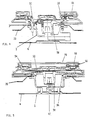
- the double ring gas burner according to the invention comprises an injector support cup 2 applied to the metal plate 4 which lowerly bounds a traditional cooking hob, indicated overall by 6.
- the cup 2 is provided on its base with a gas delivery nozzle 12 and is also provided at its open upper edge with a flange 14 and a overlying circumferential groove 16 for housing a steel ring 18 the purpose of which is to removably secure the cup to the upper metal plate 20 of the cooking hob 6.
- the side wall of the cup 2 comprises a plurality of apertures 24 through which the primary air stream is drawn in from the outside of the cup, and also comprises two parallel enlarged portions 26, 28 situated in substantially diametrical position and provided for receiving a thermocouple 10 and a burner ignition spark plug 30.
- the apertures 24 are below the upper metal plate.
- a plurality of notches 32 complementary to appendices 34 projecting from the lower surface of the burner body 36, which is positionable on said cup 2 and is secured in its angular position by the engagement between said appendices and said notches.
- the burner body 36 is of traditional mushroom shape, with an axial duct 38 and an overlying rim 40.
- the axial duct 38 is of essentially cylindrical shape and lowerly comprises a plurality of lateral apertures 42 for entry of the primary air which is to mix with the gas leaving the nozzle 12.
- the axial duct 38 can be fitted with a sleeve 44 provided with lateral apertures 46 which, according to the angular position of the sleeve, face its apertures 42 to a greater or lesser extent, to hence regulate the primary air flow.
- the angular position of the sleeve 44 relative to the axial duct 38 can be stabilized for example by a screw passing through a slot 48 provided in the sleeve 44 and engaging in the burner body 36.
- the burner body 36 also comprises a disc-shaped portion 50 of which the circumferential edge, step-shaped, rests on the edge of the cup 2 and is provided with appendices 34. This disc-shaped portion 50 completely closes the cup 2 to prevent dirt entering it.
- the rim 40 of the burner body 36 comprises radial channels 52 connecting the axial duct 38 to an annular chamber 54 which, as will be more apparent hereinafter, houses a flame divider element 56.
- the radial channels 52 of which four are provided in the illustrated example, have a certain downward inclination starting from the centre of the burner and hence of the cooking hob.
- thermocouple 10 and spark plug 30 are aligned coaxially with the seats provided in the two enlarged portions 26, 28 of the side wall of the cup 2, to allow passage of the thermocouple 10 and spark plug 30, which are hence contained within the overall outline of the burner and can be easily inserted from above during burner assembly and replaced when necessary.
- thermocouple seat is internally threaded and provided on its base with a connector to provide electrical contact with the lower terminal of the thermocouple 10 when screwed into its seat.
- the flame divider element 56 consists essentially of two cylindrical coaxial bands 58, 60 joined together by an annular web 62, to give the flame divider element an overall "H" configuration in cross-section. Both the coaxial bands 58, 60 are provided in both edges with a plurality of equidistant recesses 64, forming the two inner and outer main rings and inner and outer pilot rings.
- thermocouple The recesses forming the main ring and facing the thermocouple are inclined downwards to be able to use a thermocouple of standard type and hence maintain a small overall height of the assembly.
- annular web 62 connecting together the two cylindrical bands 58, 60 there are provided a plurality of apertures 66 which because of the particular position (obligatory) of the flame divider element 56 relative to the burner body 36 do not face the outlets by which the radial channels 52 open into the annular chamber 54.
- a short radial duct 68 the purpose of which, as described hereinafter, is to propagate the flame from the inner ring to the outer ring of the burner.
- a traditional annular cover 70 can be applied to the flame divider element.
- the double ring burner according to the invention consists substantially of two assembled parts.
- the first comprises the cup 2 fixed in the described manner to the cooking hob 6, and the second comprises the burner body 36 with its regulator sleeve 44, the flame divider element 56 housed in the annular cavity 54 of the body 36 and the cover 70 applied to the flame divider element.
- This second burner part is removably supported on the egde of the cup 2 in an obligatory angular position, and can be easily removed when necessary.
- the double ring gas burner of the invention operates as follows: primary air is fed to the burner by passing from the interspace between the two metal plates 4 and 20 of the cooking hob 6 housing it, and through the apertures 24 provided in the side wall of the cup 2 until it grazes the nozzle 12 provided on the base of this latter, to be then entrained by the gas to form the combustible mixture.
- the spark plug 30 When the spark plug 30 is activated, the spark ignites the mixture emerging from the pilot recesses 64 of the inner ring 60 which lie in front of said spark plug 30.
- the flame which forms propagates progressively to all the other pilot and main recesses of the inner ring and also, by virtue of the radial duct 68 provided in the flame divider element 56, to the main and pilot recesses of the outer ring.
- the flames striking the thermocouple 10 activate it to cause the safety cock to remain open.
- the secondary air for the combustion of the gas-primary air mixture in the inner ring passes below the rim 40 and between this and the upper plate 20 of the cooking hob to upperly graze the disc-shaped element 50.
- the double ring gas burner of the invention is advantageous compared with traditional burners, and in particular:
Landscapes
- Engineering & Computer Science (AREA)
- Chemical & Material Sciences (AREA)
- Combustion & Propulsion (AREA)
- Mechanical Engineering (AREA)
- General Engineering & Computer Science (AREA)
- Gas Burners (AREA)
Applications Claiming Priority (2)
| Application Number | Priority Date | Filing Date | Title |
|---|---|---|---|
| IT93VE000018A IT1268490B1 (it) | 1993-07-16 | 1993-07-16 | Bruciatore a gas a doppia corona particolarmente per piani di cottura ad incasso |
| ITVE930018 | 1993-07-16 |
Publications (2)
| Publication Number | Publication Date |
|---|---|
| EP0634608A2 true EP0634608A2 (de) | 1995-01-18 |
| EP0634608A3 EP0634608A3 (de) | 1995-06-21 |
Family
ID=11423933
Family Applications (1)
| Application Number | Title | Priority Date | Filing Date |
|---|---|---|---|
| EP94111038A Withdrawn EP0634608A3 (de) | 1993-07-16 | 1994-07-15 | Doppelring-Gasbrenner. |
Country Status (2)
| Country | Link |
|---|---|
| EP (1) | EP0634608A3 (de) |
| IT (1) | IT1268490B1 (de) |
Cited By (23)
| Publication number | Priority date | Publication date | Assignee | Title |
|---|---|---|---|---|
| WO1998012475A1 (fr) * | 1996-09-19 | 1998-03-26 | Sourdillon | Bruleur a gaz, notamment pour appareil culinaire, et procedes pour son montage et son utilisation |
| FR2770620A1 (fr) | 1997-11-04 | 1999-05-07 | Sourdillon Sa | Bruleur a gaz pour cuisiniere ou plan de cuisson |
| ES2147076A1 (es) * | 1997-03-14 | 2000-08-16 | Sourdillon Sa | Quemador de gas para cocinas, perfeccionado. |
| EP1120603A2 (de) * | 2000-01-28 | 2001-08-01 | Sourdillon | Gasbrenner mit mehreren Flamenringen |
| WO2002002991A1 (en) * | 2000-07-06 | 2002-01-10 | Sabaf S.P.A. | Burner with internal separator |
| US6589046B2 (en) * | 2001-08-21 | 2003-07-08 | Uwe Harneit | Gas burner for outdoor cooking |
| WO2004113792A1 (en) * | 2003-06-23 | 2004-12-29 | Sami Srl | Triple crown gas burner |
| WO2006046922A1 (en) * | 2004-10-28 | 2006-05-04 | Aktiebolaget Electrolux | Improved cooking gas burner |
| WO2007007298A2 (en) * | 2005-07-14 | 2007-01-18 | Enkay Bek Metal Enjeksiyon Sanayi Ticaret Limited Sirkei | A gas burner |
| CN1920383B (zh) * | 2006-09-18 | 2010-09-29 | 谭六明 | 上进风式深内旋燃烧器 |
| US7878800B2 (en) * | 2002-11-12 | 2011-02-01 | Sabaf S.P.A. | Gas burner with separate feeding of the flame crowns |
| CN102889620A (zh) * | 2011-07-21 | 2013-01-23 | 林内株式会社 | 燃气炉具 |
| CN102901100A (zh) * | 2012-09-28 | 2013-01-30 | 杭州老板电器股份有限公司 | 一种环保洁净燃烧器 |
| WO2013064657A1 (en) * | 2011-11-04 | 2013-05-10 | Somipress - Societa' Metalli Iniettati S.P.A. | A gas burner with inward-facing flame. |
| US8967997B2 (en) | 2012-02-13 | 2015-03-03 | Factory Mutual Insurance Company | System and components for evaluating the performance of fire safety protection devices |
| US8973569B2 (en) | 2009-02-18 | 2015-03-10 | Electrolux Home Products, Inc. | Gas burner |
| US9694223B2 (en) | 2012-02-13 | 2017-07-04 | Factory Mutual Insurance Company | System and components for evaluating the performance of fire safety protection devices |
| CN109000236A (zh) * | 2018-09-04 | 2018-12-14 | 佛山市顺德区美的洗涤电器制造有限公司 | 燃烧器及燃气灶具 |
| CN109000248A (zh) * | 2018-09-04 | 2018-12-14 | 佛山市顺德区美的洗涤电器制造有限公司 | 底杯及燃烧器及燃气灶具 |
| ES2697724A1 (es) * | 2017-07-26 | 2019-01-28 | Copreci S Coop | Conjunto de quemador de gas para un aparato de cocción de gas, y aparato de cocción de gas que incorpora dicho conjunto de quemador de gas |
| CN109959009A (zh) * | 2017-12-26 | 2019-07-02 | 宁波方太厨具有限公司 | 一种灶具燃烧器的火盖结构以及应用有该火盖结构的燃烧器 |
| CN109959008A (zh) * | 2017-12-26 | 2019-07-02 | 宁波方太厨具有限公司 | 一种用于燃气灶的燃烧器火盖 |
| CN110864295A (zh) * | 2019-10-31 | 2020-03-06 | 宁波方太厨具有限公司 | 外环火盖、应用该火盖的燃烧器及应用该燃烧器的燃气灶 |
Citations (3)
| Publication number | Priority date | Publication date | Assignee | Title |
|---|---|---|---|---|
| GB715036A (en) * | 1950-07-05 | 1954-09-08 | Willy Homann | Improvements in or relating to cooking positions for gas ranges or cookers |
| EP0125965A1 (de) * | 1983-04-29 | 1984-11-21 | Gaz De France | Brenner für gasförmigen Brennstoff mit eingebautem Zünd- und Sicherheitssystem |
| EP0534301A2 (de) * | 1991-09-26 | 1993-03-31 | MERLONI ELETTRODOMESTICI S.p.A. | Gasbrenner zum Kochen von Nahrungsmitteln |
-
1993
- 1993-07-16 IT IT93VE000018A patent/IT1268490B1/it active IP Right Grant
-
1994
- 1994-07-15 EP EP94111038A patent/EP0634608A3/de not_active Withdrawn
Patent Citations (3)
| Publication number | Priority date | Publication date | Assignee | Title |
|---|---|---|---|---|
| GB715036A (en) * | 1950-07-05 | 1954-09-08 | Willy Homann | Improvements in or relating to cooking positions for gas ranges or cookers |
| EP0125965A1 (de) * | 1983-04-29 | 1984-11-21 | Gaz De France | Brenner für gasförmigen Brennstoff mit eingebautem Zünd- und Sicherheitssystem |
| EP0534301A2 (de) * | 1991-09-26 | 1993-03-31 | MERLONI ELETTRODOMESTICI S.p.A. | Gasbrenner zum Kochen von Nahrungsmitteln |
Cited By (41)
| Publication number | Priority date | Publication date | Assignee | Title |
|---|---|---|---|---|
| WO1998012475A1 (fr) * | 1996-09-19 | 1998-03-26 | Sourdillon | Bruleur a gaz, notamment pour appareil culinaire, et procedes pour son montage et son utilisation |
| ES2147076A1 (es) * | 1997-03-14 | 2000-08-16 | Sourdillon Sa | Quemador de gas para cocinas, perfeccionado. |
| FR2770620A1 (fr) | 1997-11-04 | 1999-05-07 | Sourdillon Sa | Bruleur a gaz pour cuisiniere ou plan de cuisson |
| EP1120603A2 (de) * | 2000-01-28 | 2001-08-01 | Sourdillon | Gasbrenner mit mehreren Flamenringen |
| FR2804496A1 (fr) * | 2000-01-28 | 2001-08-03 | Sourdillon Sa | Bruleur a gaz a multiples couronnes de flammes |
| EP1120603A3 (de) * | 2000-01-28 | 2001-08-16 | Sourdillon | Gasbrenner mit mehreren Flamenringen |
| US6325619B2 (en) | 2000-01-28 | 2001-12-04 | Sourdillon | Gas burner with multiple gas rings |
| US7001176B2 (en) | 2000-07-06 | 2006-02-21 | Sabaf S.P.A. | Burner with internal separator |
| KR100890089B1 (ko) * | 2000-07-06 | 2009-03-24 | 사바프 에스. 피. 에이. | 내부 분리기가 있는 버너 |
| WO2002002991A1 (en) * | 2000-07-06 | 2002-01-10 | Sabaf S.P.A. | Burner with internal separator |
| US6589046B2 (en) * | 2001-08-21 | 2003-07-08 | Uwe Harneit | Gas burner for outdoor cooking |
| US7878800B2 (en) * | 2002-11-12 | 2011-02-01 | Sabaf S.P.A. | Gas burner with separate feeding of the flame crowns |
| WO2004113792A1 (en) * | 2003-06-23 | 2004-12-29 | Sami Srl | Triple crown gas burner |
| WO2006046922A1 (en) * | 2004-10-28 | 2006-05-04 | Aktiebolaget Electrolux | Improved cooking gas burner |
| US8887710B2 (en) | 2004-10-28 | 2014-11-18 | Aktiebolaget Electrolux | Cooking gas burner |
| CN102563714B (zh) * | 2004-10-28 | 2014-11-12 | 电气联合股份有限公司 | 改进的厨用燃气灶 |
| WO2007007298A3 (en) * | 2005-07-14 | 2007-03-29 | Enkay Bek Metal Enjeksiyon San | A gas burner |
| WO2007007298A2 (en) * | 2005-07-14 | 2007-01-18 | Enkay Bek Metal Enjeksiyon Sanayi Ticaret Limited Sirkei | A gas burner |
| CN1920383B (zh) * | 2006-09-18 | 2010-09-29 | 谭六明 | 上进风式深内旋燃烧器 |
| US8973569B2 (en) | 2009-02-18 | 2015-03-10 | Electrolux Home Products, Inc. | Gas burner |
| CN102889620A (zh) * | 2011-07-21 | 2013-01-23 | 林内株式会社 | 燃气炉具 |
| CN102889620B (zh) * | 2011-07-21 | 2016-08-10 | 林内株式会社 | 燃气炉具 |
| CN103906974A (zh) * | 2011-11-04 | 2014-07-02 | Somipress注射金属协会有限公司 | 具有向内火焰的燃气燃烧器 |
| WO2013064657A1 (en) * | 2011-11-04 | 2013-05-10 | Somipress - Societa' Metalli Iniettati S.P.A. | A gas burner with inward-facing flame. |
| US9625159B2 (en) | 2011-11-04 | 2017-04-18 | Somipress—Societa'metalli Iniettati S.P.A. | Gas burner with inward facing flame |
| WO2013122660A3 (en) * | 2012-02-13 | 2016-05-12 | Factory Mutual Insurance Company | System and components for evaluating the performance of fire safety protection devices |
| US9694223B2 (en) | 2012-02-13 | 2017-07-04 | Factory Mutual Insurance Company | System and components for evaluating the performance of fire safety protection devices |
| US10149993B2 (en) | 2012-02-13 | 2018-12-11 | Factory Mutual Insurance Company | System and components for evaluating the performance of fire safety protection devices |
| US8967997B2 (en) | 2012-02-13 | 2015-03-03 | Factory Mutual Insurance Company | System and components for evaluating the performance of fire safety protection devices |
| US10207136B2 (en) | 2012-02-13 | 2019-02-19 | Factory Mutual Insurance Company | System and components for evaluating the performance of fire safety protection devices |
| CN102901100A (zh) * | 2012-09-28 | 2013-01-30 | 杭州老板电器股份有限公司 | 一种环保洁净燃烧器 |
| ES2697724A1 (es) * | 2017-07-26 | 2019-01-28 | Copreci S Coop | Conjunto de quemador de gas para un aparato de cocción de gas, y aparato de cocción de gas que incorpora dicho conjunto de quemador de gas |
| CN109959008A (zh) * | 2017-12-26 | 2019-07-02 | 宁波方太厨具有限公司 | 一种用于燃气灶的燃烧器火盖 |
| CN109959009A (zh) * | 2017-12-26 | 2019-07-02 | 宁波方太厨具有限公司 | 一种灶具燃烧器的火盖结构以及应用有该火盖结构的燃烧器 |
| CN109959009B (zh) * | 2017-12-26 | 2024-01-16 | 宁波方太厨具有限公司 | 一种灶具燃烧器的火盖结构以及应用有该火盖结构的燃烧器 |
| CN109959008B (zh) * | 2017-12-26 | 2024-04-16 | 宁波方太厨具有限公司 | 一种用于燃气灶的燃烧器火盖 |
| CN109000248A (zh) * | 2018-09-04 | 2018-12-14 | 佛山市顺德区美的洗涤电器制造有限公司 | 底杯及燃烧器及燃气灶具 |
| CN109000236A (zh) * | 2018-09-04 | 2018-12-14 | 佛山市顺德区美的洗涤电器制造有限公司 | 燃烧器及燃气灶具 |
| CN109000248B (zh) * | 2018-09-04 | 2023-09-05 | 佛山市顺德区美的洗涤电器制造有限公司 | 底杯及燃烧器及燃气灶具 |
| CN109000236B (zh) * | 2018-09-04 | 2023-09-12 | 佛山市顺德区美的洗涤电器制造有限公司 | 燃烧器及燃气灶具 |
| CN110864295A (zh) * | 2019-10-31 | 2020-03-06 | 宁波方太厨具有限公司 | 外环火盖、应用该火盖的燃烧器及应用该燃烧器的燃气灶 |
Also Published As
| Publication number | Publication date |
|---|---|
| ITVE930018A1 (it) | 1995-01-16 |
| EP0634608A3 (de) | 1995-06-21 |
| IT1268490B1 (it) | 1997-03-04 |
| ITVE930018A0 (it) | 1993-07-16 |
Similar Documents
| Publication | Publication Date | Title |
|---|---|---|
| EP0634608A2 (de) | Doppelring-Gasbrenner | |
| US9127838B2 (en) | Gas burner for cooking appliances | |
| EP1838997B1 (de) | Gasbrenner für kochgeräte | |
| US6607378B2 (en) | Ignition flame for gas cooking burners | |
| EP2572141B1 (de) | Gasbrenner mit mehreren flammenringen | |
| EP1042634B1 (de) | Gasbrenner mit mehreren flammensektoren | |
| EP0908682B1 (de) | Gasbrenner für Haushaltsgeräte | |
| EP0731896B1 (de) | Atmosphärischer gasbrenner mit verbesserter mindestfördermenge | |
| MXPA96002043A (en) | Atmospheric gas burner with minimomejor ignition | |
| KR100453121B1 (ko) | 주방용버너 | |
| US5125390A (en) | Cooking apparatus, burner construction therefor and methods of making the same | |
| US7819657B2 (en) | Gas burner with only an internal flame | |
| EP3268667B1 (de) | Verbesserter gasbrenner | |
| US20130252183A1 (en) | Gas burner with at least three rings | |
| EP1025392B1 (de) | Gasbrenner für kochstellen | |
| CN109973995B (zh) | 预混燃烧器和预混燃气灶 | |
| CN210069844U (zh) | 预混燃烧器和预混燃气灶 | |
| RU2295090C2 (ru) | Газовая горелка с раздельным питанием корон пламени | |
| CN219318432U (zh) | 外环火盖及具有其的燃烧器 | |
| US11774090B2 (en) | Double-stacked gas burner | |
| CN214147872U (zh) | 独立预混燃烧头和预混燃气灶 | |
| CN212511140U (zh) | 具有火焰增强功能的炉头 | |
| CN117190188A (zh) | 用于燃烧器的火盖及燃气灶 | |
| CN117190187A (zh) | 用于燃烧器的火盖及燃气灶 | |
| CN117190190A (zh) | 上进风燃烧器及燃气灶 |
Legal Events
| Date | Code | Title | Description |
|---|---|---|---|
| PUAI | Public reference made under article 153(3) epc to a published international application that has entered the european phase |
Free format text: ORIGINAL CODE: 0009012 |
|
| AK | Designated contracting states |
Kind code of ref document: A2 Designated state(s): ES FR GB IT |
|
| RAX | Requested extension states of the european patent have changed |
Free format text: SI |
|
| PUAL | Search report despatched |
Free format text: ORIGINAL CODE: 0009013 |
|
| RBV | Designated contracting states (corrected) |
Designated state(s): ES FR GB IT |
|
| REG | Reference to a national code |
Ref country code: DE Ref legal event code: 8566 |
|
| AK | Designated contracting states |
Kind code of ref document: A3 Designated state(s): ES FR GB IT |
|
| 17P | Request for examination filed |
Effective date: 19951209 |
|
| 17Q | First examination report despatched |
Effective date: 19970821 |
|
| STAA | Information on the status of an ep patent application or granted ep patent |
Free format text: STATUS: THE APPLICATION IS DEEMED TO BE WITHDRAWN |
|
| 18D | Application deemed to be withdrawn |
Effective date: 19980103 |