EP0633976B1 - Montage d'une turbomachine axiale - Google Patents
Montage d'une turbomachine axiale Download PDFInfo
- Publication number
- EP0633976B1 EP0633976B1 EP93908246A EP93908246A EP0633976B1 EP 0633976 B1 EP0633976 B1 EP 0633976B1 EP 93908246 A EP93908246 A EP 93908246A EP 93908246 A EP93908246 A EP 93908246A EP 0633976 B1 EP0633976 B1 EP 0633976B1
- Authority
- EP
- European Patent Office
- Prior art keywords
- guide
- sectors
- ring
- rings
- axial
- Prior art date
- Legal status (The legal status is an assumption and is not a legal conclusion. Google has not performed a legal analysis and makes no representation as to the accuracy of the status listed.)
- Expired - Lifetime
Links
Images


Classifications
-
- F—MECHANICAL ENGINEERING; LIGHTING; HEATING; WEAPONS; BLASTING
- F04—POSITIVE - DISPLACEMENT MACHINES FOR LIQUIDS; PUMPS FOR LIQUIDS OR ELASTIC FLUIDS
- F04D—NON-POSITIVE-DISPLACEMENT PUMPS
- F04D29/00—Details, component parts, or accessories
- F04D29/60—Mounting; Assembling; Disassembling
- F04D29/64—Mounting; Assembling; Disassembling of axial pumps
- F04D29/644—Mounting; Assembling; Disassembling of axial pumps especially adapted for elastic fluid pumps
-
- F—MECHANICAL ENGINEERING; LIGHTING; HEATING; WEAPONS; BLASTING
- F01—MACHINES OR ENGINES IN GENERAL; ENGINE PLANTS IN GENERAL; STEAM ENGINES
- F01D—NON-POSITIVE DISPLACEMENT MACHINES OR ENGINES, e.g. STEAM TURBINES
- F01D25/00—Component parts, details, or accessories, not provided for in, or of interest apart from, other groups
- F01D25/24—Casings; Casing parts, e.g. diaphragms, casing fastenings
- F01D25/246—Fastening of diaphragms or stator-rings
-
- F—MECHANICAL ENGINEERING; LIGHTING; HEATING; WEAPONS; BLASTING
- F01—MACHINES OR ENGINES IN GENERAL; ENGINE PLANTS IN GENERAL; STEAM ENGINES
- F01D—NON-POSITIVE DISPLACEMENT MACHINES OR ENGINES, e.g. STEAM TURBINES
- F01D9/00—Stators
- F01D9/02—Nozzles; Nozzle boxes; Stator blades; Guide conduits, e.g. individual nozzles
- F01D9/04—Nozzles; Nozzle boxes; Stator blades; Guide conduits, e.g. individual nozzles forming ring or sector
- F01D9/042—Nozzles; Nozzle boxes; Stator blades; Guide conduits, e.g. individual nozzles forming ring or sector fixing blades to stators
-
- F—MECHANICAL ENGINEERING; LIGHTING; HEATING; WEAPONS; BLASTING
- F05—INDEXING SCHEMES RELATING TO ENGINES OR PUMPS IN VARIOUS SUBCLASSES OF CLASSES F01-F04
- F05D—INDEXING SCHEME FOR ASPECTS RELATING TO NON-POSITIVE-DISPLACEMENT MACHINES OR ENGINES, GAS-TURBINES OR JET-PROPULSION PLANTS
- F05D2230/00—Manufacture
- F05D2230/60—Assembly methods
-
- Y—GENERAL TAGGING OF NEW TECHNOLOGICAL DEVELOPMENTS; GENERAL TAGGING OF CROSS-SECTIONAL TECHNOLOGIES SPANNING OVER SEVERAL SECTIONS OF THE IPC; TECHNICAL SUBJECTS COVERED BY FORMER USPC CROSS-REFERENCE ART COLLECTIONS [XRACs] AND DIGESTS
- Y10—TECHNICAL SUBJECTS COVERED BY FORMER USPC
- Y10T—TECHNICAL SUBJECTS COVERED BY FORMER US CLASSIFICATION
- Y10T29/00—Metal working
- Y10T29/49—Method of mechanical manufacture
- Y10T29/49316—Impeller making
- Y10T29/4932—Turbomachine making
- Y10T29/49323—Assembling fluid flow directing devices, e.g., stators, diaphragms, nozzles
Definitions
- the invention relates to axial turbo-machines, preferably low-pressure compressors for gas turbines and to a method and a device for mounting of a machine concept without a parting line and with a non-divisible rotor.
- an axial parting line is preferably chosen.
- the housing of the turbo-machine is thus given a top half and a bottom half, which are bolted together in the parting line by means of flanges.
- the partitions, which contain the stationary guide vanes, are divided into two halves, one half being placed in the bottom half of the housing where it is aligned and centered by means arranged between the wall half and the housing.
- the bladed rotor is placed in its bearing positions in the ends of the bottom half, the rotor discs then being situated between the mounted partitions of the bottom half.
- the other partition halves are mounted in the top half of the housing.
- the parting line entails an accumulation of material and a departure from the rotational symmetry, which is a drawback upon start-up and load changes. Uneven temperature heating arises, which above all causes ovalities. To prevent this from giving rise to cutting between stationary parts and parts of the rotating rotor, enlarged clearances in the flow channel are required, which causes major leakage and inferior performance of the machine.
- the negative effect of parting lines is minimized either by minimizing the amount of material in the parting line by constructing in high-strength material with thin thicknesses (gas turbines for aircraft) or choosing to change the load of the turbine slowly (large steam turbines for high pressures and cast housings).
- Parting lines are sensitive to leakage, which means that the necessary stiffness requires a certain amount of material in the flanges. Consequently, there is a reason for designing turbo-machinery completely rotationally symmetrically without parting lines. From the design point of view the problem then arises how to proceed to mount the stationary lattices between the rotor stages.
- One known turbine concept comprises high-pressure turbines which are of the so-called barrel type, that is, they have no parting lines.
- Such a turbine is composed of an inner housing, composed of axially mounted rings screwed together, which fix the partitions which in turn are divided into two halves and inserted radially into their positions and locked there by the above-mentioned rings.
- the ring package is guided by guiding elements in the surrounding cast turbine housing.
- Each guide vane ring is divided into two semi-circular members which are closely surrounded by a stiff guide ring.
- the outer peripheral surface of the semi-circular members are partially milled off to obtain hollow spaces into which the thermally expanding semi-circular members are allowed to expand.
- the mounting probiem has been solved by using built rotors, which when mounting the machine are built up step-by-step successively with whole guide vane rings sandwiched in between (in the above steam turbine application referred to as partitions). This method is technically applicable.
- the guide vanes are of such a length that the free attachment mentioned above creates problems from the point of view of oscillation.
- a constructive design could be guide vanes with large chords, which, however, entails a longer machine.
- the oscillation problems in blade and guide vane lattices are difficult to overcome and require accurate calculations and advanced design solutions. Design solutions with good damping properties are desired.
- An axial turbo-machine preferably a low-pressure compressor for a gas turbine, is constructed without parting lines and the rotor 24 is mounted together with the static components in undivided state.
- the guide vane rings are divided into sectors 9 of a number greater than two. The sectors are inserted radially into their correct position.
- the sectors are fixed in the correct angular position in the plane perpendicularly to the direction of the rotor shaft. Between the sectors, space is provided for the thermal expansion of the sectors.
- Axially and radially the sectors are fixed by whole guide rings (e.g. 13, 14), which are mounted axially in relation to each other, fixed via axial bolts or other types of fixing elements and guided towards each other radially by means of guide surfaces (e.g. 15, 26) or some other guiding principle, for example by axial pins.
- the amount of material in the guide rings is adapted such that the heating rate and the thermal expansion thus obtained follow the corresponding heating and thermal expansion of the rotor upon start-up and load changes.
- the guide rings constitute a stiff structural member, the faster heating of the sectors following a load change, and the thermal expansion- thus obtained, will not give rise to the sectors expanding radially outwards, but they will make use of the above-mentioned gaps between the sectors and will expand inwards towards the rotor shaft.
- the sectors the outer and inner boundaries of which consist of interconnecting elements 6, 7, create oscillation-damping units and, in addition, at the attachment of the guide vanes to the interconnecting elements, damping material can be enclosed to further improve the damping ability of the sectors.
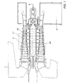
- Figure 1 shows a sectional view of an axial low-pressure compressor for a gas turbine with an air inlet at 1, a flow channel at 2 and an outlet at 3.
- the centre line of the rotor shaft is designated 4.
- the rotor 24 is, according to the figure, constructed from individual units which are bolted together to form a rotor body. According to the invention, the rotor may be made in one piece.
- Figure 2 shows an enlarged part of the flow channel in Figure 1 (dash-dotted square).
- the figure shows a design example with such an embodiment that the inventive concept can be applied.
- Figure 3 shows a sector of guide vanes with outer and inner interconnecting structural members.
- Figure 4 shows the sector according to Figure 3, seen axially in the direction of the arrow 25.
- the sector shown comprises five guide vanes.
- guide vanes 5 and attachment elements 6, 7 at both their ends constitute a whole in the form of an annular structural member.
- This is referred to as a guide vane ring.
- This ring is divided by means of radial sections into a number of sectors 9, the number being greater than two.
- Figures 3 and 4 show such a sector in two views.
- the sector comprises five guide vanes 5a-5e, held together by an outer structural member 6 and an inner structural member 7.
- the structural members 6, 7 enclose a damping material 8.
- Figure 2 shows a sector 9 of a guide vane ring in a position A, from which position A the sector 9 is inserted radially according to the arrow 10 into a position B.
- the insertion also comprises an axial displacement into a guide means 11 and in over a guide pin 12.
- the guide pin 12 fixes the sector in the correct angular position in the plane perpendicular to the direction of the rotor shaft.
- the guide means 11 fixes the sector radially.
- the guide vane sector 9 is fixed radially by the guide means 11 in the guide ring 13.
- the guide rings included in the compressor are bolted together axially in groups of rings or individually, which fixes the guide rings axially.
- Figure 1 shows a bolted joint 19 which interconnects guide rings 13, 20, 21 and further ring elements (not shown).
- Numeral 22 designates a blade mounted on the rotor disc 23.
- Numeral 24 designates the centre line of the rotor.
Landscapes
- Engineering & Computer Science (AREA)
- Mechanical Engineering (AREA)
- General Engineering & Computer Science (AREA)
- Structures Of Non-Positive Displacement Pumps (AREA)
Claims (15)
- Procédé de montage d'une turbomachine axiale, de préférence un compresseur basse pression pour une turbine à gaz, comportant un logement qui est construit sans avoir de ligne de partage suivant la direction longitudinale de la turbomachine, un rotor qui est construit d'une pièce ou qui peut être entièrement assemblé avant le montage et des anneaux formant aube de guidage qui sont divisés en secteurs guidés et fixés dans la position correcte par l'application d'anneaux (14) de guidage autour de chaque anneau constitué des secteurs d'anneaux formant aube de guidage, caractérisé en ce que le nombre de secteurs par anneau formant aube de guidage est supérieur à 2, et en ce que les anneaux formant aube de guidage sont montés en amenant les secteurs (9) radiaux en position, des interstices radiaux étant ménagés entre des secteurs adjacents d'anneaux formant aube de guidage.
- Procédé suivant la revendication 1, caractérisé en ce que les anneaux de guidage sont fixés axialement au moyen d'écrous (19) axiaux ou d'une autre forme quelconque d'éléments de fixation.
- Procédé suivant la revendication 1, caractérisé en ce que les secteurs, après avoir été amenés radialement en position, sont déplacés axialement en direction de l'anneau (13) de guidage monté précédemment, les secteurs (9) étant fixés radialement au moyen d'un guide (11) dans l'anneau (13) de guidage précédent.
- Procédé suivant la revendication 3, caractérisé en ce que chaque secteur (9) est fixé dans la position angulaire correcte dans le plan perpendiculaire à la direction de l'arbre de rotor, l'arbre de rotor servant de pivot, au moyen d'une broche (12) axiale ou d'un autre élément de guidage qui coopère avec le secteur lorsqu'il est fixé axialement à l'anneau (11) de guidage précédent.
- Procédé suivant la revendication 4, caractérisé en ce que les anneaux de guidage qui sont adaptés sur des secteurs positionnés fixent ceux-ci axialement.
- Procédé suivant la revendication 5, caractérisé en ce que des anneaux de guidage qui sont adaptés sur des secteurs positionnés ont des surfaces de guidage qui sont adaptées à des surfaces de guidage dans les secteurs et qui fixent radialement les secteurs.
- Procédé suivant la revendication 6, caractérisé en ce que les anneaux de guidage sont fixés axialement au moyen d'écrous axiaux ou d'une autre forme d'éléments de fixation.
- Procédé suivant la revendication 7, caractérisé en ce que les anneaux de guidage sont guidés radialement les uns contre les autres.
- Turbomachine axiale, de préférence compresseur basse pression pour une turbine à gaz, comportant un logement construit sans avoir de ligne de partition suivant la direction longitudinale de la turbomachine, comportant un rotor qui peut être construit d'une pièce et comportant des anneaux formant aube de guidage divisés en secteurs guidés et fixés dans la position correcte par des anneaux (14) de guidage autour de chaque anneau constitué de secteurs d'anneaux formant aube de guidage, caractérisée en ce que les anneaux formant aube de guidage sont divisés radialement en plus de deux secteurs (9) d'anneaux formant aube de guidage, des interstices radiaux étant ménagés entre des secteurs adjacents d'anneaux formant aube de guidage.
- Turbomachine axiale suivant la revendication 9, caractérisée en ce que les anneaux de guidage sont fixés axialement au moyen de joints à écrous (19) ou par toute autre forme d'éléments de fixation.
- Turbomachine axiale suivant la revendication 10, caractérisée en ce que les secteurs sont guidés et fixés dans l'anneau (13) de guidage de l'étage précédent.
- Turbomachine axiale suivant la revendication 11, caractérisée en ce qu'une broche (12) de guidage axial par secteur ou un autre élément de guidage fixe les secteurs dans l'anneau (13) de guidage précédent en une position angulaire définie dans le plan perpendiculaire à la direction de l'arbre de rotor, l'arbre de rotor formant pivot.
- Turbomachine axiale suivant la revendication 12, caractérisée en ce que l'anneau (14) de guidage fixe les secteurs positionnés axialement en coopération avec l'anneau (13) de guidage précédent.
- Turbomachine axiale suivant la revendication 13, caractérisée en ce que l'anneau de guidage comporte des surfaces de guidage qui sont guidées contre des surfaces de guidage correspondantes sur les secteurs lorsque l'anneau de guidage est monté axialement.
- Turbomachine axiale suivant la revendication 14, caractérisée en ce que les anneaux de guidage sont guidés radialement les uns contre les autres par l'intermédiaire de surfaces (15, 26) de guidage.
Applications Claiming Priority (3)
| Application Number | Priority Date | Filing Date | Title |
|---|---|---|---|
| SE9201083A SE500743C2 (sv) | 1992-04-01 | 1992-04-01 | Sätt och anordning för montering av axialströmningsmaskin |
| SE9201083 | 1992-04-01 | ||
| PCT/SE1993/000273 WO1993020334A1 (fr) | 1992-04-01 | 1993-03-30 | Montage d'une turbomachine axiale |
Publications (2)
| Publication Number | Publication Date |
|---|---|
| EP0633976A1 EP0633976A1 (fr) | 1995-01-18 |
| EP0633976B1 true EP0633976B1 (fr) | 1998-05-20 |
Family
ID=20385870
Family Applications (1)
| Application Number | Title | Priority Date | Filing Date |
|---|---|---|---|
| EP93908246A Expired - Lifetime EP0633976B1 (fr) | 1992-04-01 | 1993-03-30 | Montage d'une turbomachine axiale |
Country Status (8)
| Country | Link |
|---|---|
| US (1) | US5564897A (fr) |
| EP (1) | EP0633976B1 (fr) |
| JP (1) | JPH07505459A (fr) |
| DE (1) | DE69318707T2 (fr) |
| DK (1) | DK0633976T3 (fr) |
| ES (1) | ES2118951T3 (fr) |
| SE (1) | SE500743C2 (fr) |
| WO (1) | WO1993020334A1 (fr) |
Families Citing this family (23)
| Publication number | Priority date | Publication date | Assignee | Title |
|---|---|---|---|---|
| US5462403A (en) * | 1994-03-21 | 1995-10-31 | United Technologies Corporation | Compressor stator vane assembly |
| SE511813C2 (sv) | 1996-10-18 | 1999-11-29 | Atlas Copco Tools Ab | Axialflödesturbin |
| EP0844369B1 (fr) * | 1996-11-23 | 2002-01-30 | ROLLS-ROYCE plc | Assemblage d'un rotor à aubes et de son carter |
| US5788456A (en) * | 1997-02-21 | 1998-08-04 | Dresser-Rand Company | Turbine diaphragm assembly and method thereof |
| US5797725A (en) * | 1997-05-23 | 1998-08-25 | Allison Advanced Development Company | Gas turbine engine vane and method of manufacture |
| JPH11343807A (ja) | 1998-06-01 | 1999-12-14 | Mitsubishi Heavy Ind Ltd | 蒸気タービンの連結静翼 |
| US6209198B1 (en) * | 1998-12-16 | 2001-04-03 | General Electric Company | Method of assembling a variable stator vane assembly |
| FR2832179B1 (fr) * | 2001-11-14 | 2004-02-27 | Snecma Moteurs | Stator d'une machine et procedes de montage et demontage |
| CN100406684C (zh) | 2001-11-20 | 2008-07-30 | 阿尔斯通技术有限公司 | 气体涡轮组件 |
| US6843638B2 (en) | 2002-12-10 | 2005-01-18 | Honeywell International Inc. | Vane radial mounting apparatus |
| RU2335637C2 (ru) * | 2003-05-07 | 2008-10-10 | Снекма Мотер | Статор турбомашины и способы его сборки и разборки |
| CA2478623C (fr) * | 2003-05-07 | 2011-07-19 | Snecma Moteurs | Stator de machine et methodes de montage et de demontage |
| DE102008005943A1 (de) | 2007-01-24 | 2008-07-31 | Alstom Technology Ltd. | Gasturbogruppe mit verbesserter Abdichtung der Leitbeschaufelung |
| CH700001A1 (de) | 2008-11-20 | 2010-05-31 | Alstom Technology Ltd | Laufschaufelanordnung, insbesondere für eine gasturbine. |
| US8061969B2 (en) * | 2008-11-28 | 2011-11-22 | Pratt & Whitney Canada Corp. | Mid turbine frame system for gas turbine engine |
| US8099962B2 (en) * | 2008-11-28 | 2012-01-24 | Pratt & Whitney Canada Corp. | Mid turbine frame system and radial locator for radially centering a bearing for gas turbine engine |
| US8347500B2 (en) * | 2008-11-28 | 2013-01-08 | Pratt & Whitney Canada Corp. | Method of assembly and disassembly of a gas turbine mid turbine frame |
| US8347635B2 (en) * | 2008-11-28 | 2013-01-08 | Pratt & Whitey Canada Corp. | Locking apparatus for a radial locator for gas turbine engine mid turbine frame |
| US20100132371A1 (en) * | 2008-11-28 | 2010-06-03 | Pratt & Whitney Canada Corp. | Mid turbine frame system for gas turbine engine |
| US8091371B2 (en) * | 2008-11-28 | 2012-01-10 | Pratt & Whitney Canada Corp. | Mid turbine frame for gas turbine engine |
| US8245518B2 (en) * | 2008-11-28 | 2012-08-21 | Pratt & Whitney Canada Corp. | Mid turbine frame system for gas turbine engine |
| US20100132377A1 (en) * | 2008-11-28 | 2010-06-03 | Pratt & Whitney Canada Corp. | Fabricated itd-strut and vane ring for gas turbine engine |
| US9333603B1 (en) * | 2015-01-28 | 2016-05-10 | United Technologies Corporation | Method of assembling gas turbine engine section |
Family Cites Families (10)
| Publication number | Priority date | Publication date | Assignee | Title |
|---|---|---|---|---|
| GB589541A (en) * | 1941-09-22 | 1947-06-24 | Hayne Constant | Improvements in axial flow turbines, compressors and the like |
| GB666537A (en) * | 1949-08-27 | 1952-02-13 | Armstrong Siddeley Motors Ltd | Mounting of the stator blades of a gaseous fluid turbine |
| DE2121707C3 (de) * | 1971-05-03 | 1974-06-20 | Motoren- Und Turbinen-Union Friedrichshafen Gmbh, 7990 Friedrichshafen | Leitschaufelkranz |
| US3817655A (en) * | 1972-11-22 | 1974-06-18 | Carrier Corp | Stator blade mounting structure for turbomachines |
| US3892497A (en) * | 1974-05-14 | 1975-07-01 | Westinghouse Electric Corp | Axial flow turbine stationary blade and blade ring locking arrangement |
| SE406624B (sv) * | 1977-07-12 | 1979-02-19 | Stal Laval Turbin Ab | Turbomaskin |
| DE3003470C2 (de) * | 1980-01-31 | 1982-02-25 | MTU Motoren- und Turbinen-Union München GmbH, 8000 München | Turbinenleitschaufelaufhängung für Gasturbinenstrahltriebwerke |
| FR2552159B1 (fr) * | 1983-09-21 | 1987-07-10 | Snecma | Dispositif de liaison et d'etancheite de secteurs d'aubes de stator de turbine |
| US4648792A (en) * | 1985-04-30 | 1987-03-10 | United Technologies Corporation | Stator vane support assembly |
| US5127797A (en) * | 1990-09-12 | 1992-07-07 | United Technologies Corporation | Compressor case attachment means |
-
1992
- 1992-04-01 SE SE9201083A patent/SE500743C2/sv unknown
-
1993
- 1993-03-30 US US08/313,133 patent/US5564897A/en not_active Expired - Fee Related
- 1993-03-30 JP JP5517373A patent/JPH07505459A/ja active Pending
- 1993-03-30 ES ES93908246T patent/ES2118951T3/es not_active Expired - Lifetime
- 1993-03-30 WO PCT/SE1993/000273 patent/WO1993020334A1/fr not_active Ceased
- 1993-03-30 EP EP93908246A patent/EP0633976B1/fr not_active Expired - Lifetime
- 1993-03-30 DE DE69318707T patent/DE69318707T2/de not_active Expired - Fee Related
- 1993-03-30 DK DK93908246T patent/DK0633976T3/da active
Also Published As
| Publication number | Publication date |
|---|---|
| WO1993020334A1 (fr) | 1993-10-14 |
| SE500743C2 (sv) | 1994-08-22 |
| SE9201083L (sv) | 1993-10-02 |
| US5564897A (en) | 1996-10-15 |
| JPH07505459A (ja) | 1995-06-15 |
| DE69318707T2 (de) | 1998-12-10 |
| SE9201083D0 (sv) | 1992-04-01 |
| DE69318707D1 (de) | 1998-06-25 |
| EP0633976A1 (fr) | 1995-01-18 |
| ES2118951T3 (es) | 1998-10-01 |
| DK0633976T3 (da) | 1999-03-15 |
Similar Documents
| Publication | Publication Date | Title |
|---|---|---|
| EP0633976B1 (fr) | Montage d'une turbomachine axiale | |
| US3326523A (en) | Stator vane assembly having composite sectors | |
| KR100379728B1 (ko) | 로터조립체용시라우드및로터조립체시라우드용블레이드외부공기시일 | |
| US3728041A (en) | Fluidic seal for segmented nozzle diaphragm | |
| US3745629A (en) | Method of determining optimal shapes for stator blades | |
| US4767260A (en) | Stator vane platform cooling means | |
| US3520635A (en) | Turbomachine shroud assembly | |
| US20180238172A1 (en) | Turbine engine turbine rotor with ventilation by counterbore | |
| US3262635A (en) | Turbomachine sealing means | |
| US3837761A (en) | Guide vanes for supersonic turbine blades | |
| US3182955A (en) | Construction of turbomachinery blade elements | |
| US7614845B2 (en) | Turbomachine inner casing fitted with a heat shield | |
| US3519366A (en) | Turbine diaphragm seal structure | |
| EP3513040B1 (fr) | Technique d'équilibrage d'un rotor de compresseur d'une turbine à gaz | |
| JP2018513299A (ja) | 好ましくは有機ランキン・サイクルorcプラントのための多段タービン | |
| US10876406B2 (en) | Radial turbomachine | |
| US3893782A (en) | Turbine blade damping | |
| US2458149A (en) | Rotor construction for turbines | |
| US3034762A (en) | Blade damping means | |
| EP3693541B1 (fr) | Disque de rotor de turbine à gaz doté d'une fonctionnalité de protection de grille | |
| US20100158675A1 (en) | Turbomachine rotor having blades of composite material provided with metal labyrinth teeth | |
| US3751182A (en) | Guide vanes for supersonic turbine blades | |
| US3367630A (en) | Continuous shroud structure | |
| EP3222811A1 (fr) | Amortissement des vibrations dans une turbine à gaz | |
| US2996280A (en) | Heat shield |
Legal Events
| Date | Code | Title | Description |
|---|---|---|---|
| PUAI | Public reference made under article 153(3) epc to a published international application that has entered the european phase |
Free format text: ORIGINAL CODE: 0009012 |
|
| 17P | Request for examination filed |
Effective date: 19941022 |
|
| AK | Designated contracting states |
Kind code of ref document: A1 Designated state(s): CH DE DK ES GB IT LI NL |
|
| 17Q | First examination report despatched |
Effective date: 19950710 |
|
| GRAG | Despatch of communication of intention to grant |
Free format text: ORIGINAL CODE: EPIDOS AGRA |
|
| GRAG | Despatch of communication of intention to grant |
Free format text: ORIGINAL CODE: EPIDOS AGRA |
|
| GRAH | Despatch of communication of intention to grant a patent |
Free format text: ORIGINAL CODE: EPIDOS IGRA |
|
| GRAH | Despatch of communication of intention to grant a patent |
Free format text: ORIGINAL CODE: EPIDOS IGRA |
|
| GRAA | (expected) grant |
Free format text: ORIGINAL CODE: 0009210 |
|
| AK | Designated contracting states |
Kind code of ref document: B1 Designated state(s): CH DE DK ES GB IT LI NL |
|
| REG | Reference to a national code |
Ref country code: CH Ref legal event code: EP |
|
| REF | Corresponds to: |
Ref document number: 69318707 Country of ref document: DE Date of ref document: 19980625 |
|
| ITF | It: translation for a ep patent filed | ||
| REG | Reference to a national code |
Ref country code: CH Ref legal event code: NV Representative=s name: PATENTANWAELTE SCHAAD, BALASS, MENZL & PARTNER AG |
|
| REG | Reference to a national code |
Ref country code: ES Ref legal event code: FG2A Ref document number: 2118951 Country of ref document: ES Kind code of ref document: T3 |
|
| REG | Reference to a national code |
Ref country code: DK Ref legal event code: T3 |
|
| PLBE | No opposition filed within time limit |
Free format text: ORIGINAL CODE: 0009261 |
|
| STAA | Information on the status of an ep patent application or granted ep patent |
Free format text: STATUS: NO OPPOSITION FILED WITHIN TIME LIMIT |
|
| PG25 | Lapsed in a contracting state [announced via postgrant information from national office to epo] |
Ref country code: LI Free format text: LAPSE BECAUSE OF NON-PAYMENT OF DUE FEES Effective date: 19990331 Ref country code: DK Free format text: LAPSE BECAUSE OF NON-PAYMENT OF DUE FEES Effective date: 19990331 Ref country code: CH Free format text: LAPSE BECAUSE OF NON-PAYMENT OF DUE FEES Effective date: 19990331 |
|
| 26N | No opposition filed | ||
| PG25 | Lapsed in a contracting state [announced via postgrant information from national office to epo] |
Ref country code: NL Free format text: LAPSE BECAUSE OF NON-PAYMENT OF DUE FEES Effective date: 19991001 |
|
| REG | Reference to a national code |
Ref country code: CH Ref legal event code: PL |
|
| NLV4 | Nl: lapsed or anulled due to non-payment of the annual fee |
Effective date: 19991001 |
|
| PGFP | Annual fee paid to national office [announced via postgrant information from national office to epo] |
Ref country code: DE Payment date: 19991231 Year of fee payment: 8 |
|
| REG | Reference to a national code |
Ref country code: DK Ref legal event code: EBP |
|
| PGFP | Annual fee paid to national office [announced via postgrant information from national office to epo] |
Ref country code: ES Payment date: 20000322 Year of fee payment: 8 |
|
| PGFP | Annual fee paid to national office [announced via postgrant information from national office to epo] |
Ref country code: GB Payment date: 20000329 Year of fee payment: 8 |
|
| PG25 | Lapsed in a contracting state [announced via postgrant information from national office to epo] |
Ref country code: GB Free format text: LAPSE BECAUSE OF NON-PAYMENT OF DUE FEES Effective date: 20010330 |
|
| PG25 | Lapsed in a contracting state [announced via postgrant information from national office to epo] |
Ref country code: ES Free format text: LAPSE BECAUSE OF NON-PAYMENT OF DUE FEES Effective date: 20010331 |
|
| GBPC | Gb: european patent ceased through non-payment of renewal fee |
Effective date: 20010330 |
|
| PG25 | Lapsed in a contracting state [announced via postgrant information from national office to epo] |
Ref country code: DE Free format text: LAPSE BECAUSE OF NON-PAYMENT OF DUE FEES Effective date: 20020101 |
|
| REG | Reference to a national code |
Ref country code: ES Ref legal event code: FD2A Effective date: 20030203 |
|
| PG25 | Lapsed in a contracting state [announced via postgrant information from national office to epo] |
Ref country code: IT Free format text: LAPSE BECAUSE OF NON-PAYMENT OF DUE FEES Effective date: 20050330 |