EP0633968B1 - Systeme de verrouillage pour levier d'outillage de vehicule de travail - Google Patents
Systeme de verrouillage pour levier d'outillage de vehicule de travail Download PDFInfo
- Publication number
- EP0633968B1 EP0633968B1 EP19940902343 EP94902343A EP0633968B1 EP 0633968 B1 EP0633968 B1 EP 0633968B1 EP 19940902343 EP19940902343 EP 19940902343 EP 94902343 A EP94902343 A EP 94902343A EP 0633968 B1 EP0633968 B1 EP 0633968B1
- Authority
- EP
- European Patent Office
- Prior art keywords
- gate
- rotatable shaft
- axis
- work vehicle
- slot
- Prior art date
- Legal status (The legal status is an assumption and is not a legal conclusion. Google has not performed a legal analysis and makes no representation as to the accuracy of the status listed.)
- Expired - Lifetime
Links
- 230000001419 dependent effect Effects 0.000 description 1
- 238000004519 manufacturing process Methods 0.000 description 1
Images


Classifications
-
- E—FIXED CONSTRUCTIONS
- E02—HYDRAULIC ENGINEERING; FOUNDATIONS; SOIL SHIFTING
- E02F—DREDGING; SOIL-SHIFTING
- E02F9/00—Component parts of dredgers or soil-shifting machines, not restricted to one of the kinds covered by groups E02F3/00 - E02F7/00
- E02F9/24—Safety devices, e.g. for preventing overload
-
- E—FIXED CONSTRUCTIONS
- E02—HYDRAULIC ENGINEERING; FOUNDATIONS; SOIL SHIFTING
- E02F—DREDGING; SOIL-SHIFTING
- E02F9/00—Component parts of dredgers or soil-shifting machines, not restricted to one of the kinds covered by groups E02F3/00 - E02F7/00
- E02F9/20—Drives; Control devices
- E02F9/2004—Control mechanisms, e.g. control levers
-
- G—PHYSICS
- G05—CONTROLLING; REGULATING
- G05G—CONTROL DEVICES OR SYSTEMS INSOFAR AS CHARACTERISED BY MECHANICAL FEATURES ONLY
- G05G5/00—Means for preventing, limiting or returning the movements of parts of a control mechanism, e.g. locking controlling member
- G05G5/06—Means for preventing, limiting or returning the movements of parts of a control mechanism, e.g. locking controlling member for holding members in one or a limited number of definite positions only
- G05G5/08—Interlocking of members, e.g. locking member in a particular position before or during the movement of another member
-
- Y—GENERAL TAGGING OF NEW TECHNOLOGICAL DEVELOPMENTS; GENERAL TAGGING OF CROSS-SECTIONAL TECHNOLOGIES SPANNING OVER SEVERAL SECTIONS OF THE IPC; TECHNICAL SUBJECTS COVERED BY FORMER USPC CROSS-REFERENCE ART COLLECTIONS [XRACs] AND DIGESTS
- Y10—TECHNICAL SUBJECTS COVERED BY FORMER USPC
- Y10T—TECHNICAL SUBJECTS COVERED BY FORMER US CLASSIFICATION
- Y10T70/00—Locks
- Y10T70/50—Special application
- Y10T70/5611—For control and machine elements
- Y10T70/569—Lever
- Y10T70/5717—Multiple
- Y10T70/5721—Externally mounted locking device
-
- Y—GENERAL TAGGING OF NEW TECHNOLOGICAL DEVELOPMENTS; GENERAL TAGGING OF CROSS-SECTIONAL TECHNOLOGIES SPANNING OVER SEVERAL SECTIONS OF THE IPC; TECHNICAL SUBJECTS COVERED BY FORMER USPC CROSS-REFERENCE ART COLLECTIONS [XRACs] AND DIGESTS
- Y10—TECHNICAL SUBJECTS COVERED BY FORMER USPC
- Y10T—TECHNICAL SUBJECTS COVERED BY FORMER US CLASSIFICATION
- Y10T74/00—Machine element or mechanism
- Y10T74/20—Control lever and linkage systems
- Y10T74/20207—Multiple controlling elements for single controlled element
- Y10T74/20238—Interlocked
-
- Y—GENERAL TAGGING OF NEW TECHNOLOGICAL DEVELOPMENTS; GENERAL TAGGING OF CROSS-SECTIONAL TECHNOLOGIES SPANNING OVER SEVERAL SECTIONS OF THE IPC; TECHNICAL SUBJECTS COVERED BY FORMER USPC CROSS-REFERENCE ART COLLECTIONS [XRACs] AND DIGESTS
- Y10—TECHNICAL SUBJECTS COVERED BY FORMER USPC
- Y10T—TECHNICAL SUBJECTS COVERED BY FORMER US CLASSIFICATION
- Y10T74/00—Machine element or mechanism
- Y10T74/20—Control lever and linkage systems
- Y10T74/20576—Elements
- Y10T74/20582—Levers
- Y10T74/2063—Stops
Definitions
- This invention relates generally to a locking mechanism for implement controlling components of a work vehicle as known from US-A-4 036 077.
- Various heavy duty work vehicles have a plurality of implement controlling components for manipulating an implement of the work vehicle.
- An example of such as vehicle would be a wheel loader which has a plurality of levers for manipulating the earth moving bucket through a multiplicity of positions.
- a common problem in the manufacture of such massive vehicles is to easily control a plurality of bucket movements by as few operator actions as possible. Placement and position of control levers, one relative to others, also becomes a problem since it is most common during various bucket maneuvers to simultaneously or generally simultaneously operate several controlling levers. Overall efficiency of vehicle operations often depends on the operator's skill in adjusting and manipulating the correct levers in the correct sequence at the optimum times.
- wheel loaders it is desirable to lock a plurality of controlling components at a preselected position for a desirable time during manipulation of other controlling components. For example, locking of the lift and tilt kickout controlling components. To increase efficiency of operation, it is desirable for the operator to initiate locking or releasing of these components in response to as few operator movements as possible.
- the present invention is directed to overcoming one or more of the problems as set forth above.
- a work vehicle has a control assembly which has a plurality of implement actuation levers.
- Each actuation lever is associated with a respective actuating element for controlling respective movements of an implement of the work vehicle in response to pivotal movement of the actuating elements responsive to movement of the respective actuation lever.
- the actuating elements each have a longitudinal axis, a first end portion connected to and pivotally connected to a frame and a latchable element extending generally along the actuating element axis and outwardly therefrom.
- a gate of the invention has a cam surface and a plurality of spaced apart slots. Each slot has an axis extending in a first direction and a latch opening communicating with the slot and extending a second direction transverse the slot.
- Each slot is of a size sufficient to receive a respective latchable element for movement along the slot in response to movement of said respective lever.
- the gate is moveable in the second direction between a first position at which the latchable elements are positioned within a respective slot and free to move along said slot and a second position at which the latchable elements are within respective latch openings and maintaining said latchable element and associated actuating element against pivotal movement.
- the gate is biased in the second direction and a cam follower is contactable with the cam surface of the gate and is moveable along the cam surface for moving the gate between the first and second positions.
- a first rotatable shaft has a longitudinal axis and is connected to the cam follower and is rotatable for controllably moving the cam follower along the cam surface of the gate.
- a second rotatable shaft has a longitudinal axis and extends generally parallel to said first rotatable shaft.
- a first link is connected to the first rotatable shaft, extends transverse the first rotatable shaft axis and is moveable therewith.
- a second link is connected to the second rotatable shaft, extends transverse the second rotatable shaft axis and is moveable therewith.
- a connecting link has first and second end portions. The first end portion is pivotally connected to said first link and the second end portion is pivotally connected to the second link.
- a lock actuation lever is connected to the second rotatable shaft for controllably rotating the second rotatable shaft and responsively moving the gate and locking and releasing the associated actuating elements.
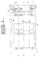
- a work vehicle for example an excavator or a backhoe, has a bucket whose movement is controlled by a plurality of implement actuation levers each of which are associated with a respective actuating element 10,12,14.
- the actuating elements each have a longitudinal axis, a first end portion 16,18,20 pivotally connected to a frame 22 and a latchable element 24,26,28 extending generally along the actuating element axis and outwardly from a second end portion 30, 32,34 of the respective actuating element 10,12,14.
- the actuating elements 10,12,14 can be, for example, hydraulic pilot cylinders or solenoid valves. Such an arrangement is well known in the art of excavators, backhoes and other work vehicles.
- the locking system of this invention has a gate 36 which has a cam surface 38 (better seen in Fig. 4) and a plurality of spaced part slots 40,42,44.
- Each slot 40,42,44 has an axis extending in a first direction with a respective latch opening 46,48,50 communicating with its slot and extending in a second direction transverse the slot axis.
- Each slot 40,42,44 is of a size sufficient to receive a respective latchable element 24,26,28 for movement along the respective slot 40,42,44 in response to movement of said respective lever.
- the gate 36 is moveable in the second direction between a first position at which the latchable elements 24,26,28 are positioned with a respective slot 40,42,44 and free to move along said slot 40,42,44 and a second position, as shown in Fig. 3, at which the latchable 24,26,28 elements are within respective latch openings 46,48,50 and maintaining said latchable elements 24,26,28 and associated actuating elements 10,12,14 against pivotal movement.
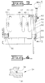
- Means such as one or more helical springs 52 are associated with the gate 36 for biasing the gate 36 in the second direction.
- the second direction is transverse the direction of the slots 40,42,44 and the actual direction of biasing will be dependent upon which side of the gate 36 the spring(s) 52 are located.
- the spring(s) 52 will bias the gate toward its locked position.
- a cam follower 54 is contactable with the cam surface 38, as shown in Figs. 2 and 4, and is moveable along the cam surface for moving the gate 36 between the first and second positions.
- a first rotatable shaft 58 has a longitudinal axis and is connected to the cam follower 54 and is rotatable for controllably moving the cam follower 54 along the cam surface of the gate 36.
- a first link 60 is connected to the first rotatable shaft 58, extends transverse the longitudinal axis for the first rotatable shaft 58 and is moveable therewith.
- a second rotatable shaft 62 has a longitudinal axis extending generally parallel to said first rotatable shaft 58. Both of the shafts 58,62 are rotatably connected to the frame 22.
- a second link 64 is connected to the second rotatable shaft 62, extends transverse the second rotatable shaft axis and is moveable therewith.
- a connecting link 66 has first and second end portions 68,70.
- the first end portion 68 is pivotally connected to the first link 60 and the second end portion 70 is pivotally connected to the second link 64.
- a lock actuation lever 72 is connected to the second rotatable shaft 62 for controllably rotating the second rotatable shaft 62 and responsively moving the gate 36 and locking and releasing the associated actuating elements 10,12,14.
- the actuating elements 10,12,14 are pivotally connected to the frame 22 and pivotally moveable about a common axis.
- the axis of the actuating elements 10,12,14 at the locked position are at an angle in the range of about 0 to about 45 degrees relative to horizontal, more preferably at an angle of about 15 degrees.
- the latch openings 46,48,50 are each positioned at generally the mid point between the ends of their gate slot 40,42,44. However, in some cases the latch openings 46,48,50 may desirably be positioned at different preselected elevations relative one the other as measured along the cam surface from one end of the slots 40,42,44
- lever 72 In the operation of the apparatus of this invention, the operator can move lever 72 to lock actuation elements 10,12 and 14 at their position when lever 72 is moved. Movement of lever 72 rotates shaft 62 which in turn rotates the second link 64. As link 64 moves the connecting link 66 causes the first link 60 to move which rotates the first shaft 58.
- Rotation of the first shaft 58 causes follower 54 to move along the cam surface 38 which urges the gate to shift in the second direction and cause latch elements 24,26, and 28 to be received into respective latch openings 46,48,50 and be maintained by the gate and prevent pivotal movement of the actuating elements 10,12, and 14.
- actuating elements can be different from the three shown in the drawings and that the gate can be constructed with different arrangements of slots or locations of latch openings relative to slot lengths.
Landscapes
- Engineering & Computer Science (AREA)
- Mining & Mineral Resources (AREA)
- Civil Engineering (AREA)
- General Engineering & Computer Science (AREA)
- Structural Engineering (AREA)
- Physics & Mathematics (AREA)
- General Physics & Mathematics (AREA)
- Automation & Control Theory (AREA)
- Operation Control Of Excavators (AREA)
- Component Parts Of Construction Machinery (AREA)
- Mechanical Control Devices (AREA)
Abstract
Claims (7)
- Dans un ensemble de commande de véhicule de travail comportant une pluralité de leviers d'actionnement d'organe, dont chacun est associé à un élément d'actionnement respectif (10, 12, 14) pour commander les mouvements respectifs d'un organe du véhicule de travail en réponse à un mouvement de pivotement des éléments d'actionnement (10, 12, 14) en réponse au mouvement du levier d'actionnement respectif, lesdits éléments d'actionnement (10, 12, 14) ayant, chacun, un axe longitudinal, une première partie d'extrémité (16, 18, 20) connectée à pivotement à un cadre (22) et un élément verrouillable (24, 26, 28) s'étendant dans son ensemble le long de l'axe de l'élément d'actionnement et vers l'extérieur à partir d'une seconde partie d'extrémité (30, 32, 34) de l'élément d'actionnement, le perfectionnement comprenant :une porte (36) ayant une surface de came (38) et une pluralité de fentes espacées (40, 42, 44), chaque fente (40, 42, 44) ayant un axe s'étendant dans une première direction, une ouverture de verrou communiquant avec ladite fente et s'étendant dans une seconde direction transversale par rapport à l'axe de la fente, chaque fente (40, 42, 44) ayant des dimensions suffisantes pour recevoir un élément verrouillable respectif (24, 26, 28) pour un mouvement le long de la fente en réponse au mouvement dudit levier respectif, et ladite porte (36) étant déplaçable dans la seconde direction entre une première position, pour laquelle les éléments verrouillables (24, 26, 28) sont positionnés à l'intérieur d'une fente respective (40, 42, 44) et libres de se déplacer le long de ladite fente (40, 42, 44), et une seconde position pour laquelle les éléments verrouillables sont à l'intérieur des ouvertures respectives (46, 48, 50) de verrou et empêchent un mouvement de pivotement dudit élément verrouillable (24, 26, 28) et des éléments d'actionnement associés (10, 12, 14) ;des moyens (52) pour pousser la porte dans la seconde direction ;un suiveur de came (54) pouvant entrer en contact avec la surface de came (56) de la porte (36) et déplaçable le long de la surface de came pour déplacer la porte (36) entre les première et seconde positions ;un premier arbre (58) pouvant tourner ayant un axe longitudinal et connecté au suiveur de came (54) et pouvant tourner pour déplacer, sous commande, le suiveur de came (54) le long de la surface de came (56) de la porte (36) ;un premier maillon (60) connecté au premier arbre (58) pouvant tourner, s'étendant transversalement à l'axe du premier arbre pouvant tourner et pouvant se déplacer avec celui-ci ;un second arbre (62) pouvant tourner ayant un axe longitudinal s'étendant, dans son ensemble, parallèlement audit premier arbre (58) pouvant tourner ;un second maillon (64) connecté au second arbre (62) pouvant tourner, s'étendant transversalement à l'axe du second arbre pouvant tourner et pouvant se déplacer avec ce dernier ;un maillon (66) de connexion ayant des première et seconde parties d'extrémités (68, 70), ladite première partie d'extrémité (68) étant connectée à pivotement audit premier maillon (60) et ladite seconde partie d'extrémité (70) étant connectée à pivotement audit second maillon (64) ; etun levier (72) d'actionnement de verrou connecté au second arbre (62) pouvant tourner pour faire tourner, sous commande, le second arbre (62) pouvant tourner et, en réponse, déplacer la porte (36) et bloquer et libérer les éléments d'actionnement associés (10, 12, 14).
- Ensemble de commande de véhicule de travail selon la revendication 1, dans lequel les éléments d'actionnement (10, 12, 14) sont connectés à pivotement au cadre (22) et déplaçables par pivotement autour d'un axe commun.
- Ensemble de commande de véhicule de travail selon la revendication 1, dans lequel l'axe des éléments d'actionnement (10, 12, 14) forme, en position verrouillée, un angle dans la gamme d'environ 0 à 45° par rapport à l'horizontale.
- Ensemble de commande de véhicule de travail selon la revendication 1, dans lequel les ouvertures de verrou (46, 48, 50) sont, chacune, positionnées, dans leur ensemble, au point médian de leur fente (40, 42, 44) de porte respective.
- Ensemble de commande de véhicule de travail selon la revendication 1, dans lequel une partie des ouvertures (46, 48, 50) de verrou est à des hauteurs présélectionnées différentes les unes par rapport aux autres comme mesuré le long de la surface de came à partir d'une extrémité des fentes (40, 42, 44).
- Ensemble de commande de véhicule de travail selon la revendication 1, dans lequel le moyen de poussée (52) de la porte (36) est un ressort poussant la porte (36) vers sa position verrouillée.
- Ensemble de commande de véhicule de travail selon la revendication 1, dans lequel les axes des premier et second arbres pouvant tourner et une surface de la porte (36) s'étendent, dans leur ensemble, perpendiculairement à l'axe de l'élément d'actionnement.
Applications Claiming Priority (3)
| Application Number | Priority Date | Filing Date | Title |
|---|---|---|---|
| US08/016,226 US5325733A (en) | 1993-02-11 | 1993-02-11 | Work vehicle implement lever lock |
| PCT/US1993/011322 WO1994018400A1 (fr) | 1993-02-11 | 1993-11-22 | Systeme de verrouillage pour levier d'outillage de vehicule de travail |
| US16226 | 1996-04-26 |
Publications (2)
| Publication Number | Publication Date |
|---|---|
| EP0633968A1 EP0633968A1 (fr) | 1995-01-18 |
| EP0633968B1 true EP0633968B1 (fr) | 1997-01-02 |
Family
ID=21776023
Family Applications (1)
| Application Number | Title | Priority Date | Filing Date |
|---|---|---|---|
| EP19940902343 Expired - Lifetime EP0633968B1 (fr) | 1993-02-11 | 1993-11-22 | Systeme de verrouillage pour levier d'outillage de vehicule de travail |
Country Status (6)
| Country | Link |
|---|---|
| US (1) | US5325733A (fr) |
| EP (1) | EP0633968B1 (fr) |
| JP (1) | JP3373520B2 (fr) |
| AU (1) | AU5674294A (fr) |
| DE (1) | DE69307134D1 (fr) |
| WO (1) | WO1994018400A1 (fr) |
Families Citing this family (5)
| Publication number | Priority date | Publication date | Assignee | Title |
|---|---|---|---|---|
| US5595091A (en) * | 1995-04-28 | 1997-01-21 | Caterpillar Inc. | Restraint mechanism for a control lever |
| US5551265A (en) * | 1995-04-28 | 1996-09-03 | Caterpillar Inc. | Restraint mechanism for a control lever |
| DE19932286A1 (de) | 1999-07-10 | 2001-01-11 | Deere & Co | Betätigungsvorrichtung |
| US20030012597A1 (en) * | 2001-07-16 | 2003-01-16 | Miller Darin R. | Work tool locking device |
| US6705135B2 (en) * | 2002-03-11 | 2004-03-16 | Bryan Witchey | Excavator lock |
Family Cites Families (17)
| Publication number | Priority date | Publication date | Assignee | Title |
|---|---|---|---|---|
| US589811A (en) * | 1897-09-14 | Blind-fastener | ||
| US2899167A (en) * | 1959-08-11 | elsner | ||
| US606484A (en) * | 1898-06-28 | Sash-fastener | ||
| US1234236A (en) * | 1914-09-08 | 1917-07-24 | Paul N Van Epp | Trolley-retriever. |
| FR511226A (fr) * | 1920-03-08 | 1920-12-20 | Gabriel De Longeville | Dispositif destiné à empecher le vol des voitures automobiles et autres véhicules analogues |
| US1564593A (en) * | 1924-03-22 | 1925-12-08 | William O Lawrence | Combined lock and latch |
| US1585144A (en) * | 1925-01-10 | 1926-05-18 | Alexis Kellner | Locking device for carriage doors |
| US1865581A (en) * | 1929-01-21 | 1932-07-05 | Dura Co | Combined door latch and kick-out assembly |
| US1828927A (en) * | 1930-07-28 | 1931-10-27 | Ferro Stamping & Mfg Company | Door latch mechanism |
| US1985653A (en) * | 1931-11-07 | 1934-12-25 | Reyrolle A & Co Ltd | Electric switch gear |
| US2094746A (en) * | 1935-03-21 | 1937-10-05 | Fred B Palmer | Automobile door latch |
| US2140570A (en) * | 1937-07-12 | 1938-12-20 | Young William | Door securing mechanism |
| US2131506A (en) * | 1937-11-02 | 1938-09-27 | Herman M Gasstrom | Lock |
| US2804331A (en) * | 1953-11-25 | 1957-08-27 | Maglum Soc | Latch for vehicle doors |
| US3858695A (en) * | 1974-02-06 | 1975-01-07 | Deere & Co | Transmission and brake interlock |
| JPS51105593A (en) * | 1975-03-13 | 1976-09-18 | Mitsubishi Heavy Ind Ltd | Tarensosarebaano anzensochi |
| US4222287A (en) | 1978-03-27 | 1980-09-16 | Fiat-Allis Construction Machinery, Inc. | Multiple control locking device |
-
1993
- 1993-02-11 US US08/016,226 patent/US5325733A/en not_active Expired - Lifetime
- 1993-11-22 AU AU56742/94A patent/AU5674294A/en not_active Abandoned
- 1993-11-22 JP JP51800694A patent/JP3373520B2/ja not_active Expired - Fee Related
- 1993-11-22 DE DE69307134T patent/DE69307134D1/de not_active Expired - Lifetime
- 1993-11-22 EP EP19940902343 patent/EP0633968B1/fr not_active Expired - Lifetime
- 1993-11-22 WO PCT/US1993/011322 patent/WO1994018400A1/fr not_active Ceased
Also Published As
| Publication number | Publication date |
|---|---|
| US5325733A (en) | 1994-07-05 |
| AU5674294A (en) | 1994-08-29 |
| WO1994018400A1 (fr) | 1994-08-18 |
| DE69307134D1 (de) | 1997-02-13 |
| JPH07505937A (ja) | 1995-06-29 |
| JP3373520B2 (ja) | 2003-02-04 |
| EP0633968A1 (fr) | 1995-01-18 |
Similar Documents
| Publication | Publication Date | Title |
|---|---|---|
| EP1676006B1 (fr) | Dispositif d'attache rapide pour outil d'excavateur | |
| US5735065A (en) | Area limiting excavation control system for construction machine | |
| US6132131A (en) | Attachment mounting/demounting device in working machinery | |
| US4548094A (en) | Handle control assembly | |
| EP0633968B1 (fr) | Systeme de verrouillage pour levier d'outillage de vehicule de travail | |
| AU2019275647B2 (en) | Attachment grade control for work vehicle | |
| US4646778A (en) | Valve control structure for working vehicle | |
| US20040182233A1 (en) | Hydraulic control apparatus for controlling hydraulic cylinder for implement | |
| CN118234909A (zh) | 快速耦合器自动锁定机构和方法 | |
| DE2341807C2 (de) | Steuerungseinrichtung | |
| US4222287A (en) | Multiple control locking device | |
| AU2019271992A1 (en) | Boom Lock | |
| EP3822416B1 (fr) | Engin de construction doté d'un bras de travail amélioré | |
| CA1284758C (fr) | Dispositif de neutralisation pour distributeur a tiroir | |
| JPH04203031A (ja) | レバーロック装置 | |
| US7357064B2 (en) | Hydraulic control system for a mobile piece of equipment | |
| US12497748B2 (en) | Attachment tool coupling assembly for a construction vehicle | |
| EP1018578B1 (fr) | Procede et appareil de verrouillage d'une machine | |
| EP4431666A1 (fr) | Engin de chantier | |
| KR100402328B1 (ko) | 스키드 스티어로더의 주행시 페달조작 방지장치 | |
| US4182195A (en) | Transmission shift control lock assembly | |
| JPH0327098Y2 (fr) | ||
| US4343588A (en) | Kickout bucket positioner | |
| CA1137928A (fr) | Positionneur pour godet de fouille | |
| JP3118747B2 (ja) | 操作系のロック装置 |
Legal Events
| Date | Code | Title | Description |
|---|---|---|---|
| PUAI | Public reference made under article 153(3) epc to a published international application that has entered the european phase |
Free format text: ORIGINAL CODE: 0009012 |
|
| AK | Designated contracting states |
Kind code of ref document: A1 Designated state(s): DE FR SE |
|
| 17P | Request for examination filed |
Effective date: 19941230 |
|
| GRAG | Despatch of communication of intention to grant |
Free format text: ORIGINAL CODE: EPIDOS AGRA |
|
| 17Q | First examination report despatched |
Effective date: 19960514 |
|
| GRAH | Despatch of communication of intention to grant a patent |
Free format text: ORIGINAL CODE: EPIDOS IGRA |
|
| GRAH | Despatch of communication of intention to grant a patent |
Free format text: ORIGINAL CODE: EPIDOS IGRA |
|
| GRAA | (expected) grant |
Free format text: ORIGINAL CODE: 0009210 |
|
| AK | Designated contracting states |
Kind code of ref document: B1 Designated state(s): DE FR SE |
|
| REF | Corresponds to: |
Ref document number: 69307134 Country of ref document: DE Date of ref document: 19970213 |
|
| ET | Fr: translation filed | ||
| PG25 | Lapsed in a contracting state [announced via postgrant information from national office to epo] |
Ref country code: DE Effective date: 19970403 |
|
| PLBE | No opposition filed within time limit |
Free format text: ORIGINAL CODE: 0009261 |
|
| STAA | Information on the status of an ep patent application or granted ep patent |
Free format text: STATUS: NO OPPOSITION FILED WITHIN TIME LIMIT |
|
| 26N | No opposition filed | ||
| PGFP | Annual fee paid to national office [announced via postgrant information from national office to epo] |
Ref country code: FR Payment date: 20051104 Year of fee payment: 13 |
|
| PGFP | Annual fee paid to national office [announced via postgrant information from national office to epo] |
Ref country code: SE Payment date: 20051107 Year of fee payment: 13 |
|
| PG25 | Lapsed in a contracting state [announced via postgrant information from national office to epo] |
Ref country code: SE Free format text: LAPSE BECAUSE OF NON-PAYMENT OF DUE FEES Effective date: 20061123 |
|
| EUG | Se: european patent has lapsed | ||
| REG | Reference to a national code |
Ref country code: FR Ref legal event code: ST Effective date: 20070731 |
|
| PG25 | Lapsed in a contracting state [announced via postgrant information from national office to epo] |
Ref country code: FR Free format text: LAPSE BECAUSE OF NON-PAYMENT OF DUE FEES Effective date: 20061130 |