EP0633701A2 - Méthode et dispositif pour la compression d'un signal vidéo numérique - Google Patents
Méthode et dispositif pour la compression d'un signal vidéo numérique Download PDFInfo
- Publication number
- EP0633701A2 EP0633701A2 EP94110461A EP94110461A EP0633701A2 EP 0633701 A2 EP0633701 A2 EP 0633701A2 EP 94110461 A EP94110461 A EP 94110461A EP 94110461 A EP94110461 A EP 94110461A EP 0633701 A2 EP0633701 A2 EP 0633701A2
- Authority
- EP
- European Patent Office
- Prior art keywords
- image
- memory
- block
- identifier
- address
- Prior art date
- Legal status (The legal status is an assumption and is not a legal conclusion. Google has not performed a legal analysis and makes no representation as to the accuracy of the status listed.)
- Withdrawn
Links
Images
Classifications
-
- H—ELECTRICITY
- H04—ELECTRIC COMMUNICATION TECHNIQUE
- H04N—PICTORIAL COMMUNICATION, e.g. TELEVISION
- H04N19/00—Methods or arrangements for coding, decoding, compressing or decompressing digital video signals
- H04N19/90—Methods or arrangements for coding, decoding, compressing or decompressing digital video signals using coding techniques not provided for in groups H04N19/10-H04N19/85, e.g. fractals
- H04N19/94—Vector quantisation
-
- G—PHYSICS
- G06—COMPUTING; CALCULATING OR COUNTING
- G06T—IMAGE DATA PROCESSING OR GENERATION, IN GENERAL
- G06T9/00—Image coding
- G06T9/008—Vector quantisation
Definitions
- the invention relates to a method for the compression of a digitally encoded video image in connection with transmission, wherein image information is encoded as successive image blocks each consisting of n x m pixels, and an image block to be transmitted is compared with at least one other image block to determine the correspondence between them; and to a device for the compression of a digitally encoded video image in connection with transmission, the image information being encoded as successive image blocks each consisting of n x m pixels, the device comprising means for comparing an image block to be transmitted with at least one other image area of the same size to determine the correspondence between them, and a first memory storing the image contents of image blocks.
- the invention also relates to a method for receiving a video signal compressed according to the invention, and to a device for receiving a compressed video signal.
- Video compression aims at reducing the number of bits required in the transmission and/or storing of a digitized image.
- Predictive video compression utilizes a prediction value derived e.g. from previously transmitted image material, and only the difference between the prediction value and an actual value is encoded.
- the object of the present invention is to dispense with the above-mentioned disadvantage and provide a solution by means of which a satisfactory prediction block can be found from among the previously transmitted image material irrespective of the extent of the motion. This object is achieved by a method and a device according to the invention.
- the method applied in connection with transmission is characterized in that (a) at least the first image in a video sequence is transmitted as such or as compressed to a receiver, (b) image content is subjected to classification at the beginning of the video sequence to be transmitted by dividing the image into blocks having n x m pixels and deriving an identifier describing the image content of these blocks and storing the image content of the image block in a first memory at an address determined by said identifier, the storing taking place such that at least one image content data item remains in the memory for each identifier; (c) after the completed classification a memory address is similarly derived from an image block to be transmitted, and the image content data obtainable from the obtained memory address is used as a prediction block candidate by performing a comparison between the image blocks in a manner known per se ; (d) if the result of the comparison fulfils a predetermined correspondence condition, said memory address is indicated to the receiver; and (e) if the predetermined correspondence condition remains unfulfilled, the image block is transmitted to the receiver in a
- the above-mentioned classification is performed both in the transmitter and in the receiver.
- the method for receiving a video signal compressed in accordance with the invention is characterized by what is disclosed in the characterizing portion of the attached claim 9.
- the devices according to the invention are characterized by what is disclosed in the characterizing portions of the attached claims 11 and 14.
- the idea of the invention is that (a) the image content is subjected to unequivocal classification at the beginning of a video sequence, and the image content (the intensity values of the pixels) of an image block belonging to each class is stored as representing the concerned class, (b) the image content of each image block to be transmitted is subjected to a similar classification, whereby the obtained classification allows a prediction block candidate, i.e. the image content stored in the memory as representing the concerned class, to be looked up immediately from the memory, and (c) the receiver is informed whether the receiver is allowed to use the block representing the concerned class.
- a prediction block candidate i.e. the image content stored in the memory as representing the concerned class
- the above-mentioned identifier is stored, in connection with the classification to be performed, in an auxiliary memory at an address determined by the identifier of the previous block, and the auxiliary memory is utilized in the selection of the prediction block candidate from the image memory.
- the correlation between the locations of successive prediction blocks can be utilized in such a way that when a relatively large image area is displaced in parallel while maintaining its shape, it can be encoded with the smallest possible number of bits.
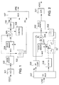
- FIG. 1 is a block diagram illustrating the first embodiment of an encoder according to the invention.
- the encoder comprises at its input an A/D converter 101, which converts an incoming video signal VIDEO into digital form. From the A/D converter the sampled video signal is applied to a data input D in an image memory 102, and digitized image information is stored in the image memory on an image-by-image basis. From the image memory the image is read onwards on a block-by-block basis.
- the encoder comprises a block memory 104 having a data input D to which the output of the image memory is connected.
- the output is further connected to an input in a processing unit performing the image block classification, such as a filter 103, and to one input in a summing circuit 105.
- the output of the block memory 104 is connected to another input in the summing circuit.
- the summing circuit calculates a difference value describing the correspondence between an image block to be transmitted and an image block acting as a prediction block candidate in a manner known per se , e.g. by calculating the sum of the absolute values of the differences between the intensity values of corresponding pixels (or the sum of the squared differences). This difference will be indicated by the reference ⁇ below, the (uncompressed) difference between the intensity values of corresponding pixels by the reference ⁇ p, and the last-mentioned compressed difference by the reference Ep.
- the output of the classification filter 103 is connected to an address input A in the block memory 104 and to a multiplexer 107 having its output connected to the line.
- the output of the summing circuit 105 is connected both to a compression circuit 106 and to a control circuit 108 controlling the operations of the encoder.
- the output of both of the two last-mentioned circuits is connected to the multiplexer 107, the output signal of which is applied to the line.
- the compression circuit 106 is not necessary for the encoder; it forms part of the preferred embodiment of the device, as will be seen below.
- the encoder operates in the following way.
- An image to be encoded is stored in the image memory 102, from which it is read block by block into the block memory 104.
- the value of the output signal of the block memory is zero, whereby all blocks of the first image are applied as such to the compression circuit 106, where they are compressed by a compression method known per se , such as the DCT (Discrete Cosine Transform), and then transmitted to the line via the multiplexer 107.
- a compression method known per se such as the DCT (Discrete Cosine Transform)
- the block memory 104 is initialized by displacing a block having n x m pixels on a pixel-by-pixel basis both horizontally and vertically, and the image content of each position (the intensity values of the pixels) is stored in the block memory 104 at an address FD derived from the image content of the concerned block by classifying filtration in the filter 103.
- the next image content data item to be stored at the same address is written over the preceding image content data item, so there is only one image content data item at a time at the same address.
- Classifying filtration means that an identifier (FD) is derived from the image content of the image block e.g. by filtering.
- the identifier classifies the image block unequivocally into a certain class, within which the image blocks differ only slightly from each other.
- the image content data at each address thus describes a large number of nearly identical blocks.
- the classification processing may consist e.g. of a combination of subsampling and truncation (subsampling means that some of the samples are disregarded, while truncation means that the number of bits used per one pixel is reduced).
- the coding of the image proceeds on a block-by-block basis in such a way that the output signal FD of the filter 103 acts as a read address for the block memory 104. If an acceptable prediction block is obtained from the output of the block memory (the difference value ⁇ obtained at the output of the summing circuit is small enough), the address data FD is transmitted to the line as well as, if considered necessary, the difference values ⁇ p, each one of which represents the difference between the intensity values of corresponding pixels in the image block to be transmitted and the prediction block.
- the comparison of the difference value ⁇ with a predetermined threshold value can be performed e.g. in the control unit 108. In place of direct address data it is also possible to transmit information about the way the address can be found e.g. in the address table of the receiver.
- the address data and the difference values may be compressed in a manner known per se .
- the block to be encoded is applied as such to the compression circuit 106, from which it is transmitted after compression in a known manner to the line (via the multiplexer).
- the block memory is thereby updated by storing the image content of the block in the block memory at a position indicated by the corresponding address data FD.
- the procedure is thereafter continued by coding the next block as described above. Initialization need not be repeated at the beginning of new images, as the image content of a block is stored in the block memory whenever no prediction block is found, and so the block memory is continuously updated.
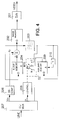
- Figure 2 shows a decoder according to the invention, where the same reference numerals as in Figure 1 have been used for the corresponding parts except that the numerals start with two (in accordance with the number of the figure).
- the decoder comprises at its input a demultiplexer 207 having a first output connected to a decompression circuit 206, a second output connected to a decoder control circuit 208, and a third output connected to an input terminal a in a switch S2.
- the control circuit 208 controls the operation of the switch S2.
- the outputs of the decompression circuit 206 and a block memory 204 are connected to respective inputs in a summing circuit 205 reconstructing the intensity values.
- the output of the summing circuit is connected to a data input D in the block memory, to a classification filter 203 (which is similar to the classification filter of the encoder), and to a data input D in an image memory.
- the output of the filter is connected to an input terminal c in the switch S2, and the output terminal of the switch is connected to an address input A in the block memory. From the image memory the image information is applied to a D/A converter 201 the output of which gives the original analog video signal VIDEO.
- the decoder receives the first image as such and releases possible compression in the decompression circuit 206.
- the output of the block memory 204 has the value zero.
- the block memory is initialized in the same way as in the transmitter (the switch is thereby in the position "c").
- the reception of a new image is then started. If the FD data has been sent from the transmitter, the switch S2 is in the position "a", whereby the FD address data acts as a read address for the block memory and indicates the address of the prediction block. If the receiver has indicated that the image block has been transmitted as such (or compressed in a known manner), it is assumed that the output of the block memory is zero. In this case, the image content of the image block is stored in the block memory 204 at an address obtained from the filter 203. The switch S2 is thereby in the position "c".
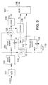
- Figure 3 illustrates the encoder according to the second embodiment of the invention.
- the encoder further comprises an auxiliary memory 109, which is used to predict an identifier FD for each block to be encoded.
- the output of the filter 103 is now connected to a data input D in the auxiliary memory 109, to an input in a delay unit 110 corresponding to the processing of one image block, to a first input terminal a in a switch S1, and to an input in a multiplexer 107.
- the output of the delay unit 110 is connected to an address input A in the auxiliary memory 109, and the output of the auxiliary memory is connected to a second input terminal b in the switch S1.
- the output terminal of the switch is connected to an address input A in the block memory 104.
- a control unit 108 controls the operation of the switch S1.
- the encoder shown in Figure 3 operates in the following way.
- An image to be encoded is stored in the image memory 102, from which it is read block by block into the block memory 104.
- the value of the output signal of the block memory is zero, whereby all blocks in the first image are applied as such to the compression unit 106 and then transmitted after compression in a known manner, such as by the DCT, to the line via the multiplexer 107.
- the block memory 104 is initialized by displacing a block having n x m pixels on a pixel-by-pixel basis both horizontally and vertically, and the image content of each position is stored in the block memory 104 at an address FD as described above.
- the switch S1 is thereby in the position "a".
- the auxiliary memory 109 is initialized such that each address FD derived in the filter 103 is stored, via the delay unit 110, at a memory position the address of which is the address FD corresponding to the preceding image block.
- the coding of the image proceeds on a block-by-block basis while the switch is initially in the position "b".
- the address FD derived from the preceding encoded image block is thereby used as read address data for the auxiliary memory 109, whereby a prediction value for the identifier of the block to encoded is obtained from the output of the auxiliary memory. If this prediction value, which is now used as a read address for the block memory 104, produces from the block memory a block such that the difference ⁇ between the intensity values of it and the block to be encoded is approximately zero, this image block is accepted as a prediction block and the control unit transmits a code RL via the multiplexer to the line.
- the code indicates the receiver that the prediction block can be found by the use of the preceding block.
- the code RL may be e.g. 1 bit.
- the pixel-specific difference values ⁇ p can, if considered necessary, be transmitted (compressed or as such) or left untransmitted. If the difference values are transmitted, the error will be eliminated totally in the receiver.
- the switch S1 is turned to the position "a", whereby the output signal of the filter 103 acts as a read address for the block memory 104. If an acceptable prediction block is now obtained from the output of the block memory (the obtained difference value ⁇ is small enough), the address data FD and possibly again the difference values ⁇ p are transmitted to the line.
- the value of the output signal of the block memory 104 is zero, whereby the block to be encoded is applied as such to the compression unit 106, and the block is transmitted to the line after having been compressed in a known manner.
- the image content of the block is thereby stored in the block memory 104 at a position indicated by the address FD, and the address FD is stored in the auxiliary memory 109 at a position indicated by the preceding address FD.
- the procedure is then continued by coding the next image block as described above.
- the embodiment shown in Figure 3 utilizes the correlation between the locations of successive prediction blocks.
- the RL code may be only 1 bit in length.
- FIG. 4 is a block diagram illustrating a decoder according to the second embodiment of the invention.
- the decoder further comprises, similarly as the encoder, an auxiliary memory 209 and a delay unit 210.
- the output of the auxiliary memory thus forms the input terminal b of the switch S2.
- the output of the filter is connected, similarly as in the encoder, to the data input of the auxiliary memory and to the address input A of the auxiliary memory via the delay unit 210 corresponding to the processing of one image block.
- the operation of the decoder corresponds to the operation of the decoder shown in Figure 2 except that in this case the received RL signal controls the switch S2 to the position "b", whereby the new block can be found from the block memory on the basis of the preceding block.
Landscapes
- Engineering & Computer Science (AREA)
- Multimedia (AREA)
- Signal Processing (AREA)
- Physics & Mathematics (AREA)
- General Physics & Mathematics (AREA)
- Theoretical Computer Science (AREA)
- Compression, Expansion, Code Conversion, And Decoders (AREA)
- Compression Or Coding Systems Of Tv Signals (AREA)
Applications Claiming Priority (2)
| Application Number | Priority Date | Filing Date | Title |
|---|---|---|---|
| FI933094 | 1993-07-05 | ||
| FI933094A FI94308C (fi) | 1993-07-05 | 1993-07-05 | Menetelmä ja laite digitaalisen videosignaalin kompressoimiseksi |
Publications (2)
| Publication Number | Publication Date |
|---|---|
| EP0633701A2 true EP0633701A2 (fr) | 1995-01-11 |
| EP0633701A3 EP0633701A3 (fr) | 1995-03-29 |
Family
ID=8538284
Family Applications (1)
| Application Number | Title | Priority Date | Filing Date |
|---|---|---|---|
| EP94110461A Withdrawn EP0633701A3 (fr) | 1993-07-05 | 1994-07-05 | Méthode et dispositif pour la compression d'un signal vidéo numérique. |
Country Status (2)
| Country | Link |
|---|---|
| EP (1) | EP0633701A3 (fr) |
| FI (1) | FI94308C (fr) |
Cited By (13)
| Publication number | Priority date | Publication date | Assignee | Title |
|---|---|---|---|---|
| WO1995020296A1 (fr) * | 1994-01-19 | 1995-07-27 | University Of Strathclyde | Compression fractale de donnees |
| EP0665692A2 (fr) * | 1994-01-31 | 1995-08-02 | Sony Corporation | Méthode et appareil de collation d'images |
| WO1996027986A1 (fr) * | 1995-03-07 | 1996-09-12 | Geoworks Limited | Procede de transmission de donnees et procede et appareil destines a afficher des donnees |
| WO1996027985A1 (fr) * | 1995-03-07 | 1996-09-12 | Geoworks Limited | Procede de transmission de donnees et procede et appareil destines a afficher des donnees |
| WO2001020894A2 (fr) * | 1999-09-15 | 2001-03-22 | Siemens Aktiengesellschaft | Procede et dispositif pour le traitement ou le traitement inverse d'au moins une partie d'une image, produits programmes d'ordinateur et support d'informations lisible par ordinateur |
| WO2001069938A1 (fr) * | 2000-03-15 | 2001-09-20 | Digital Accelerator Corporation | Codage d'image video numerique ayant un contenu eleve en mouvement |
| NL1031379C2 (nl) * | 2006-03-15 | 2007-09-18 | Ipo Paulus Willem Marinus Mari | Werkwijze en inrichting voor het coderen en decoderen van data. |
| EP2265029A1 (fr) * | 2009-06-17 | 2010-12-22 | Gurulogic Microsystems OY | Processeur d'images, générateur d'images et programme informatique |
| US8625665B2 (en) | 1996-09-20 | 2014-01-07 | At&T Intellectual Property Ii, L.P. | Video coder providing implicit coefficient prediction and scan adaptation for image coding and intra coding of video |
| US8630353B1 (en) | 2001-06-05 | 2014-01-14 | At&T Intellectual Property Ii. L.P. | Method and computer-readable medium for content adaptive video decoding |
| US9456208B2 (en) | 2001-06-05 | 2016-09-27 | At&T Intellectual Property Ii, L.P. | Method of content adaptive video encoding |
| US9602699B2 (en) | 2001-06-05 | 2017-03-21 | At&T Intellectual Property Ii, L.P. | System and method of filtering noise |
| US10341654B1 (en) | 2001-06-05 | 2019-07-02 | At&T Intellectual Property Ii, L.P. | Computing device for content adaptive video decoding |
Citations (1)
| Publication number | Priority date | Publication date | Assignee | Title |
|---|---|---|---|---|
| EP0534282A1 (fr) * | 1991-09-23 | 1993-03-31 | Oy Nokia Ab | Procédé de compression d'une image vidéo codé numeriquement |
-
1993
- 1993-07-05 FI FI933094A patent/FI94308C/fi active
-
1994
- 1994-07-05 EP EP94110461A patent/EP0633701A3/fr not_active Withdrawn
Patent Citations (1)
| Publication number | Priority date | Publication date | Assignee | Title |
|---|---|---|---|---|
| EP0534282A1 (fr) * | 1991-09-23 | 1993-03-31 | Oy Nokia Ab | Procédé de compression d'une image vidéo codé numeriquement |
Non-Patent Citations (6)
| Title |
|---|
| IEE PROCEEDINGS, vol.138, no.1, February 1991 pages 53 - 60, XP208143 S. PANCHANATHAN ET AL. 'Mini-max algorithm for image adaptive vector quantization' * |
| IEEE TRANSACTIONS ON COMMUNICATIONS, vol.36, no.8, August 1988 pages 957 - 971, XP52119 N. NASRABADI ET AL. 'Image coding using vector quantization : a review' * |
| IEEE TRANSACTIONS ON COMMUNICATIONS, vol.CO-34, no.7, July 1986, NEW YORK pages 703 - 710 M. GOLDBERG ET AL. 'Image sequence coding using vector quantization' * |
| IEEE TRANSACTIONS ON PATTERN ANALYSIS AND MACHINE INTELLIGENCE, vol.15, no.4, April 1993 pages 321 - 336, XP355504 Y. WANG ET AL. 'Image representation using block pattern models and its image processing applications' * |
| PROCEEDINGS OF 1990 IEEE INTERNATIONAL SYMPOSIUM ON CIRCUITS AND SYSTEMS, vol.2, May 1990 pages 1003 - 1006, XP166985 H. SUN ET AL. 'Motion-compensated vector quantization with a dynamic codebook' * |
| PROCEEDINGS OF EUSIPCO-92, vol.III, 24 August 1992 pages 1505 - 1508, XP356529 T. SAITO ET AL. 'Delayed-decision pattern-matching lossy image coding via copying' * |
Cited By (25)
| Publication number | Priority date | Publication date | Assignee | Title |
|---|---|---|---|---|
| WO1995020296A1 (fr) * | 1994-01-19 | 1995-07-27 | University Of Strathclyde | Compression fractale de donnees |
| EP0895426A3 (fr) * | 1994-01-31 | 1999-06-16 | Sony Corporation | Procédé et appareil pour l'estimation de mouvement avec correspondance de bloc |
| EP0665692A3 (fr) * | 1994-01-31 | 1996-04-03 | Sony Corp | Méthode et appareil de collation d'images. |
| EP0893924A2 (fr) * | 1994-01-31 | 1999-01-27 | Sony Corporation | Procédé et appareil d'évaluation de mouvement avec correspondance de bloc |
| EP0895423A2 (fr) * | 1994-01-31 | 1999-02-03 | Sony Corporation | Procédé et appareil pour l'estimation de mouvement avec correspondance de bloc |
| EP0895426A2 (fr) * | 1994-01-31 | 1999-02-03 | Sony Corporation | Procédé et appareil pour l'estimation de mouvement avec correspondance de bloc |
| EP0893924A3 (fr) * | 1994-01-31 | 1999-06-16 | Sony Corporation | Procédé et appareil d'évaluation de mouvement avec correspondance de bloc |
| EP0895423A3 (fr) * | 1994-01-31 | 1999-06-16 | Sony Corporation | Procédé et appareil pour l'estimation de mouvement avec correspondance de bloc |
| EP0665692A2 (fr) * | 1994-01-31 | 1995-08-02 | Sony Corporation | Méthode et appareil de collation d'images |
| WO1996027986A1 (fr) * | 1995-03-07 | 1996-09-12 | Geoworks Limited | Procede de transmission de donnees et procede et appareil destines a afficher des donnees |
| WO1996027985A1 (fr) * | 1995-03-07 | 1996-09-12 | Geoworks Limited | Procede de transmission de donnees et procede et appareil destines a afficher des donnees |
| US8625665B2 (en) | 1996-09-20 | 2014-01-07 | At&T Intellectual Property Ii, L.P. | Video coder providing implicit coefficient prediction and scan adaptation for image coding and intra coding of video |
| WO2001020894A2 (fr) * | 1999-09-15 | 2001-03-22 | Siemens Aktiengesellschaft | Procede et dispositif pour le traitement ou le traitement inverse d'au moins une partie d'une image, produits programmes d'ordinateur et support d'informations lisible par ordinateur |
| WO2001020894A3 (fr) * | 1999-09-15 | 2002-05-23 | Siemens Ag | Procede et dispositif pour le traitement ou le traitement inverse d'au moins une partie d'une image, produits programmes d'ordinateur et support d'informations lisible par ordinateur |
| WO2001069938A1 (fr) * | 2000-03-15 | 2001-09-20 | Digital Accelerator Corporation | Codage d'image video numerique ayant un contenu eleve en mouvement |
| US8630353B1 (en) | 2001-06-05 | 2014-01-14 | At&T Intellectual Property Ii. L.P. | Method and computer-readable medium for content adaptive video decoding |
| US9456208B2 (en) | 2001-06-05 | 2016-09-27 | At&T Intellectual Property Ii, L.P. | Method of content adaptive video encoding |
| US9602699B2 (en) | 2001-06-05 | 2017-03-21 | At&T Intellectual Property Ii, L.P. | System and method of filtering noise |
| US9866845B2 (en) | 2001-06-05 | 2018-01-09 | At&T Intellectual Property Ii, L.P. | Method of content adaptive video encoding |
| US9924201B2 (en) | 2001-06-05 | 2018-03-20 | At&T Intellectual Property Ii, L.P. | System and method of filtering noise |
| US10341654B1 (en) | 2001-06-05 | 2019-07-02 | At&T Intellectual Property Ii, L.P. | Computing device for content adaptive video decoding |
| WO2007105951A1 (fr) * | 2006-03-15 | 2007-09-20 | Van Den Boom Ipo Paulus Willem | Procédé et dispositif de codage et de décodage de données |
| NL1031379C2 (nl) * | 2006-03-15 | 2007-09-18 | Ipo Paulus Willem Marinus Mari | Werkwijze en inrichting voor het coderen en decoderen van data. |
| EP2265029A1 (fr) * | 2009-06-17 | 2010-12-22 | Gurulogic Microsystems OY | Processeur d'images, générateur d'images et programme informatique |
| US8649427B2 (en) | 2009-06-17 | 2014-02-11 | Gurulogic Microsystems Oy | Image processor, image generator and computer program |
Also Published As
| Publication number | Publication date |
|---|---|
| FI94308C (fi) | 1995-08-10 |
| EP0633701A3 (fr) | 1995-03-29 |
| FI933094A0 (fi) | 1993-07-05 |
| FI933094A (fi) | 1995-01-06 |
| FI94308B (fi) | 1995-04-28 |
Similar Documents
| Publication | Publication Date | Title |
|---|---|---|
| US4833535A (en) | Image transmission apparatus | |
| EP0385317B1 (fr) | Dispositif de traitement de signal | |
| EP0633701A2 (fr) | Méthode et dispositif pour la compression d'un signal vidéo numérique | |
| US4091424A (en) | Facsimile compression system | |
| US5021879A (en) | System for transmitting video pictures | |
| US4677479A (en) | System for re-quantization of coded picture signals | |
| US4597010A (en) | Video data transmission | |
| US5703966A (en) | Block selection using motion estimation error | |
| EP0637893A1 (fr) | Transcodeur | |
| EP0399487A2 (fr) | Dispositif de codage par transformation | |
| US5333137A (en) | Coding system having data controlling mechanism activated when error is detected | |
| WO1988008237A1 (fr) | Systeme dpcm a deux niveaux de resolution | |
| US5262878A (en) | Method and apparatus for compressing digital still picture signals | |
| EP0820195B1 (fr) | Codage d'images utilisant le sous-échantillonnage, la classification de blocs de pixels et l'association de coéfficients de conversion | |
| US6014171A (en) | Image encoding and decoding methods and apparatus utilizing the elimination of invalid code | |
| US5168374A (en) | Picture data encoding circuit with compression responsive to the amount of stored data | |
| JPS6316946B2 (fr) | ||
| KR100504415B1 (ko) | 화상부호화장치,화상부호화방법,화상복호장치,화상복호방법및기록매체 | |
| US5023715A (en) | Method of and apparatus for transmitting image information | |
| US7333542B1 (en) | Moving picture decoding apparatus and moving picture decoding method | |
| JPH04326669A (ja) | 画像符号化装置及び画像符号化方法 | |
| US6580758B1 (en) | Method of coding images at very low data rate and coding/decoding device implementing this method | |
| JPS5915438B2 (ja) | フレ−ム間符号化処理方式 | |
| JPH06217297A (ja) | 適応型dpcmコーダー | |
| USRE36680E (en) | Moving-image signal encoding apparatus with variably selected quantization step size |
Legal Events
| Date | Code | Title | Description |
|---|---|---|---|
| PUAI | Public reference made under article 153(3) epc to a published international application that has entered the european phase |
Free format text: ORIGINAL CODE: 0009012 |
|
| AK | Designated contracting states |
Kind code of ref document: A2 Designated state(s): DE ES FR GB IT NL SE |
|
| PUAL | Search report despatched |
Free format text: ORIGINAL CODE: 0009013 |
|
| AK | Designated contracting states |
Kind code of ref document: A3 Designated state(s): DE ES FR GB IT NL SE |
|
| 17P | Request for examination filed |
Effective date: 19950829 |
|
| 17Q | First examination report despatched |
Effective date: 19980814 |
|
| STAA | Information on the status of an ep patent application or granted ep patent |
Free format text: STATUS: THE APPLICATION IS DEEMED TO BE WITHDRAWN |
|
| 18D | Application deemed to be withdrawn |
Effective date: 20040203 |