EP0633548A2 - Verfahren und Gerät zum Nachweis eines Konturs in einem eine Dichteverteilung umfassenden Raum - Google Patents
Verfahren und Gerät zum Nachweis eines Konturs in einem eine Dichteverteilung umfassenden Raum Download PDFInfo
- Publication number
- EP0633548A2 EP0633548A2 EP94201787A EP94201787A EP0633548A2 EP 0633548 A2 EP0633548 A2 EP 0633548A2 EP 94201787 A EP94201787 A EP 94201787A EP 94201787 A EP94201787 A EP 94201787A EP 0633548 A2 EP0633548 A2 EP 0633548A2
- Authority
- EP
- European Patent Office
- Prior art keywords
- contour
- vertices
- vertex
- space
- energy
- Prior art date
- Legal status (The legal status is an assumption and is not a legal conclusion. Google has not performed a legal analysis and makes no representation as to the accuracy of the status listed.)
- Granted
Links
Images


Classifications
-
- G—PHYSICS
- G06—COMPUTING OR CALCULATING; COUNTING
- G06T—IMAGE DATA PROCESSING OR GENERATION, IN GENERAL
- G06T7/00—Image analysis
- G06T7/0002—Inspection of images, e.g. flaw detection
- G06T7/0012—Biomedical image inspection
-
- G—PHYSICS
- G06—COMPUTING OR CALCULATING; COUNTING
- G06T—IMAGE DATA PROCESSING OR GENERATION, IN GENERAL
- G06T7/00—Image analysis
- G06T7/10—Segmentation; Edge detection
- G06T7/12—Edge-based segmentation
-
- G—PHYSICS
- G06—COMPUTING OR CALCULATING; COUNTING
- G06T—IMAGE DATA PROCESSING OR GENERATION, IN GENERAL
- G06T2207/00—Indexing scheme for image analysis or image enhancement
- G06T2207/10—Image acquisition modality
- G06T2207/10132—Ultrasound image
-
- G—PHYSICS
- G06—COMPUTING OR CALCULATING; COUNTING
- G06T—IMAGE DATA PROCESSING OR GENERATION, IN GENERAL
- G06T2207/00—Indexing scheme for image analysis or image enhancement
- G06T2207/20—Special algorithmic details
- G06T2207/20092—Interactive image processing based on input by user
- G06T2207/20096—Interactive definition of curve of interest
-
- G—PHYSICS
- G06—COMPUTING OR CALCULATING; COUNTING
- G06T—IMAGE DATA PROCESSING OR GENERATION, IN GENERAL
- G06T2207/00—Indexing scheme for image analysis or image enhancement
- G06T2207/30—Subject of image; Context of image processing
- G06T2207/30004—Biomedical image processing
- G06T2207/30101—Blood vessel; Artery; Vein; Vascular
Definitions
- the invention relates to a method for determining a contour in a space with a density variation, comprising: defining a plurality of initial vertices being located on a seed contour, said vertices being connected by edges to neighbouring vertices; defining an energy function comprising an internal portion which is a function of the curvature at each of the vertices and an external portion determined by the density variation at the location of each of said vertices; determining a final contour by continuously varying the position of the vertices till the energy function reaches a minimum.
- Such a method can, for example, be used in a medical environment for (semi-)automatically defining the outline of a region of interest or of an object, such as an organ or a tumour, in a 2 or 3 dimensional image.
- Images of clinical importance can be obtained by a variety of modalities for example, a conventional X-ray technique, a CT-scanner, magnetic resonance imaging, single photon emission computerised tomography, positron emission tomography or by means of ultrasound echoscopy.
- Other areas in which deformable contours can be used are, for example, computer graphics and animation.
- the defined outline of the object can, for example, be used as a basis for providing quantitative information to a physician, for surface extraction for visualisation or for volume definition.
- the term energy function is not related to physical energy, but is used because the procedure of contour definition has some resemblance to a string of interconnected masses moving in a field of varying potential energy and trying to establish a stable situation of minimum energy.
- the external portion of the energy function corresponds to the density or potential energy and the internal portion to the mutual interaction of the elements of the string.
- Such a method for defining is known from an article by J.V. Miller et al ., entitled “Geometrically deformed models: A method for extracting closed geometric models from volume data", published in Computer Graphics, Vol. 25, No. 4, (1991), pages 217-226.
- a contour is described as a set of vertices connected by edges.
- the energy function comprises a topology preserving energy term, dependent on an estimation of local curvature and the distance between a vertex and its neighbours, an image event energy term, derived from the density (or pixel values), and a locally defined deformation potential driving the vertices outward or inward.
- the energy function is evaluated for the vertex positions, not for the trajectory of the connecting edges.
- the value of the energy function can decrease if a vertex is displaced along an edge and, therefore, the different vertices tend to cluster in comers of the contour.
- Another disadvantage is that the contour may collapse or expand within a region in which no density variation is present.
- the known method needs the topology preserving term in the energy function.
- This topology maintaining term provides constraints or interactions between vertices which are artificial and not related to the density variation in the space. Accordingly, deviations between the contour obtained and the actual shape of the object may occur due to these constraints.
- an object of the invention to provide a method for defining a contour in which method there is no interaction between vertices.
- the method according to the invention is characterised in that for each of the vertices the internal portion of the energy function is dependent on the angle between the edges at the respective vertex and in that the external portion of the energy function is related to the density variation in a direction having equal angles with each of the edges at the respective vertex.
- the energy contribution of each vertex to the contour as a whole does not depend on the distance to the neighbouring vertices and there is no direct interaction between the vertices.
- the energy variation at a vertex depends only on the direction "perpendicular" to the local path of the contour, during each iteration vertices will move only in this perpendicular direction and clustering of vertices will be avoided.
- the method according to the invention can be further characterised in that the internal energy portion is derived from the difference in angles of the edges at a series of adjacent vertices.
- the internal portion is made dependent on the shape of the contour.
- the internal portion will only contribute if the "curvature" of the contour, i.e . the numerical value of the angle between edges at adjacent vertices, changes.
- the internal portion of the energy function contributes in this way, in a region with no density variation a circular portion of the contour will not shrink, while a zigzag portion of the contour will straiten. Both kinds of behaviour represent a desired feature of the contour.
- An embodiment of this method is characterised in that said internal energy portion is obtained by the convolution of said difference in angles with a symmetric discrete filter having a zero frequency component equal to zero.
- a filter imposes the desired behaviour.
- the most simple form of such filter is (-1 ⁇ 2, 1, -1 ⁇ 2), i.e . the internal portion at a vertex is proportional to the angle at the vertex itself minus the average of the angles at both adjacent vertices.
- An embodiment of the method according to the invention is characterised in that the seed contour is open. In a two-dimensional situation this corresponds to a curve in the space having two ends. Such an end has only one edge and no energy contribution from a term that corresponds to the angle of two edges.
- a three-dimensional contour it means that a face between a number of vertices is, at least at one side, not joined by another face. In both cases vertices can move away from the contour, thereby extending the contour and eventually closing it.
- a preferred embodiment of the method according to the invention is characterised in that if during minimization of the energy function an edge length exceeds a first predetermined threshold, the edge is replaced by an additional vertex and connecting edges.
- edges become too short a computational load in performing the method is present without any benefit in resolution. In that case the short edge is taken out.
- An embodiment of the method is characterised in that a user defined energy distribution is added to the external portion of the energy function.
- a user function forces the contour to respect user defined restrictions, for example to keep out of areas in the space where the user knows no interesting features are present.
- contours have to be determined in a number of similar images, for example images representing adjacent slices in a body obtained by CT or MRI, it is possible to use the results in one slice as a starting point in the next.
- Such an embodiment of the method is characterised in that firstly a contour is determined in a first space and that, secondly, a contour is determined in a second space having a density variation having similar features to the density variation in the first space whereby the seed contour in the second space is defined by transfer of the final contour obtained in the first space.
- the invention also relates to an arrangement for determining a contour a space in which a given parameter has a value varying throughout said space, the arrangement comprising
- the dynamic contour actively modifies its shape, thus approximating some desired contour.
- the driving force behind the shape deformation is calculated from internal forces, derived from the shape of the contour itself, and an external force field, derived from some image feature energy distribution.
- the internal forces will try to minimize local contour curvature, while the external forces will try to make the contour follow a valley or a ridge through the 'landscape' formed by the image feature or density variation.
- the deformation process is performed in a number of discrete steps, after each of which the situation with regard to position, velocity and acceleration is evaluated for each of the vertices.
- internal and external forces on a vertex are calculated from the position of the vertex and its neighbours. These forces result in an acceleration, which changes the velocity of the vertex. This velocity determines the displacement of the vertex during the next deformation step.
- a stable end situation will be reached in which there is an equilibrium, which means that velocity and acceleration are zero for each vertex. Described in terms of energies, this situation represents a local minimum of the energy function.
- shrinking of closed contours owing to internal forces there are two undesirable effects which may occur: shrinking of closed contours owing to internal forces, and clustering or gathering of vertices in corners of the contour, owing to external forces.
- the shrinking problem is overcome by a proper definition of local curvature at the vertices, combined with a definition of internal forces which is derived from local curvature in such a way, that these forces are not only zero for parts of the contour where curvature is zero, but also for parts where the curvature is constant.
- the solution to the second problem is found by allowing only locally radial vertex displacements.
- Figure 1 presents the basic structure of the contour 10 as used in the invented method.
- the contour is an object consisting of vertices 11, 12, 13, ... which are connected by straight line segments or edges 14, 15, 16, ....
- the position of a vertex V i is represented by a vector p i and the edge between V i and V i+1 by a vector d i , the coordinate system is assumed to be Cartesian.
- Deformation is caused by a combination of forces which act on the vertices; the resulting acceleration in vertex V i is denoted by a vector a i .
- Another property of a vertex, not shown in the Figure, but important for the dynamic behaviour of the contour, is its velocity, denoted by v i for vertex V i .
- the length ⁇ d i ⁇ of an edge segment represents the local resolution of the contour: if it is large the contour will not be able to follow variations of small scale in the image feature energy distribution.
- the length ⁇ d i ⁇ may change during every deformation step, thus causing local variation in the resolution of the contour.
- the edge lengths are evaluated at regular intervals; where necessary, vertices are removed or inserted, thus keeping the resolution of the contour close to a user-specified scale.
- the energy function comprises an internal portion or, in other words, the vertices are subject to internal forces.
- the internal forces defined in the present method are related to the local curvature of the contour.
- the main objective of introducing internal forces or energy functions is illustrated in Figure 2: minimizing local curvature, forming a counterbalance to external forces that try to shape the contour according to all the variations of the image feature landscape, in order to obtain a good approximation of a smooth curve 20.
- the local curvature c i at V i is described by (see Figure 3): Defined in this way, local curvature has length (strength) as well as direction and provides a usable and unique measure for the angle between two joining edge segments. Moreover, the length of the curvature vector depends only on this angle, and is not influenced by the lengths of the two joining edge segments.
- locally radial and tangential directions at the position of a vertex are defined.
- the unit vectors representing the directions of the edge segments d i are defined.
- the locally tangential unit vector is defined as the normalized sum of the unit vectors of two joining edge segments (see Figure 4):
- the unit vector in the local radial direction is derived from by a rotation over ⁇ /2 radians.
- the vectors and now represent a local coordinate system at the position of vertex V i which is useful for the calculation of internal as well as external forces.
- the local curvature vector c i when described in terms of the local r,t -coordinate system is always directed along the local r -axis, pointing either in exactly the direction of , or in the opposite direction.
- c i is a vector along the local r -axis and its length can be described by the dot product ( c i ⁇ ).
- the length ⁇ c i ⁇ of the curvature vector can be positive as well as negative:
- Local curvature is defined now as a one-dimensional variable in locally radial direction.
- the internal forces which should act on the vertices of the contour are to be defined and restrictions put on the deformation process. In order to get a clear understanding of the contribution that internal forces will make to the deformation of the contour, a situation is considered in which external forces are completely absent.
- the shrinking process can be brought to a halt.
- This second constraint acts like an elastic force that keeps the distance between neighbouring vertices between certain limits. Vertices which are moving closer together will experience an increasingly repelling force that at some point will stop the shrinking process.
- the point where the shrinking process comes to a stop depends on the weights that are assigned to the two internal constraint forces. In other words: it is required to optimize the balance between the internal elastic force and the internal curvature minimizing force.
- Figures 5a, 5b and 5c illustrates on the left in Cartesian representations. besides the already discussed symmetric polygon 21 in Figure 5a, some typical shapes which may occur in a discrete contour.
- Figure 5b shows a portion 22 of a contour having a turn in direction over ⁇ radians and
- Figure 5c a portion 23 of a contour with alternating curvature direction. This further illustrates the inadequacy of using an internal force proportional to the curvature vector.
- the shape 22 in Figure 5b also shows a problem. It forms an extended part of a contour. If a force proportional to local curvature would be applied to the vertices, the extended part would become shorter as shown in the Figure. However, as with the shrinking of the shape in Figure 5a, this would not actually reduce local curvature, but only displace the curved region.
- the shape 23 shown in Figure 5c does not pose a problem; it is included because it represents a typical situation in which local curvature reduction may be required. Any solution to the shrinking problem should still perform well on this shape.
- the lengths of the internal force vectors should be zero for parts of the contour with constant curvature. Both conditions can be met if the sequence of dot products ( c i ⁇ ) along the contour is considered as a discrete scalar function, and if the convolution of this function with a discrete filter k i is used as the representation of the sequence of internal force vector lengths
- the first condition can be met by using as the direction of f in, i :
- the second condition is met by choosing appropriate filter coefficients for k i in which a convolution of a sequence of constant values with k i will be zero. This is achieved by a filter k i which is a symmetric discrete filter with a zero frequency component equal to zero.
- k i is a symmetric discrete filter with a zero frequency component equal to zero.
- Other possible filters provide an interesting way to optimize the behaviour of the contour for specific applications. In particular, in may be advantageous to make k i adaptive.
- an external potential energy distribution is assumed, which represents the energy or strength of some kind of image feature or combination of image features.
- image features For specific applications, the selection of appropriate image features for specific applications is an important subject but not part of the invention.
- simple image features like the pixel or voxel grayvalue itself and the length of the grayvalue gradient is demonstrated. If, for instance, a contour should follow a maximum gradient path through the image, the gradient length could be used as an image feature and an energy distribution defined that is high for large values of this feature. A maximum gradient path is then represented by a ridge in this energy distribution.
- the implementation of the deformation process is such that it will attempt to pull the vertices into local minima of the energy distribution, which is a natural behaviour.
- For the contour as a whole this means that it will end up following a path of low energy or a valley through the feature energy landscape. If the contour is to follow a ridge instead of a valley, as in this example, this can be done by inverting the energy distribution.
- the resulting distribution of potential energy is called E im .
- the elastic force is too strong it may obstruct the deformation process of the contour, because during deformation the vertices must have the freedom to move and change the distance to their neighbours. It follows that correct tuning is very important, but in general not possible.
- the internal elastic force cannot be tuned locally to the external forces f im, Vi and at the same time be tuned correctly to the internal forces f in, i .
- Vertex displacement along the path of the contour does not make any contribution to the deformation.
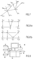
- Only the locally radial component of f im, Vi is used to drive the vertices of the contour. If the locally radial component f im, Vi is denoted by f im, r i , then its length is given by the dot product of f im, Vi and : This is illustrated in Figure 7, which shows the locally radial forces f im, r i and f in, i that provide a resulting driving force on the vertices of the contour which is purely devoted to deformation of the contour, without moving vertices along the path of the contour.
- the distance between a vertex and its neighbours determines the resolution of the contour, details of the external image feature energy distribution, which are small enough, may pass through the spaces between the vertices, without having a significant influence on the final shape of the contour. Because of the deformation of the contour, the vertex to vertex distance will change constantly. This may result in local variation as well as in global changes in the resolution of the contour. Both are undesirable, but slight local variation in the resolution is unavoidable, because a deformation process can only be possible if the vertices have the freedom to move with respect to their neighbours. For this reason, the variation is kept between certain limits, by periodically resampling the contour along its path. In local r,t -coordinates this translates into a resampling along the t -axis.
- the weighting factors w ex and w in may have default values for each application but allow modification by the operator.
- w damp w ex f ex, r i + w in f in, i + w damp v i .
- the weighting factor w damp is negative and determines the amount of damping. Even a small damping factor suffices to ensure stability of the deformation process.
- the actual deformation process is implemented as a so-called numerical time integration process, in which the complete state of the contour is calculated at a sequence of discrete positions in time.
- t describe the state of the contour at a certain point t in time
- t + ⁇ t the situation at a time ⁇ t later
- f i ( t + ⁇ t ) The value of f i ( t + ⁇ t ) is calculated as indicated hereinbefore.
- the value m i would, in a physical context, represent the 'mass' of vertex V i .
- no use is made of the possibility to assign different mass values to the vertices of the contour.
- m i reduces to a constant scaling factor.
- the procedure was further simplified by giving the time interval ⁇ t a value of one.
- An option which is available for open contours is a growing process that adds vertices to one or both of the open ends of the contour. By integrating this growing with the deformation of the contour an efficient tracking method is obtained. Vertices that are added are positioned by extrapolating in the direction of the last (or first) edge segment, which is at the same time continuously being repositioned by the deformation process. An automatic closing option can be added as well, such that both ends of an open contour are automatically connected when the distance between them becomes smaller than a certain threshold.
- l des the desired length for the edge segments of the contour.
- a default value for l des can be calculated by normalizing l des by the inner scale of the image. This means that l des increases when the image is considered at a coarser scale. From l des two other values l min and l max are derived, representing the minimum and maximum distance which is allowed between neighbouring vertices.
- resampling is implemented as a two pass process:
- the first pass checks along the entire contour if any segment length has become shorter than the minimum length l min . If such an edge segment is found, this edge segment is removed from the contour by replacing the two vertices on both ends of this segment by one single vertex at a position exactly in-between the replaced vertices. This is illustrated in Figure 8a, showing two closely adjacent vertices V i and V i+1 being replaced by a single vertex V j .
- the second pass checks again along the entire contour, but now for segments with a length larger than the maximum length l max . In this case such an edge segment is divided into two shorter ones of equal length, as illustrated in Figure 8b.
- a vertex V j+1 is inserted halfway in between vertices V i and V i+1 , necessarily the latter vertex is to be relabelled to V j+2 .
- the values of l min and l max are derived from the length l des . The relation between these parameters is constrained by not admitting an oscillatory behaviour, in which vertices are repeatedly removed in one resampling action and inserted again in the next. This leads to the requirement that l max > 2 l min . In the prototype implementation the l min was set at 1 ⁇ 2 l des and l max at 3 l min with satisfactory results.
- a prototype implementation of the described method was applied to clinical images, in particular to a typical clinical intravascular ultrasound image.
- the image represented a cross-section through a blood vessel, scanned by a full 2 ⁇ radians rotation of a transducer mounted on the tip of a catheter.
- Such an image comprises a number of more or less elliptical shapes, representing the layered structure of the vessel wall. Some of these elliptical shapes show up as bright ridges, while others show up as dark valleys. The area inside the vessel was partly blocked. The remaining open area was visible as a dark region. Both bright ridges and dark valleys are interesting from a clinical point of view, as well as the edge of the open area.
- the inverse pixel grayvalue was used as the image feature energy distribution, in order to allow the method to direct the contour to follow valleys.
- the pixel grayvalues themselves can be used.
- the contour to be defined along the edge of the open area inside the vessel it was chosen to position the desired path of this contour between dark and bright image regions, so to make it to follow a path of maximum grayvalue gradient.
- the contour in the used implementation of the method will follow valleys through the external image feature distribution, the reciprocal length of the grayvalue gradient is suitable as the image feature energy distribution. In such distribution, parts of the edge of the open area show up as valleys which do however not form a closed shape.
- the contour found by the method and the original image appeared to be an accurate definition of the edge of the open area.
- the operator-defined initial contour may have a very low resolution without jeopardizing the contour finding process.
- the initial resolution is automatically and quickly increased by the resampling mechanism, which is integrated in the deformation process, until it is on the level that was specified via the parameter l des . This will be realized after only a few deformation steps, and from there on the resampling process will keep the resolution at the required level. Consequently, the amount of user interaction in defining an initial contour can be very small. The amount of interaction may be reduced even further, by making use of the possibility to create an open contour as an initial contour, and letting it grow by finding its own path.
- contours have to be defined in more or less similar images
- operator intervention can be reduced by using the resulting contour of an image as the start contour for a next image. This occurs, for example, in MRI or CT images in which a volume of a patient is scanned and the results are presented as a plurality of two-dimensional images, each image representing a slice from the volume.
- a workstation 50 is sketched in which the present invention can be applied.
- the workstation 50 comprises a display screen 51 for displaying images, a memory 52 and computing means 53.
- the workstation further comprises an input device 54 for input of data that represent an image in which contours are to be determined.
- Such an input device is, for example a magnetic or optical disc reader or a magnetic tape reader. It may also be a link to a central data storage or to a device that generates image data, for example an ultrasound device, a CT-scanner or an MRI-apparatus.
- the workstation even can form an integral part of such device and allow the operator to determine contours in generated images and use the results obtained to determine which further image data should be taken.
- An operator console 55 for example a keyboard, is provided for the user to give commands to the workstation.
- a pointing device 56 for example a lightpen, a tracker ball or a "mouse" for pointing at specific locations to define a start contour may be present as well.
- Additional devices may be connected to the workstation, such as a unit 57 to provide a hard copy of the image visible on the display or a storage unit 58 for storing images and contour data obtained for later recall.
- the data are read from the input device 54 and are stored in memory 52.
- the data represent a parameter with a variation in a space in which contours are to be determined.
- the parameter data are normally given as a number of values, each value giving the parameter value as determined in a small element (pixel or voxel) of the space investigated.
Landscapes
- Engineering & Computer Science (AREA)
- Computer Vision & Pattern Recognition (AREA)
- Physics & Mathematics (AREA)
- General Physics & Mathematics (AREA)
- Theoretical Computer Science (AREA)
- Health & Medical Sciences (AREA)
- General Health & Medical Sciences (AREA)
- Medical Informatics (AREA)
- Nuclear Medicine, Radiotherapy & Molecular Imaging (AREA)
- Radiology & Medical Imaging (AREA)
- Quality & Reliability (AREA)
- Image Analysis (AREA)
Priority Applications (1)
| Application Number | Priority Date | Filing Date | Title |
|---|---|---|---|
| EP94201787A EP0633548B1 (de) | 1993-06-29 | 1994-06-22 | Verfahren und Gerät zur Bestimmung einer Kontur in einem durch eine Dichteverteilung gekennzeichneten Raum |
Applications Claiming Priority (3)
| Application Number | Priority Date | Filing Date | Title |
|---|---|---|---|
| EP93201882 | 1993-06-29 | ||
| EP93201882 | 1993-06-29 | ||
| EP94201787A EP0633548B1 (de) | 1993-06-29 | 1994-06-22 | Verfahren und Gerät zur Bestimmung einer Kontur in einem durch eine Dichteverteilung gekennzeichneten Raum |
Publications (3)
| Publication Number | Publication Date |
|---|---|
| EP0633548A2 true EP0633548A2 (de) | 1995-01-11 |
| EP0633548A3 EP0633548A3 (de) | 1995-04-19 |
| EP0633548B1 EP0633548B1 (de) | 2002-01-30 |
Family
ID=26133880
Family Applications (1)
| Application Number | Title | Priority Date | Filing Date |
|---|---|---|---|
| EP94201787A Expired - Lifetime EP0633548B1 (de) | 1993-06-29 | 1994-06-22 | Verfahren und Gerät zur Bestimmung einer Kontur in einem durch eine Dichteverteilung gekennzeichneten Raum |
Country Status (1)
| Country | Link |
|---|---|
| EP (1) | EP0633548B1 (de) |
Cited By (5)
| Publication number | Priority date | Publication date | Assignee | Title |
|---|---|---|---|---|
| EP0749097A1 (de) * | 1995-06-16 | 1996-12-18 | Alcatel | Verfahren zur Bestimmung von Kontouren durch gemischte Anwendung von Aktivkontur- und Verfolgungsarbeitsweise |
| WO1998045809A1 (en) * | 1997-04-04 | 1998-10-15 | Avid Technology, Inc. | Computer system process and user interface for providing intelligent scissors for image composition |
| EP1198200A4 (de) * | 1999-07-02 | 2004-06-23 | Cleveland Clinic Foundation | Intravaskuläre ultraschallanlage unter verwendung einer aktiven konturmethode und eines entsprechenden systems |
| US7359554B2 (en) | 2002-08-26 | 2008-04-15 | Cleveland Clinic Foundation | System and method for identifying a vascular border |
| CN108030510A (zh) * | 2017-11-20 | 2018-05-15 | 深圳蓝韵医学影像有限公司 | 膀胱容积测量方法、装置及计算机可读存储介质 |
Families Citing this family (1)
| Publication number | Priority date | Publication date | Assignee | Title |
|---|---|---|---|---|
| DE102005044405A1 (de) | 2005-09-16 | 2007-03-22 | Siemens Ag | Verfahren zur bildlichen Darstellung eines in ein Untersuchungsobjekt mindestens teilweise eingeführten, medizinischen Instruments |
-
1994
- 1994-06-22 EP EP94201787A patent/EP0633548B1/de not_active Expired - Lifetime
Non-Patent Citations (4)
| Title |
|---|
| COMPUTER VISION GRAPHICS AND IMAGE PROCESSING, vol.53, no.2, DULUTH, MA US pages 211 - 218, XP178753 LAURENT D. COHEN 'On active contour models and balloons' * |
| J.V. MILLER ET AL.: "Geometrically Deformed Models: A Method for Extracting Closed Geometric Models from Volumetric Data", COMPUTER GRAPHICS, ACM, 01. July 1991, vol. 25, no. 4, pages 217 to 226 * |
| PROCEEDINGS OF THE 12TH CANADIAN SYMPOSIUM ON REMOTE SENSING : AN ECONOMIC TOOL FOR THE NINETIES ,JULY 10-14 TH 1989 ,VANC OUVER, CANADA ;IEEE PRESS, NEW YORK (US) pages 1268 - 1272, XP139265 DOMINGO MIHOVILOVIC ET AL. 'Evaluation of an elastic curve technique for automatically finding the auroral oval from satellite images' * |
| PROCEEDINGS OF THE SECOND INTERNATIONAL CONFERENCE ON COMPUTER VISION ,DECEMBER 5-8 1988, TAMPA (US) ; IEEE COMPUTER SOCIETY PRESS, WASHINGTON (US) pages 95 - 99, XP79943 AMIR A. AMINI ET AL. 'Using Dynamic Programming for minimizing the energy of active contours in the presence of hard constraints' * |
Cited By (8)
| Publication number | Priority date | Publication date | Assignee | Title |
|---|---|---|---|---|
| EP0749097A1 (de) * | 1995-06-16 | 1996-12-18 | Alcatel | Verfahren zur Bestimmung von Kontouren durch gemischte Anwendung von Aktivkontur- und Verfolgungsarbeitsweise |
| FR2735598A1 (fr) * | 1995-06-16 | 1996-12-20 | Alsthom Cge Alcatel | Methode d'extraction de contours par une approche mixte contour actif et amorce/guidage |
| US5862245A (en) * | 1995-06-16 | 1999-01-19 | Alcatel Alsthom Compagnie Generale D'electricite | Method of extracting contours using a combined active contour and starter/guide approach |
| WO1998045809A1 (en) * | 1997-04-04 | 1998-10-15 | Avid Technology, Inc. | Computer system process and user interface for providing intelligent scissors for image composition |
| US5995115A (en) * | 1997-04-04 | 1999-11-30 | Avid Technology, Inc. | Computer system process and user interface for providing intelligent scissors for image composition |
| EP1198200A4 (de) * | 1999-07-02 | 2004-06-23 | Cleveland Clinic Foundation | Intravaskuläre ultraschallanlage unter verwendung einer aktiven konturmethode und eines entsprechenden systems |
| US7359554B2 (en) | 2002-08-26 | 2008-04-15 | Cleveland Clinic Foundation | System and method for identifying a vascular border |
| CN108030510A (zh) * | 2017-11-20 | 2018-05-15 | 深圳蓝韵医学影像有限公司 | 膀胱容积测量方法、装置及计算机可读存储介质 |
Also Published As
| Publication number | Publication date |
|---|---|
| EP0633548B1 (de) | 2002-01-30 |
| EP0633548A3 (de) | 1995-04-19 |
Similar Documents
| Publication | Publication Date | Title |
|---|---|---|
| US5559901A (en) | Method and device for determining a contour in a space of image parameter values | |
| Lobregt et al. | A discrete dynamic contour model | |
| Mikic et al. | Segmentation and tracking in echocardiographic sequences: Active contours guided by optical flow estimates | |
| McInemey et al. | Topology adaptive deformable surfaces for medical image volume segmentation | |
| McInerney et al. | Medical image segmentation using topologically adaptable surfaces | |
| US8031919B2 (en) | Computerised cortex boundary extraction from MR images | |
| Koss et al. | Abdominal organ segmentation using texture transforms and a hopfield neural network | |
| McInerney et al. | T-snakes: Topology adaptive snakes | |
| Rueckert et al. | Automatic tracking of the aorta in cardiovascular MR images using deformable models | |
| Suri et al. | Shape recovery algorithms using level sets in 2-D/3-D medical imagery: a state-of-the-art review | |
| Whitaker | Volumetric deformable models: Active blobs | |
| Heiberg et al. | Time resolved three-dimensional automated segmentation of the left ventricle | |
| JP4026901B2 (ja) | 心筋の心外膜境界を決定する方法及び装置 | |
| US7015907B2 (en) | Segmentation of 3D medical structures using robust ray propagation | |
| JPH0852127A (ja) | 対象の輪郭上に位置するキー点を自動的に検出するための画像処理方法及び装置 | |
| Makowski et al. | Two-phase active contour method for semiautomatic segmentation of the heart and blood vessels from MRI images for 3D visualization | |
| Bredno et al. | A general discrete contour model in two, three, and four dimensions for topology-adaptive multichannel segmentation | |
| EP0633548B1 (de) | Verfahren und Gerät zur Bestimmung einer Kontur in einem durch eine Dichteverteilung gekennzeichneten Raum | |
| US20070121778A1 (en) | Method and System For Spinal Cord Detection In Computed Tomography Volume Data | |
| Kalvin | Segmentation and surface-based modeling of objects in three-dimensional biomedical images | |
| Snel et al. | Deformable triangular surfaces using fast 1-D radial Lagrangian dynamics-segmentation of 3-D MR and CT images of the wrist | |
| Ecabert et al. | Towards automatic full heart segmentation in computed-tomography images | |
| Lotjonen | Segmentation of MR images using deformable models: Application to cardiac images | |
| Bredno et al. | General finite element model for segmentation in 2, 3, and 4 dimensions | |
| Macan et al. | Hybrid optical flow and segmentation technique for LV motion detection |
Legal Events
| Date | Code | Title | Description |
|---|---|---|---|
| PUAI | Public reference made under article 153(3) epc to a published international application that has entered the european phase |
Free format text: ORIGINAL CODE: 0009012 |
|
| AK | Designated contracting states |
Kind code of ref document: A2 Designated state(s): DE FR GB NL |
|
| PUAL | Search report despatched |
Free format text: ORIGINAL CODE: 0009013 |
|
| AK | Designated contracting states |
Kind code of ref document: A3 Designated state(s): DE FR GB NL |
|
| 17P | Request for examination filed |
Effective date: 19951019 |
|
| 17Q | First examination report despatched |
Effective date: 19990910 |
|
| GRAG | Despatch of communication of intention to grant |
Free format text: ORIGINAL CODE: EPIDOS AGRA |
|
| GRAG | Despatch of communication of intention to grant |
Free format text: ORIGINAL CODE: EPIDOS AGRA |
|
| GRAH | Despatch of communication of intention to grant a patent |
Free format text: ORIGINAL CODE: EPIDOS IGRA |
|
| GRAH | Despatch of communication of intention to grant a patent |
Free format text: ORIGINAL CODE: EPIDOS IGRA |
|
| GRAA | (expected) grant |
Free format text: ORIGINAL CODE: 0009210 |
|
| REG | Reference to a national code |
Ref country code: GB Ref legal event code: IF02 |
|
| AK | Designated contracting states |
Kind code of ref document: B1 Designated state(s): DE FR GB NL |
|
| PG25 | Lapsed in a contracting state [announced via postgrant information from national office to epo] |
Ref country code: NL Free format text: LAPSE BECAUSE OF FAILURE TO SUBMIT A TRANSLATION OF THE DESCRIPTION OR TO PAY THE FEE WITHIN THE PRESCRIBED TIME-LIMIT Effective date: 20020130 Ref country code: FR Free format text: LAPSE BECAUSE OF FAILURE TO SUBMIT A TRANSLATION OF THE DESCRIPTION OR TO PAY THE FEE WITHIN THE PRESCRIBED TIME-LIMIT Effective date: 20020130 |
|
| REF | Corresponds to: |
Ref document number: 69429743 Country of ref document: DE Date of ref document: 20020314 |
|
| NLV1 | Nl: lapsed or annulled due to failure to fulfill the requirements of art. 29p and 29m of the patents act | ||
| EN | Fr: translation not filed | ||
| REG | Reference to a national code |
Ref country code: GB Ref legal event code: 746 Effective date: 20021111 |
|
| PLBE | No opposition filed within time limit |
Free format text: ORIGINAL CODE: 0009261 |
|
| STAA | Information on the status of an ep patent application or granted ep patent |
Free format text: STATUS: NO OPPOSITION FILED WITHIN TIME LIMIT |
|
| 26N | No opposition filed | ||
| PGFP | Annual fee paid to national office [announced via postgrant information from national office to epo] |
Ref country code: DE Payment date: 20070813 Year of fee payment: 14 |
|
| PGFP | Annual fee paid to national office [announced via postgrant information from national office to epo] |
Ref country code: GB Payment date: 20070626 Year of fee payment: 14 |
|
| GBPC | Gb: european patent ceased through non-payment of renewal fee |
Effective date: 20080622 |
|
| PG25 | Lapsed in a contracting state [announced via postgrant information from national office to epo] |
Ref country code: DE Free format text: LAPSE BECAUSE OF NON-PAYMENT OF DUE FEES Effective date: 20090101 |
|
| PG25 | Lapsed in a contracting state [announced via postgrant information from national office to epo] |
Ref country code: GB Free format text: LAPSE BECAUSE OF NON-PAYMENT OF DUE FEES Effective date: 20080622 |