EP0633370B1 - Gewölbtes Profil mit seitlichen Rillen für abdeckbare Bedachung - Google Patents
Gewölbtes Profil mit seitlichen Rillen für abdeckbare Bedachung Download PDFInfo
- Publication number
- EP0633370B1 EP0633370B1 EP94490025A EP94490025A EP0633370B1 EP 0633370 B1 EP0633370 B1 EP 0633370B1 EP 94490025 A EP94490025 A EP 94490025A EP 94490025 A EP94490025 A EP 94490025A EP 0633370 B1 EP0633370 B1 EP 0633370B1
- Authority
- EP
- European Patent Office
- Prior art keywords
- profile
- central body
- profile according
- hollow bodies
- legs
- Prior art date
- Legal status (The legal status is an assumption and is not a legal conclusion. Google has not performed a legal analysis and makes no representation as to the accuracy of the status listed.)
- Expired - Lifetime
Links
Images

Classifications
-
- E—FIXED CONSTRUCTIONS
- E04—BUILDING
- E04B—GENERAL BUILDING CONSTRUCTIONS; WALLS, e.g. PARTITIONS; ROOFS; FLOORS; CEILINGS; INSULATION OR OTHER PROTECTION OF BUILDINGS
- E04B7/00—Roofs; Roof construction with regard to insulation
- E04B7/16—Roof structures with movable roof parts
- E04B7/166—Roof structures with movable roof parts characterised by a translation movement of the movable roof part, with or without additional movements
-
- E—FIXED CONSTRUCTIONS
- E04—BUILDING
- E04C—STRUCTURAL ELEMENTS; BUILDING MATERIALS
- E04C3/00—Structural elongated elements designed for load-supporting
- E04C3/38—Arched girders or portal frames
-
- E—FIXED CONSTRUCTIONS
- E04—BUILDING
- E04D—ROOF COVERINGS; SKY-LIGHTS; GUTTERS; ROOF-WORKING TOOLS
- E04D3/00—Roof covering by making use of flat or curved slabs or stiff sheets
- E04D3/02—Roof covering by making use of flat or curved slabs or stiff sheets of plane slabs, slates, or sheets, or in which the cross-section is unimportant
- E04D3/06—Roof covering by making use of flat or curved slabs or stiff sheets of plane slabs, slates, or sheets, or in which the cross-section is unimportant of glass or other translucent material; Fixing means therefor
-
- E—FIXED CONSTRUCTIONS
- E04—BUILDING
- E04H—BUILDINGS OR LIKE STRUCTURES FOR PARTICULAR PURPOSES; SWIMMING OR SPLASH BATHS OR POOLS; MASTS; FENCING; TENTS OR CANOPIES, IN GENERAL
- E04H3/00—Buildings or groups of buildings for public or similar purposes; Institutions, e.g. infirmaries or prisons
- E04H3/10—Buildings or groups of buildings for public or similar purposes; Institutions, e.g. infirmaries or prisons for meetings, entertainments, or sports
- E04H3/14—Gymnasiums; Other sporting buildings
- E04H3/16—Gymnasiums; Other sporting buildings for swimming
- E04H3/165—Gymnasiums; Other sporting buildings for swimming having movable parts
-
- E—FIXED CONSTRUCTIONS
- E04—BUILDING
- E04D—ROOF COVERINGS; SKY-LIGHTS; GUTTERS; ROOF-WORKING TOOLS
- E04D3/00—Roof covering by making use of flat or curved slabs or stiff sheets
- E04D3/02—Roof covering by making use of flat or curved slabs or stiff sheets of plane slabs, slates, or sheets, or in which the cross-section is unimportant
- E04D3/06—Roof covering by making use of flat or curved slabs or stiff sheets of plane slabs, slates, or sheets, or in which the cross-section is unimportant of glass or other translucent material; Fixing means therefor
- E04D3/08—Roof covering by making use of flat or curved slabs or stiff sheets of plane slabs, slates, or sheets, or in which the cross-section is unimportant of glass or other translucent material; Fixing means therefor with metal glazing bars
- E04D2003/0806—Roof covering by making use of flat or curved slabs or stiff sheets of plane slabs, slates, or sheets, or in which the cross-section is unimportant of glass or other translucent material; Fixing means therefor with metal glazing bars the supporting section of the glazing bar consisting of one single extruded or rolled metal part
-
- E—FIXED CONSTRUCTIONS
- E04—BUILDING
- E04D—ROOF COVERINGS; SKY-LIGHTS; GUTTERS; ROOF-WORKING TOOLS
- E04D3/00—Roof covering by making use of flat or curved slabs or stiff sheets
- E04D3/02—Roof covering by making use of flat or curved slabs or stiff sheets of plane slabs, slates, or sheets, or in which the cross-section is unimportant
- E04D3/06—Roof covering by making use of flat or curved slabs or stiff sheets of plane slabs, slates, or sheets, or in which the cross-section is unimportant of glass or other translucent material; Fixing means therefor
- E04D3/08—Roof covering by making use of flat or curved slabs or stiff sheets of plane slabs, slates, or sheets, or in which the cross-section is unimportant of glass or other translucent material; Fixing means therefor with metal glazing bars
- E04D2003/0887—Glazing bars for coverings consisting of more than one sheet or glass pane
Definitions
- the present invention relates to discoverable cover structures, that is to say in which the panels forming the cover can slide relative to each other. They relate more particularly to a profile, suitable for such structures, which has superimposed lateral grooves for positioning the cover plates and their sliding.
- the present invention applies in particular to the field of sunroof swimming pools and light constructions of this type, some of the structural elements of which are arched arches forming arches.
- FR. A. 2,599,118 a profile specially adapted for the manufacture of shelter frames, in particular for covering swimming pools or greenhouses. It is a tubular profile, with a stiffening core and a peripheral wall of generally rounded shape, which is provided with lines of least resistance so as to delimit cutable strips which, once removed, define rebates for the passage of the cover plates.
- the stiffening core is a hollow body of rectangular section.
- Document FR.A.2.627.530 discloses a profile intended for the constitution of arches for a discoverable cover structure. This is a curved tubular profile consisting of a central support body, which carries, on each side and perpendicular to its central support body and the vertical axis of symmetry of the profile, lateral fins which are arranged one above the others and which delimit the lateral sliding grooves of the cover plates.
- the aim that the applicant has set for himself is to propose a profile of the type described in document FR.A.2.627.530, in that it comprises a central load-bearing body and several superposed sets of two symmetrical lateral fins, one on the other relative to the central support body, and forming a groove for a cover plate, but which overcomes the aforementioned drawbacks.
- the profile in its basic version with four sets of two fins only comprises on either side of the central carrying body two superposed grooves, each groove being delimited by an outer face of a lateral hollow body and the wing facing him.
- the twist resistance of the profile is given to it by the solid body.
- the hollow bodies improve the stiffening of the entire profile.
- the lower groove of the profile consisting of the recess between the two legs of the lower split part of the central body, allows the placement of vertical panels closing the ends of the structure.
- the lower groove of the profile serves as a housing for a fixing screw passing through the upper part of the solid body and said spacer; in this case, the profile preferably comprises a closing part, making it possible to close the lower groove, so as to return this fixing screw invisible.
- the split lower part of the full body has substantially the same height as the upper part. This provides greater reliability during bending.
- each hollow body is parallel to the vertical plane of symmetry of the profile and is substantially in alignment with the free ends of the other fins.
- the cross section of the groove between the two legs is of rectangular section.
- the hollow bodies preferably have an internal cross section in the form of an inverted cradle.
- At least the two fins forming the lower face of the hollow bodies have over their entire length, a groove capable of serving as a housing for a seal.
- This joint attenuates the vibrations of the cover plates which are mounted in the lower grooves formed by the two sets of fins superimposed on the lower part of the profile.
- the upper edge of the central body projects from the plane of the two fins of the upper clearance of the upper part of the profile. This edge provides a better seal when assembling two superimposed profiles.
- the transverse groove between the two legs of the upper profile being provided with a sealing flap, the upper edge of the central body of the lower profile comes to cooperate with said flap to ensure better sealing of the assembly.
- the profile of the invention is intended to constitute an arch for a discoverable cover structure.
- Figure 1 shows the different elements of a first particular embodiment of this profile, which appear clearly in cross section.
- the profile 1 has a solid carrying body 2, in two parts: an upper part and a lower part, in consideration of the median plane BB 'perpendicular to the vertical plane AA' of symmetry of the profile.
- the solid body is a plate having a thickness E , placed along the plane of symmetry AA '.
- the plate 3 is divided into two branches 4 and 5 which move away from the plane AA', then continue vertically in the lower part in two legs 6,7 parallel and symmetrical with respect to the plane AA '. These two legs have a thickness e , substantially half of E , and delimit a vertical groove 8.
- the profile 1 also comprises four superimposed sets 9, 10, 11, 12 of two fins arranged on either side of the solid carrying body 2, and symmetrical to one another with respect to the plane AA '.
- the set 9 made up of the fins 9a and 9b and the set 10 made up of the fins 10a and 10b are situated at the level of the plate 3 in the upper part of the carrier body 2.
- the set 11 made up of the two fins 11a and 11b and the set 12 made up of the two fins 12a and 12b are located at the level of the two legs 6 and 7 of the lower part of the carrier body 2.
- the two superimposed median fins 10a, 11a meet at a junction face 13a which is, in the example illustrated, parallel to the plane of symmetry AA 'and substantially in alignment with the two free ends 9' a and 12 ' at two other fins 9a, 12a.
- the two median fins 10a, 11a, the corresponding junction face 13a and the part of the carrier body 2 located between the two median fins 10a, 11a form a hollow lateral body 14a.
- This hollow body 14a has an interior cross section of substantially rectangular shape, except for the concavity corresponding to the step along the branch 5 in the median plane BB 'and the leg 7.
- the two superimposed median fins 10b, 11b, the corresponding junction face 13b and the part of the carrier body 2 located between the two median fins 10b and 11b form a hollow lateral body 14b.
- the thickness E of the solid plate 3 was 5 mm, that of 6.7 e 2 jambs, 5 mm; the distance d between the two legs 6.7 was 20 mm; the total height H of the section 1 was 100 mm, the plane BB 'being just median.
- the fins 9a, 9b, 10a, 10b of the upper part have a surface greater than those 11a, 11b , 12a, 12b of the lower part.
- the profile 1 is previously bent to give it the appropriate curvature, knowing that generally an arch is formed by the assembly of two curved profiles each forming a half-arch.
- two assembly sleeves are used which are placed inside the two hollow bodies 14a and 14b of the two profiles to be assembled, so that they are positioned astride the two profiles.
- the arches can be of various shapes, and in particular have the shape of a half-ellipse, the major axis of which would be coincident with the vertical axis of symmetry of the arch. In this case, a height gain is obtained compared to an arch having the shape of a semicircle.
- the lateral hollow bodies 14a and 14b have several functions: a function of assembly, as described above, of several profiles to form a unitary arch, a function of fixing to the ground, in which the hollow bodies are fitted on a fixing piece to the ground and fixed thereto by screws passing through the junction face opposite said ground fixing part. They also have an important role in the mechanical resistance of the profile, providing the full load-bearing body with additional stiffening.
- each hoop is fixed and kept at a distance from the or two hoops which are adjacent to it, using a spacer passing through the two hollow bodies of the profile.
- the fixing of the arch on the spacer can advantageously be carried out using a single fixing screw (not shown) which passes through the upper part of the solid body 2 and said spacer, and which is located in the lower groove 8, corresponding obviously to the two spans 6, 7.
- the interior of the groove 8, and by the same the fixing screw is visible from the inside of the structure formed by the arches .
- the profile of the invention preferably comprises a closing piece 18, making it possible to close the groove 8. This closing piece, which is for example snap-on, makes it possible to give a decorative finish to the profile .
- the groove 8 can also serve as housing either for the vertical panel closing the end of the structure or for a rubber sealing flap in the case of two superimposed arches.
- This latter scenario can occur in particular when the structure is of the telescopic type, that is to say when a first set composed of two arches supporting cover plates can move relative to a second set of arches and of plates, longitudinally relative to the general direction of the structure, and come to be embedded under this second set.
- the rubber flap held in the groove 8 of the profiles of the second set, descends to the level of the first set and provides the seal.
- the upper edge 3a of the plate 3 forming the upper part of the central supporting body 2 of the profile of the invention projects relative to the plane of the two upper fins 9a and 9b. In this way, the upper edge of the first set cooperates with the rubber flap which is held in the groove 8 of the profiles of the second set, in order to improve the seal.
- the ends 6 a , 7 has legs 6, 7 of the profile 1 are advantageously slightly curved towards the inside of the groove 8, so as to ensure a certain blocking of the rubber flap, and to prevent it from coming out groove 8 during possible friction against the first set.
- the presence of the groove 8 has an important advantage, when bending the profile 1: since it is located in the lower part of the profile, facing the inside of the arch and along the axis of symmetry of the profile , it turns out that the bending has a very high reliability.
- the profile 1 as just described comprises on the one hand two grooves 15a and 15b symmetrical to one another with respect to the axis AA ', and delimited by the two upper fins 9a and 9b and the two fins 10a and 10b forming the upper face of the hollow bodies 14a and 14b, and on the other hand two lower grooves 16a and 16b also symmetrical to each other with respect to the plane AA ', and delimited by the two fins lower 12a and 12b, and by the two fins 11a and 11b forming the underside of the hollow bodies 14a and 14b.
- Profile 1 can therefore receive four cover plates, generally made of transparent plastic, on the basis of one cover plate per groove.
- the cover plates inserted in the two upper grooves 15a, 15b and those inserted in the two lower grooves 16a and 16b are mounted sliding.
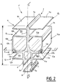
- FIG. 2 shows a profile 1 'which illustrates a second particular embodiment of the profile of the invention.
- the elements common to the two sections 1 and 1 ′ of FIGS. 1 and 2 have the same references.
- This profile 1 ′ differs essentially from profile 1 in that on the one hand the hollow bodies 14a and 14b have an interior cross section in the form of an inverted cradle, and on the other hand that the height of the groove 8 formed by the two legs 6 and 7 is less than half the height H of the profile.
- the profile has an upper part and a lower part, which are delimited by the plane CC ', and which are not equal.
- the thickness of the legs 6 and 7 is substantially equal to the thickness of the solid plate 3.
- the inverted cradle shape of the hollow bodies 14a and 14b makes it possible to increase the mechanical resistance of the profile.
- the Applicant has noticed that the plates which were slidably mounted inside the two lower grooves 16a and 16b of the section 1 of FIG. 1 tended to easily enter into vibration, causing parasitic noise at the level of the section.
- the fins 11a and 11b forming the lower face of the hollow bodies 14a and 14b are provided respectively with a groove 17a and 17b making the entire length of the hollow body, and intended to receive a seal.
- the purpose of this seal is to dampen any vibrations of the plates mounted in the lower grooves 16a and 16b of the profile 1 '.
- a felt seal is used.
- profile 1 ′ the additional material is advantageously used in the lower corners of the hollow bodies 14a and 14b, which is due to the inverted cradle shape of the internal cross section of these hollow bodies, to make the grooves 17a and 17b.
- the invention is not limited to the two embodiments which have been described by way of non-exhaustive examples.
Claims (8)
- Profil für abnehmbare Bedachungen, das einen zentralen Tragkörper und mehrere übereinander angeordnete Paare von seitlichen Rippen, die bezogen auf den zentralen Tragkörper symmetrisch zueinander sind, aufweist,
dadurch gekennzeichnet, daß der zentrale Tragkörper ein Vollkörper (2) ist, der in seinem unteren Teil in Form einer Gabel gedoppelt ist, deren beide Schenkel (6, 7) bezogen auf die Ebene (AA'), die durch den oberen Teil des genannten Vollkörpers verläuft, symmetrisch sind, und daß es aufweist:a) mindestens vier übereinander angeordnete Rippenpaare. zwei (9, 10) davon in Höhe des oberen Teils und zwei (11, 12) in Höhe des gedoppelten unteren Teils des zentralen Körpers,b) zwei seitliche Hohlkörper (14a, 14b) in einem Stück mit dem zentralen Körper, wobei jeder jeweils von den zwei übereinander angeordneten Rippen (10a bzw. 11a) der beiden mittleren Paare (10, 11) und einer Verbindungsseite (13a), die die Enden der beiden genannten Rippen verbindet, gebildet wird. - Profil nach Anspruch 1, das als Bogen für eine abnehmbare Bedachung verwendet wird,
dadurch gekennzeichnet, daß es an einer Querstrebe, die durch die beiden seitlichen Hohlkörper (14a, 14b) verläuft, mittels einer Befestigungsschraube befestigt ist, die in der unteren Auskehlung (8) des Profils sitzt, die der Aussparung zwischen den beiden Schenkeln (6, 7) entspricht und die sich durch den oberen Teil des Vollkörpers (2) erstreckt, und daß es ferner ein Verschlußstück (18) aufweist, mit dem die genannte Auskehlung (8) verschlossen werden kann. - Profil nach Anspruch 1,
dadurch gekennzeichnet, daß der gedoppelte untere Teil des Vollkörpers im wesentlichen die gleiche Höhe hat wie der obere Teil. - Profil nach Anspruch 1,
dadurch gekennzeichnet, daß die Verbindungsseite (13a, 13b) jedes Hohlkörpers (14a, 14b) parallel zu der senkrechten Symmetrieebene (AA') des Profils (1) verläuft und sich im wesentlichen auf der Fluchtlinie der freien Enden (9' a 12' a) der anderen Rippen (9, 12) befindet. - Profil nach Anspruch 1,
dadurch gekennzeichnet, daß der Querschnitt der Auskehlung (8) zwischen den beiden Schenkeln (6, 7) ein rechtwinkeliger Querschnitt ist. - Profil nach Anspruch 1,
dadurch gekennzeichnet, daß jeder Hohlkörper (14a, 14b) einen Innenquerschnitt in Form eines umgekehrten Sattels hat. - Profil nach Anspruch 1,
dadurch gekennzeichnet, daß die obere Kante (3a) des zentralen Tragkörpers über die Ebene der beiden Rippen (9a, 9b) des oberen Paares des oberen Profilteils hinausragt. - Profil nach Anspruch 1 oder 6,
dadurch gekennzeichnet, daß zumindest die Rippen (11a, 11b), die die Unterseite der Hohlkörper (14a bzw. 14b) bilden jeweils über die gesamte Länge des Hohlkörpers mit einer Rille (17a bzw. 17b) versehen sind, die als Aufnahme für eine Dichtung dienen kann.
Applications Claiming Priority (2)
| Application Number | Priority Date | Filing Date | Title |
|---|---|---|---|
| FR9306337 | 1993-05-21 | ||
| FR9306337A FR2705380A1 (fr) | 1993-05-21 | 1993-05-21 | Profile cintré à rainures latérales pour structure de couverture découvrable. |
Publications (2)
| Publication Number | Publication Date |
|---|---|
| EP0633370A1 EP0633370A1 (de) | 1995-01-11 |
| EP0633370B1 true EP0633370B1 (de) | 1995-10-11 |
Family
ID=9447497
Family Applications (1)
| Application Number | Title | Priority Date | Filing Date |
|---|---|---|---|
| EP94490025A Expired - Lifetime EP0633370B1 (de) | 1993-05-21 | 1994-05-20 | Gewölbtes Profil mit seitlichen Rillen für abdeckbare Bedachung |
Country Status (5)
| Country | Link |
|---|---|
| EP (1) | EP0633370B1 (de) |
| AT (1) | ATE129043T1 (de) |
| DE (1) | DE69400028T2 (de) |
| ES (1) | ES2081229T3 (de) |
| FR (1) | FR2705380A1 (de) |
Cited By (1)
| Publication number | Priority date | Publication date | Assignee | Title |
|---|---|---|---|---|
| WO2020105038A1 (en) * | 2018-11-19 | 2020-05-28 | Palram Industries (1990) Ltd. | Reinforced transparent roofing element |
Families Citing this family (3)
| Publication number | Priority date | Publication date | Assignee | Title |
|---|---|---|---|---|
| FR2784405A1 (fr) * | 1998-10-08 | 2000-04-14 | Jacques Sarrat | Profil porteur, multi-tubulaire, cintre, a rainures laterales, pour structures fixes ou mobiles |
| FR2821635B1 (fr) * | 2001-03-02 | 2006-04-07 | Rene Michel Verschuere | Profile cintre a barrette amovible pour structure de couverture decouvrable |
| FR2881160B1 (fr) * | 2005-01-25 | 2008-09-12 | Gerard Derhore | Structure de protection, notamment destinee a abriter un espace, une construction, telle que par exemple une piscine |
Family Cites Families (4)
| Publication number | Priority date | Publication date | Assignee | Title |
|---|---|---|---|---|
| GB1127011A (en) * | 1964-08-11 | 1968-09-11 | Clear Span Ltd | Improvements in or relating to buildings |
| FR2589500B1 (fr) * | 1985-11-06 | 1988-01-08 | Leurent Ghislain | Structure de couverture decouvrable d'un endroit quelconque, notamment d'une piscine |
| FR2599118B1 (fr) * | 1986-05-22 | 1988-09-09 | Formes Alu | Nouveau profile en vue de la fabrication d'ossature d'abris, notamment pour couverture de piscines, serres... et abris realises au moyen de ce profile |
| FR2627530B1 (fr) * | 1988-02-18 | 1993-10-15 | Leurent Ghislain | Profile cintre tubulaire a rainures laterales destine a la constitution d'arceaux pour structure de couverture decouvrable |
-
1993
- 1993-05-21 FR FR9306337A patent/FR2705380A1/fr active Pending
-
1994
- 1994-05-20 EP EP94490025A patent/EP0633370B1/de not_active Expired - Lifetime
- 1994-05-20 AT AT94490025T patent/ATE129043T1/de not_active IP Right Cessation
- 1994-05-20 DE DE69400028T patent/DE69400028T2/de not_active Expired - Lifetime
- 1994-05-20 ES ES94490025T patent/ES2081229T3/es not_active Expired - Lifetime
Cited By (1)
| Publication number | Priority date | Publication date | Assignee | Title |
|---|---|---|---|---|
| WO2020105038A1 (en) * | 2018-11-19 | 2020-05-28 | Palram Industries (1990) Ltd. | Reinforced transparent roofing element |
Also Published As
| Publication number | Publication date |
|---|---|
| DE69400028T2 (de) | 1996-03-21 |
| ATE129043T1 (de) | 1995-10-15 |
| ES2081229T3 (es) | 1996-02-16 |
| EP0633370A1 (de) | 1995-01-11 |
| DE69400028D1 (de) | 1995-11-16 |
| FR2705380A1 (fr) | 1994-11-25 |
Similar Documents
| Publication | Publication Date | Title |
|---|---|---|
| CA2437211A1 (fr) | Piscine hors-sol a structure rigide | |
| CA1277347C (fr) | Ski | |
| WO2002029182A1 (fr) | Profile pour structure de couverture notamment pour piscine | |
| EP0186217B1 (de) | Rahmen | |
| EP0633370B1 (de) | Gewölbtes Profil mit seitlichen Rillen für abdeckbare Bedachung | |
| EP0774032A1 (de) | Variabel gestaltete treppe | |
| EP3669037B1 (de) | Vorrichtung zur herstellung eines verstärkten schwimmbeckens | |
| FR2803365A1 (fr) | Profile metallique, en particulier pour du mobilier urbain | |
| EP0455554A1 (de) | Modulare Platte zur Überdeckung, insbesondere von Decken | |
| FR2714803A1 (fr) | Etagère à piliers rigidifiants. | |
| FR2711699A1 (fr) | Dispositif d'immobilisation d'un raidisseur vertical pour garde-corps vis-à-vis d'un support d'appui au sol. | |
| FR2557915A1 (fr) | Volet perfectionne destine a faire office de persienne a lames orientables | |
| EP1239099B1 (de) | Dachkonstruktion mit gebogenen Profilen und abnehmbaren Latten und ein Zubehör | |
| FR2624900A3 (fr) | Profile pour construction tridimensionnelle et construction telle que serre faisant application de profiles de ce type | |
| FR2672918A1 (fr) | Element d'encadrement de plaque; notamment pour la realisation de parois de batiment. | |
| CA2502508A1 (fr) | Piscine hors sol a paroi rigide avec margelle | |
| FR2776048A1 (fr) | Profile pour menuiserie du type coulissante | |
| FR3138463A1 (fr) | Clôture à lames avec entretoisement amélioré | |
| EP0133838A2 (de) | Rahmen für die Herstellung von Türen, Fenstern, Wänden und dergleichen | |
| BE1006113A3 (fr) | Mur assemble. | |
| FR2816340A1 (fr) | Dispositif d'assemblage de profiles de structure de toiture, en particulier de verriere, a multiple degres de liberte de position | |
| FR2770867A1 (fr) | Barriere a armature porteuse integree et portail en faisant application | |
| EP1640528B1 (de) | Trägerplatte für den Eckpfosten eines Geländers | |
| FR2479888A1 (fr) | Fenetre ou porte coulissante | |
| FR2770595A1 (fr) | Element d'assemblage angulaire et ensemble de boites aux lettres comprenant au moins un tel element |
Legal Events
| Date | Code | Title | Description |
|---|---|---|---|
| PUAI | Public reference made under article 153(3) epc to a published international application that has entered the european phase |
Free format text: ORIGINAL CODE: 0009012 |
|
| AK | Designated contracting states |
Kind code of ref document: A1 Designated state(s): AT BE CH DE DK ES FR GB GR IE IT LI LU MC NL PT SE |
|
| 17P | Request for examination filed |
Effective date: 19950102 |
|
| 17Q | First examination report despatched |
Effective date: 19950321 |
|
| GRAA | (expected) grant |
Free format text: ORIGINAL CODE: 0009210 |
|
| AK | Designated contracting states |
Kind code of ref document: B1 Designated state(s): AT BE CH DE DK ES FR GB GR IE IT LI LU MC NL PT SE |
|
| PG25 | Lapsed in a contracting state [announced via postgrant information from national office to epo] |
Ref country code: MC Free format text: LAPSE BECAUSE OF NON-PAYMENT OF DUE FEES Effective date: 19951011 Ref country code: GR Free format text: LAPSE BECAUSE OF FAILURE TO SUBMIT A TRANSLATION OF THE DESCRIPTION OR TO PAY THE FEE WITHIN THE PRESCRIBED TIME-LIMIT Effective date: 19951011 Ref country code: DK Effective date: 19951011 Ref country code: AT Effective date: 19951011 |
|
| REF | Corresponds to: |
Ref document number: 129043 Country of ref document: AT Date of ref document: 19951015 Kind code of ref document: T |
|
| ITF | It: translation for a ep patent filed |
Owner name: MARCHI & MITTLER S.R.L. |
|
| GBT | Gb: translation of ep patent filed (gb section 77(6)(a)/1977) |
Effective date: 19951010 |
|
| REG | Reference to a national code |
Ref country code: IE Ref legal event code: FG4D Free format text: 65706 |
|
| REF | Corresponds to: |
Ref document number: 69400028 Country of ref document: DE Date of ref document: 19951116 |
|
| PG25 | Lapsed in a contracting state [announced via postgrant information from national office to epo] |
Ref country code: SE Effective date: 19960111 Ref country code: PT Effective date: 19960111 |
|
| REG | Reference to a national code |
Ref country code: ES Ref legal event code: FG2A Ref document number: 2081229 Country of ref document: ES Kind code of ref document: T3 |
|
| PG25 | Lapsed in a contracting state [announced via postgrant information from national office to epo] |
Ref country code: IE Free format text: LAPSE BECAUSE OF NON-PAYMENT OF DUE FEES Effective date: 19960426 |
|
| REG | Reference to a national code |
Ref country code: IE Ref legal event code: FD4D Ref document number: 65706 Country of ref document: IE |
|
| PG25 | Lapsed in a contracting state [announced via postgrant information from national office to epo] |
Ref country code: LU Free format text: LAPSE BECAUSE OF NON-PAYMENT OF DUE FEES Effective date: 19960531 |
|
| PLBE | No opposition filed within time limit |
Free format text: ORIGINAL CODE: 0009261 |
|
| STAA | Information on the status of an ep patent application or granted ep patent |
Free format text: STATUS: NO OPPOSITION FILED WITHIN TIME LIMIT |
|
| 26N | No opposition filed | ||
| REG | Reference to a national code |
Ref country code: GB Ref legal event code: IF02 |
|
| REG | Reference to a national code |
Ref country code: FR Ref legal event code: CL |
|
| PGFP | Annual fee paid to national office [announced via postgrant information from national office to epo] |
Ref country code: NL Payment date: 20100526 Year of fee payment: 17 |
|
| PGFP | Annual fee paid to national office [announced via postgrant information from national office to epo] |
Ref country code: CH Payment date: 20100615 Year of fee payment: 17 |
|
| REG | Reference to a national code |
Ref country code: CH Ref legal event code: PFA Owner name: DANIEL BARBIER Free format text: DANIEL BARBIER#150, RUE VANDERMEERSCH#MOUVAUX (FR) -TRANSFER TO- DANIEL BARBIER#150, RUE VANDERMEERSCH#MOUVAUX (FR) |
|
| PGFP | Annual fee paid to national office [announced via postgrant information from national office to epo] |
Ref country code: DE Payment date: 20110613 Year of fee payment: 18 |
|
| REG | Reference to a national code |
Ref country code: NL Ref legal event code: V1 Effective date: 20111201 |
|
| REG | Reference to a national code |
Ref country code: CH Ref legal event code: PL |
|
| PG25 | Lapsed in a contracting state [announced via postgrant information from national office to epo] |
Ref country code: NL Free format text: LAPSE BECAUSE OF NON-PAYMENT OF DUE FEES Effective date: 20111201 Ref country code: CH Free format text: LAPSE BECAUSE OF NON-PAYMENT OF DUE FEES Effective date: 20110531 Ref country code: LI Free format text: LAPSE BECAUSE OF NON-PAYMENT OF DUE FEES Effective date: 20110531 |
|
| PGFP | Annual fee paid to national office [announced via postgrant information from national office to epo] |
Ref country code: GB Payment date: 20120625 Year of fee payment: 19 |
|
| REG | Reference to a national code |
Ref country code: FR Ref legal event code: SN Effective date: 20120726 |
|
| PGFP | Annual fee paid to national office [announced via postgrant information from national office to epo] |
Ref country code: IT Payment date: 20120524 Year of fee payment: 19 |
|
| PGFP | Annual fee paid to national office [announced via postgrant information from national office to epo] |
Ref country code: BE Payment date: 20120628 Year of fee payment: 19 |
|
| PGFP | Annual fee paid to national office [announced via postgrant information from national office to epo] |
Ref country code: ES Payment date: 20120625 Year of fee payment: 19 |
|
| REG | Reference to a national code |
Ref country code: DE Ref legal event code: R119 Ref document number: 69400028 Country of ref document: DE Effective date: 20121201 |
|
| PG25 | Lapsed in a contracting state [announced via postgrant information from national office to epo] |
Ref country code: DE Free format text: LAPSE BECAUSE OF NON-PAYMENT OF DUE FEES Effective date: 20121201 |
|
| REG | Reference to a national code |
Ref country code: FR Ref legal event code: SN Effective date: 20130716 |
|
| PGFP | Annual fee paid to national office [announced via postgrant information from national office to epo] |
Ref country code: FR Payment date: 20130607 Year of fee payment: 20 |
|
| BERE | Be: lapsed |
Owner name: *BARBIER DANIEL Effective date: 20130531 |
|
| GBPC | Gb: european patent ceased through non-payment of renewal fee |
Effective date: 20130520 |
|
| PG25 | Lapsed in a contracting state [announced via postgrant information from national office to epo] |
Ref country code: BE Free format text: LAPSE BECAUSE OF NON-PAYMENT OF DUE FEES Effective date: 20130531 Ref country code: IT Free format text: LAPSE BECAUSE OF NON-PAYMENT OF DUE FEES Effective date: 20130520 |
|
| PG25 | Lapsed in a contracting state [announced via postgrant information from national office to epo] |
Ref country code: GB Free format text: LAPSE BECAUSE OF NON-PAYMENT OF DUE FEES Effective date: 20130520 |
|
| REG | Reference to a national code |
Ref country code: ES Ref legal event code: FD2A Effective date: 20140606 |
|
| PG25 | Lapsed in a contracting state [announced via postgrant information from national office to epo] |
Ref country code: ES Free format text: LAPSE BECAUSE OF NON-PAYMENT OF DUE FEES Effective date: 20130521 |