EP0632995A1 - Dental X-ray diagnostic device - Google Patents
Dental X-ray diagnostic device Download PDFInfo
- Publication number
- EP0632995A1 EP0632995A1 EP94109424A EP94109424A EP0632995A1 EP 0632995 A1 EP0632995 A1 EP 0632995A1 EP 94109424 A EP94109424 A EP 94109424A EP 94109424 A EP94109424 A EP 94109424A EP 0632995 A1 EP0632995 A1 EP 0632995A1
- Authority
- EP
- European Patent Office
- Prior art keywords
- diagnostic device
- ray diagnostic
- ray
- images
- radiator
- Prior art date
- Legal status (The legal status is an assumption and is not a legal conclusion. Google has not performed a legal analysis and makes no representation as to the accuracy of the status listed.)
- Granted
Links
- 210000003625 skull Anatomy 0.000 claims abstract description 16
- 230000005855 radiation Effects 0.000 claims description 15
- 238000003384 imaging method Methods 0.000 claims description 3
- 238000013461 design Methods 0.000 claims description 2
- 238000012986 modification Methods 0.000 description 5
- 230000004048 modification Effects 0.000 description 5
- 229910021417 amorphous silicon Inorganic materials 0.000 description 3
- 238000005516 engineering process Methods 0.000 description 3
- 230000009467 reduction Effects 0.000 description 3
- 238000010521 absorption reaction Methods 0.000 description 2
- 238000007792 addition Methods 0.000 description 2
- 238000004364 calculation method Methods 0.000 description 2
- 238000010276 construction Methods 0.000 description 2
- 238000001514 detection method Methods 0.000 description 2
- 239000000835 fiber Substances 0.000 description 2
- 238000000034 method Methods 0.000 description 2
- WGZDBVOTUVNQFP-UHFFFAOYSA-N N-(1-phthalazinylamino)carbamic acid ethyl ester Chemical compound C1=CC=C2C(NNC(=O)OCC)=NN=CC2=C1 WGZDBVOTUVNQFP-UHFFFAOYSA-N 0.000 description 1
- 230000015572 biosynthetic process Effects 0.000 description 1
- 238000012730 cephalometry Methods 0.000 description 1
- 230000008859 change Effects 0.000 description 1
- 238000012937 correction Methods 0.000 description 1
- 238000010586 diagram Methods 0.000 description 1
- 238000011156 evaluation Methods 0.000 description 1
- 238000007667 floating Methods 0.000 description 1
- PCHJSUWPFVWCPO-UHFFFAOYSA-N gold Chemical compound [Au] PCHJSUWPFVWCPO-UHFFFAOYSA-N 0.000 description 1
- 239000010931 gold Substances 0.000 description 1
- 229910052737 gold Inorganic materials 0.000 description 1
- 238000004519 manufacturing process Methods 0.000 description 1
- 230000000873 masking effect Effects 0.000 description 1
- 239000000463 material Substances 0.000 description 1
- 239000011159 matrix material Substances 0.000 description 1
- 230000007246 mechanism Effects 0.000 description 1
- 229920003023 plastic Polymers 0.000 description 1
- 229920001296 polysiloxane Polymers 0.000 description 1
- 230000008569 process Effects 0.000 description 1
- 238000012545 processing Methods 0.000 description 1
- 238000002601 radiography Methods 0.000 description 1
- 230000003014 reinforcing effect Effects 0.000 description 1
- 230000035939 shock Effects 0.000 description 1
- 238000011144 upstream manufacturing Methods 0.000 description 1
Images


Classifications
-
- A—HUMAN NECESSITIES
- A61—MEDICAL OR VETERINARY SCIENCE; HYGIENE
- A61B—DIAGNOSIS; SURGERY; IDENTIFICATION
- A61B6/00—Apparatus for radiation diagnosis, e.g. combined with radiation therapy equipment
- A61B6/44—Constructional features of apparatus for radiation diagnosis
- A61B6/4429—Constructional features of apparatus for radiation diagnosis related to the mounting of source units and detector units
-
- A—HUMAN NECESSITIES
- A61—MEDICAL OR VETERINARY SCIENCE; HYGIENE
- A61B—DIAGNOSIS; SURGERY; IDENTIFICATION
- A61B6/00—Apparatus for radiation diagnosis, e.g. combined with radiation therapy equipment
- A61B6/02—Devices for diagnosis sequentially in different planes; Stereoscopic radiation diagnosis
- A61B6/03—Computerised tomographs
- A61B6/032—Transmission computed tomography [CT]
-
- A—HUMAN NECESSITIES
- A61—MEDICAL OR VETERINARY SCIENCE; HYGIENE
- A61B—DIAGNOSIS; SURGERY; IDENTIFICATION
- A61B6/00—Apparatus for radiation diagnosis, e.g. combined with radiation therapy equipment
- A61B6/10—Application or adaptation of safety means
-
- A—HUMAN NECESSITIES
- A61—MEDICAL OR VETERINARY SCIENCE; HYGIENE
- A61B—DIAGNOSIS; SURGERY; IDENTIFICATION
- A61B6/00—Apparatus for radiation diagnosis, e.g. combined with radiation therapy equipment
- A61B6/44—Constructional features of apparatus for radiation diagnosis
- A61B6/4411—Constructional features of apparatus for radiation diagnosis the apparatus being modular
-
- A61B6/51—
Definitions
- the invention relates to a dental X-ray diagnostic device for creating tomosynthetic images of objects of a patient.
- an object is irradiated from different projection directions and then the resulting 2D images are processed in a computer to produce slice images and 3D images.
- the images can be recorded in the conventional manner on film material or also via electronic image converters (X-ray image intensifier, CCD camera or digital camera based on amorphous silicon).
- the invention specified in claim 1 is based on the object of specifying a dental X-ray diagnostic device with which it is possible to be able to produce tomosynthetic recordings with relatively little effort.
- the invention is based on the knowledge of using the essential components known in orthopanthomography and cephalometry and modifying them by suitable additional elements in such a way that the aforementioned recordings can be produced with little effort.
- Another objective is the modification of a panoramic x-ray device for the purpose of generating cephalometric images of the skull of a conventional type, i.e. Representation of the total absorption with complete radiography of the skull using tomosynthetic calculation methods.
- FIGS. 12 to 17 show modifications of these embodiments, with which the tomosynthetic X-ray recordings mentioned at the outset can be produced with relatively little effort.
- FIG. 1 shows a basic illustration of a dental X-ray diagnostic device for creating panoramic slice images, hereinafter briefly referred to as PAN images.
- the device contains a height-adjustable support column 1, on which a rotating unit 2 is mounted, which is the carrier of an X-ray source 3 on the one hand and an X-ray line camera 4 diametrically to it on the other hand.
- 5 denotes a (first) head holding and positioning device with which the patient's head can be fixed in a defined position in a known manner.
- the structure and adjustment options of the rotating unit and the head holding and positioning device are known and are described, for example, in EP-0 229 308.
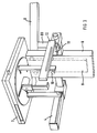
- FIG. 2 shows the same basic device, consisting of a height-adjustable support column 1, rotating unit 2 and X-ray emitter 3, but supplemented by a device which can be adapted to the device and with which remote skull images, hereinafter referred to as Ceph images, can be created.
- Ceph images remote skull images
- FIG. 3 shows the above-mentioned device for taking Ceph images in a diagrammatic representation.
- a cantilever arm 6 is attached to the height-adjustable part 1a of the support column 1 (FIG. 2) and carries a (second) head holding and positioning device 7.
- the cantilever arm 6 comprises a housing 8 on which a sword 9, which carries the head-holding and positioning device, is adjustably mounted with the aid of guide rollers 10 arranged in the housing 8.
- the line camera 4 is connected by means of a cross member 11 to a front screen 12, which serves to adjust the fan beam, which is already known per se from the secondary screen adjacent to the X-ray source 3, to the slot width and length of the line camera, which will be explained in more detail below .
- the line camera in the embodiment according to FIG. 2 is not arranged vertically but horizontally.
- a correspondingly designed holder is shown in Figure 5.
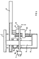
- FIG. 4 which shows the device in front view and partly in section, there is a threaded spindle 13 on the sword 9, which carries the head holding and positioning device, which interacts with a geared motor, generally designated D3.
- the geared motor D3 is attached either to the housing 8 or to the support arm 6.
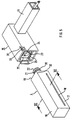
- FIG. 5 shows a line exploded view on the one hand the line camera 4 and on the other hand one designated 15 bracket, which is attached in the present application for the embodiment of Figure 2 on the cross member 11.
- a holder of the same design (without cross member 11) is attached vertically to the rotating unit 2 (FIG. 1).
- the line scan camera 4 contains an elongated housing 16, which in the exemplary embodiment consists of a square tube and has a slot 18 in the front side surface 17 facing the radiation source 3.
- the slot 18 is located in the lower third of the side surface 17, as a result of which the line camera can be moved into a comparatively low starting position (see dashed line in FIG. 2).
- a radiation-sensitive detector in the form of a two-dimensional CCD sensor behind the slot 18 in the interior of the profile tube 16.
- the mechanical connection means contain an annular groove 21 which interacts with a ball catch 23.
- the electrical connection means consist of a multi-pin connector 22 which cooperates with a socket 24 in the holder 15.
- the plug pins 22 are connected to the line detector already mentioned and to further electronics located inside the line camera 4.
- the holder 15 is constructed in such a way that when the line detector is attached, the end face 19 of the line camera 4 is opposite an end face 25 of the holder 15.
- an ejection device 26 is provided.
- this consists of a bracket which is guided to the outside in a slot in the housing wall of the holder 15. If the bracket is actuated with the line camera attached, adjacent bracket parts press against the end face 19 and thus exert a centric force on the surface, as a result of which the connection can be released easily.
- the housing 30 with a centering device which contains a lever 31 mounted eccentrically in the housing of the holder.
- the eccentric lever 31 is actuated, as a result of which a surface of the eccentric presses on the edge of the housing designated 32 in the figure and holds it in a defined, reproducible position.
- the housing is made in one piece, the housing can also be made in several parts, the one housing part carrying the detector then being centered in the aforementioned manner. This allows the detector to be fixed in relation to the holder regardless of the camera housing and its possible assembly and manufacturing tolerances.
- FIG. 6 shows a section along the line VI-VI in FIG.
- the housing is made light-tight;
- the slot 18 is covered on the end face by a light-tight, but X-ray transparent plastic plate 33.
- Behind it is inside a CCD sensor 35 provided with an upstream scintillation layer and optionally with an intermediate fiber optic.
- the CCD sensor 35 can be formed in one or more parts and advantageously as a sensor matrix made of amorphous silicon.
- a metallic holder 37 connects the carrier 36 and the CCD element 35 to a circuit board 38.
- Flexible contact strips 39 for example made of silicone provided with gold fibers, bring about this electrical contact between sensor 35 and circuit board 38.
- the circuit board 38 contains all the components which are directly necessary for controlling the CCD sensor. If necessary, further boards 38a, 38b are arranged in the housing. The lines leading from the board (s) 38 (38a, 38b) lead to the already mentioned plug pins 22 (FIG. 5). With 34 shock absorbing elements are designated, which store the detector 35 and the control boards 38, 38a, 38b 'floating' in the housing. This allows the highly sensitive and expensive parts to be largely protected against breakage or loosening of the contact connections if the camera falls down unintentionally.
- the same basic device and one and the same camera can be used for PAN recordings (FIG. 1) and Ceph recordings (FIG. 2).
- the line camera advantageously has a correspondingly longer sensor.
- the line scan camera can be attached to either the Ceph or the PAN holder as required.
- Various options are conceivable for mounting the line camera on the holder 15.
- a bayonet connection can also be provided.
- another outer shape can be provided for the housing of the line scan camera.
- a PAN layer recording is achieved in such a way that the signals obtained when the object to be scanned (jaw) is scanned are added up in the two-dimensionally resolving detector, the additions of the signals - if a CCD sensor is used - already being carried out on the sensor can by operating in TDI mode.
- This special mode of operation simulates the function of a moving film by exposure generated charge packets in the CCD element are clocked accordingly, while new charges are constantly added.
- the clock pulses for TDI operation are derived from the stepper motor pulses otherwise required for the film cassette drive.
- the Ceph recording also runs in slot technology.
- the head of a standing (or sitting) patient is swept from top to bottom (with a horizontal arrangement) or from left to right (with a vertical arrangement) vice versa with a beam fan.
- This beam fan adjusted by the already mentioned front panel 11, strikes the horizontally arranged slot of the CCD sensor.
- the entire device that is to say X-ray source 3 with primary and secondary diaphragm and line scan camera 4 with sensor, is now moved together from an initial position in the vertical (see arrows in FIG. 2).
- the head holding and positioning device 7 is moved in the opposite direction with the aid of the drive D3, the two movements being coordinated with one another in such a way that the patient's head remains spatially fixed, ie stationary.
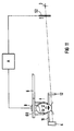
- the control of the two drive motors D1 and D3 takes place according to the block diagram according to FIG. 7 via a microprocessor 40.
- the two drives are assigned speed detection sensors 41, direction of rotation switch 42 and limit switches or correction switches 44, 45.
- the control carried out via pulse width modulation also contains safety switches 46.
- An evaluation electronics of the microcontroller 40 recognizes the holder (PAN or Ceph device) to which the camera is attached.
- the drive motor D3 moves into the starting position, for example into the lower adjustment position (dashed position in FIG. 2). Speaks in this position the limit switch 44 on.
- the head restraint positioning device can now be adjusted to the patient size by means of the height adjustment of the support column 1.
- the drive motor D3 moves the head positioning device 7 upwards, while at the same time the drive motor D1 for the support column moves downwards.
- the two drives are controlled so that the difference in the adjustment speeds is zero. This ensures that the distance between the ear tips and thus the head positioning to the floor remains constant.
- the recording is ended when the limit switch 44 or a system clock counter (TDI clock counter) detects the upper end position.
- the TDI clock for the CCD sensor is e.g. derived from the drive motor D1, which is provided for the height adjustment of the support column. Alternatively, it can also be obtained from the signals of a position counter, which measures the adjustment of the support column directly.
- the TDI mode is not used here, as with a PAN image, to create blurring and thus a layer image, but rather to use the full width of the sensor for image formation.
- the TDI operation corresponds to a film that is moved relative to the slot and is fixed relative to the patient.
- FIGS. 8 and 9 show advantageous variants of the embodiment shown in FIG. 2 on the basis of a view from above (top view).
- the line camera 4 is arranged horizontally
- the line camera 4 is arranged vertically; Accordingly, a vertical fanned beam of rays is also applied to the CCD sensor from the primary aperture and the front aperture.
- both the line camera 4 and the front panel 12 are guided in longitudinal guides 50, 51, which are motorized, for example by means of a common drive D4 or, with the interposition of a reduction gear (G), are moved by separate drives D4 and D5.
- the primary screen 52 can also be moved in the direction of the arrow by means of a longitudinal guide 53.
- a drive D6 is provided here for adjustment.
- the longitudinal guides 50, 51 and 53 can be designed in a known manner as motor-driven threaded spindle drives. The angular velocities for the drives D4, D5 and D6 are the same if separate drives are provided in each case. If a common drive is to be provided for longitudinal guides 50 and 51, the two longitudinal guides must be coupled to one another via a further spindle 55 with the interposition of a suitable reduction gear (G).
- the primary diaphragm is not moved. Rather, it rotates rigidly with the rotating unit 2 around its center of rotation 54. In this version, too, it is conceivable to synchronize the two longitudinal guides 50 and 51 with one another by means of a further spindle and a suitable reduction gear G placed between them.
- FIG. 10 shows a possible embodiment of a beam alignment, namely an asymmetrical setting of the beam with respect to the object to be irradiated.
- a symmetrical alignment of the fan beam is also possible.
- FIG. 11 shows a further advantageous embodiment in which the camera 4, as shown in FIG. 2, is arranged horizontally and is connected to the front panel 12 via a cross member 11.
- Camera 4 and front panel 12 are adjusted in a motorized manner via a drive A with primary aperture 52, the adjustment being carried out in TDI mode, as described.
- the radiation source 3 remains stationary during the adjustment movement of the camera and primary diaphragm.
- the film cassette is compared to the conventional devices which work with X-ray film and reinforcing films electronic radiation converter (2-dimensional line detector) replaced.
- the relatively narrow sensor used there receives a horizontal fan beam emitted by the X-ray emitter, the arrangement of the emitter and line detector being such that it is moved vertically past the object by, for example, adjusting the height of the stand.
- the fan beam is initially roughly delimited by the primary aperture near the radiator and then by an object or pre-aperture placed directly in front of the object and moving in the vertical movement.
- the object in the exemplary embodiment the skull to be examined, must be irradiated from at least two, advantageously from still further angular directions, the projections not being in one but in different planes in order to achieve optimal blurring. It is practicable to change the projection direction upwards, downwards, to the left and to the right, as is shown below using the various embodiments.
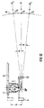
- FIGS. 12 and 13 show a first modification in which not only, as described, radiation source 3 and line detector camera 4, together with front panel 12, are vertically adjustable, that is to say by the dimension h are, but in addition, the radiator 3, which is only symbolically indicated here, is moved laterally and vertically, starting from a fixed, horizontal projection direction P.
- Figure 12 shows the vertical process of Spotlight.
- the radiator is pivoted about a horizontal axis on a predetermined circular path with the radius R, which corresponds to the distance between the radiator focus and the skull center patient.
- the pivoting takes place by a certain angular dimension ⁇ , which can be approximately between 5 to 15 °.
- An object point (OP) of the object to be irradiated (skull) is thus not only irradiated from one (usual) projection direction P, but also from other, in other planes projection directions (P1, P2, P3, P4 ...), whereby the beam fan is directed in each case at the object with the line detector camera 4 behind it.
- the object diaphragm 12 can advantageously also be moved in a correspondingly linear manner.
- the line detector can remain in its position, it can be advantageous to rotate the object diaphragm and the radiation detector. This results in a clean masking at the edges of the diaphragm and an optimal radiation detection.
- FIG 13 which shows the lateral method of (here also symbolically indicated) the radiator 3, it can be seen that the radiator, when it is pivoted from position P to P3 or P4, also about a vertical axis V is rotated.
- the angle of rotation ⁇ is such that there is always a vertical radiation of the object in the projection directions P3 and P4.
- a large-area camera with a sensor based on amorphous silicon could also be used. This could eliminate the need for strip-by-strip scanning, i.e. the entire height adjustment of the radiator, object diaphragm and detector, to create a 2D image.
- FIGS. 14 and 15 show a further embodiment.
- the radiation source 3 is not further adjusted with the exception of the height adjustment for scanning the skull.
- the spotlight, diaphragms and line detector remain fixed to each other here, while the object is tilted to create the tomosynthetic images.
- the entire head holder 7 can advantageously be tilted up and down relative to the support rod 6 by the angular amount ⁇ . With this adjustment variant, you can use the already existing setting options for the ear tips and the nose support.
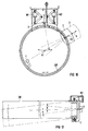
- FIGS. 16 and 17 are based on the device as described in EP-0 229 308 already mentioned at the beginning.
- a line detector camera 4 is advantageously provided, which, as shown in FIG. 1, is arranged vertically.
- the recordings for a tomosynthesis using slot technology are carried out by linearly, horizontally shifting the arrangement of the radiators 3 and sensor 4 against the object, in that the sensor 4 and the radiator 3 are actuated by respective actuators (motors M1, M2 or M3) on the rotating ring (DR). be moved in the same direction or by moving the rotating ring completely against the object.
- the radiator 3 is pivoted about a first vertical axis (V1 in FIGS.
- Different tomosynthetic projection angles in the horizontal can be set by rotating the ring around the object, using the same mechanism as is required for panoramic images.
- the different projection angles in the vertical direction can be achieved by wobbling the ring about a horizontal axis H (FIG. 17), the sensor being expediently moved during this wobbling or tilting movement.
- Another variant of this exemplary embodiment would be to arrange the sensor for the tomosynthesis not horizontally but instead horizontally.
- the sensor can be repositioned accordingly for PAN or Ceph recordings.
- the height of the patient's head would only be partially detected. If, as is useful with Ceph images, the skull should be fully covered, this can be done e.g. through successively created, vertically offset images that are subsequently put together in a precise fit on the computer. It is also conceivable to use a special X-ray tube that emits at a larger usable angle in conjunction with a correspondingly longer or larger sensor. It is particularly advantageous to radially adjust the radiator for these recordings on the ring and thus to bring them at a greater distance from the object. 16, this adjustment option is indicated by a double arrow (A) on the radiator 3.
- the skull and the x-ray sensor are usually located at a distance from the panorama device that contains the radiator.
- the reason for this is to keep distortion from the central projection small. If you shorten the boom, the distortions increase accordingly, ie approximately when the skull is viewed from the side, the radiator half near the radiator is shown larger than the radiator half.
- such an arrangement can also be used to create skull recordings and prepare them tomosynthetically if the slice images are calculated in layers close to or far from the radiator.
- the images can be reproduced as undistorted slice images or 3D images, or they can be mathematically combined and reproduced to form the usual undistorted total absorption image.
- This solution is advantageous because it does not require a separate CEPH body with a boom.
Abstract
Description
Die Erfindung bezieht sich auf eine zahnärztliche Röntgendiagnostikeinrichtung zur Erstellung von tomosynthetischen Bildern von Objekten eines Patienten.The invention relates to a dental X-ray diagnostic device for creating tomosynthetic images of objects of a patient.
Bei der Tomosynthese wird ein Objekt aus verschiedenen Projektionsrichtungen durchstrahlt und danach die entstehenden 2D-Bilder in einem Rechner zu Schichtaufnahmen und 3D-Bildern verarbeitet. Die Aufnahme der Bilder kann in herkömmlicher Weise auf Filmmaterial erfolgen oder auch über elektronische Bildwandler (Röntgenbildverstärker, CCD-Kamera oder Digitalkamera auf Basis von amorphem Silizium).In tomosynthesis, an object is irradiated from different projection directions and then the resulting 2D images are processed in a computer to produce slice images and 3D images. The images can be recorded in the conventional manner on film material or also via electronic image converters (X-ray image intensifier, CCD camera or digital camera based on amorphous silicon).
Der im Anspruch 1 angegebenen Erfindung liegt die Aufgabe zugrunde, eine zahnärztliche Röntgendiagnostikeinrichtung anzugeben, mit der es möglich ist, mit relativ geringem Aufwand tomosynthetische Aufnahmen erstellen zu können. Die Erfindung fußt auf der Erkenntnis, die wesentlichen Komponenten in der Orthopanthomographie und in der Cephalometrie bekannten Geräte zu nutzen und durch geeignete Zusatzelemente so zu modifizieren, daß die vorgenannten Aufnahmen mit geringem Aufwand zu erstellen sind. Eine weitere Zielsetzung liegt in der Abwandlung eines Panorama-Röntgengerätes zum Zwecke der Erzeugung von Fernröntgenbildern des Schädels herkömmlicher Art, d.h. Darstellung der Summenabsorption bei kompletter Durchstrahlung des Schädels unter Verwendung tomosynthetischer Rechenverfahren.The invention specified in
Hinsichtlich des Aufbaus herkömmlicher Panorama(PAN)-Röntgenaufnahmevorrichtungen sowie Vorrichtungen zur Erstellung von Schädelaufnahmen (Ceph-Aufnahmen) wird auf die EP-A-0 229 308 verwiesen.With regard to the construction of conventional panorama (PAN) X-ray imaging devices and devices for creating skull images (Ceph images), reference is made to EP-A-0 229 308.
Anhand der Figuren 1 bis 11 der Zeichnung wird zunächst der Grundaufbau verschiedener Varianten beschrieben, mit denen sich Röntgenaufnahmen ohne Film und Filmkassette erstellen lassen. Die darauffolgenden Figuren 12 bis 17 zeigen Modifikationen dieser Ausführungsformen, mit denen sich mit relativ geringem Aufwand die eingangs genannten tomosynthetischen Röntgenaufnahmen erstellen lassen.With reference to Figures 1 to 11 of the drawing, the basic structure of various variants is first described, with which X-rays can be taken without a film and film cassette. The subsequent FIGS. 12 to 17 show modifications of these embodiments, with which the tomosynthetic X-ray recordings mentioned at the outset can be produced with relatively little effort.
Die Figur 1 zeigt in einer Prinzipdarstellung ein zahnärztliches Röntgendiagnostikgerät zur Erstellung von Panorama-Schichtaufnahmen, nachfolgend kurz mit PAN-Aufnahmen bezeichnet. Das Gerät enthält eine in der Höhe verstellbare Tragsäule 1, an der eine Dreheinheit 2 gehaltert ist, die Träger einerseits einer Röntgenstrahlenquelle 3 und andererseits diametral dazu einer Röntgenzeilenkamera 4 ist. Mit 5 ist eine (erste) Kopfhalte- und Positioniereinrichtung bezeichnet, mit der in bekannter Weise der Patientenkopf in einer definierten Position fixiert werden kann. Aufbau sowie Verstellmöglichkeiten der Dreheinheit und der Kopfhalte- und Positioniereinrichtung sind bekannt und beispielsweise in der EP-0 229 308 beschrieben.FIG. 1 shows a basic illustration of a dental X-ray diagnostic device for creating panoramic slice images, hereinafter briefly referred to as PAN images. The device contains a height-
Die Figur 2 zeigt das gleiche Grundgerät, bestehend aus höhenverstellbarer Tragsäule 1, Dreheinheit 2 und Röntgenstrahler 3, ergänzt jedoch durch eine am Gerät adaptierbare Vorrichtung, mit der sich Schädelfernaufnahmen, nachfolgend kurz Ceph-Aufnahmen, erstellen lassen. Bevor die genannte Vorrichtung näher erläutert wird, sei noch erwähnt, daß die Tragsäule 1 mittels eines Antriebes D1 in der angegebenen Pfeilrichtung höhenverstellbar ausgebildet ist, daß weiterhin in bekannter Weise die Dreheinheit 2 mittels eines oder mehrerer Antriebe D2 gedreht und geschwenkt werden kann, um eine PAN-Aufnahme machen zu können. Einzelheiten hierzu ergeben sich aus der bereits genannten EP-0 229 308.FIG. 2 shows the same basic device, consisting of a height-
Die Figur 3 zeigt die vorgenannte Vorrichtung zur Erstellung von Ceph-Aufnahmen in einer schaubildlichen Darstellung.FIG. 3 shows the above-mentioned device for taking Ceph images in a diagrammatic representation.
Am höhenverstellbaren Teil 1a der Tragsäule 1 (Fig. 2) ist ein Auslegerarm 6 befestigt, der eine (zweite) Kopfhalte- und Positoniereinrichtung 7 trägt. Der Auslegerarm 6 umfaßt ein Gehäuse 8, an dem ein Schwert 9, welches die Kopf-halte- und Positioniereinrichtung trägt, mit Hilfe von im Gehäuse 8 angeordneten Führungsrollen 10 verstellbar gelagert ist. Die Zeilenkamera 4 ist mittels eines Querträgers 11 mit einer Vorblende 12 verbunden, die dazu dient, den an sich schon in bekannter Weise von der der Röntgenstrahlenquelle 3 benachbarten Sekundärblende begrenzten Fächerstrahl nochmals exakt auf die Schlitzbreite und -länge der nachfolgend noch näher erläuterten Zeilenkamera zu justieren.A
Im Gegensatz zum Ausführungsbeispiel nach Figur 1 ist die Zeilenkamera bei der Ausführung nach Figur 2 nicht vertikal, sondern waagerecht angeordnet. Eine entsprechend ausgebildete Halterung ist in Figur 5 dargestellt.In contrast to the exemplary embodiment according to FIG. 1, the line camera in the embodiment according to FIG. 2 is not arranged vertically but horizontally. A correspondingly designed holder is shown in Figure 5.
Wie aus Figur 4, die die Vorrichtung in Frontansicht und teilweise im Schnitt zeigt, ersichtlich, befindet sich am Schwert 9, welches die Kopfhalte- und Positioniereinrichtung trägt, eine Gewindespindel 13, die mit einem allgemein mit D3 bezeichneten Getriebemotor zusammenwirkt. Der Getriebemotor D3 ist entweder am Gehäuse 8 oder am Tragarm 6 befestigt. Wie später noch näher erläutert, wird mit Hilfe der aufgezeigten Verstellanordnung mit dem Antrieb D3 erreicht, daß, wenn die Röntgenstrahlenquelle 3 zusammen mit der Zeilenkamera 4 in der Vertikalen bewegt wird, die Kopfhalte- und Positioniereinrichtung 7 während der Ceph-Aufnahme effektiv keine Bewegung ausführt, d.h. ortsfest im Raum gehalten wird.As can be seen from FIG. 4, which shows the device in front view and partly in section, there is a threaded
Die Figur 5 zeigt in einer schaubildlichen Explosionsdarstellung einerseits die Zeilenkamera 4 und andererseits eine mit 15 bezeichnete Halterung, die im vorliegenden Anwendungsfalle für die Ausführung nach Figur 2 am Querträger 11 befestigt ist. Im Falle der Version nach Figur 1 (für PAN-Aufnahmen) ist eine gleich ausgebildete Halterung (ohne Querträger 11) senkrecht an der Dreheinheit 2 (Figur 1) befestigt.FIG. 5 shows a line exploded view on the one hand the
Die Zeilenkamera 4 enthält ein längliches Gehäuse 16, welches im Ausführungsbeispiel aus einem Vierkantrohr besteht und in der vorderen, der Strahlenquelle 3 zugewandten Seitenfläche 17 einen Schlitz 18 aufweist. Der Schlitz 18 befindet sich im unteren Drittel der Seitenfläche 17, wodurch die Zeilenkamera in eine vergleichsweise tiefe Ausgangsposition (sh. gestrichelte Darstellung in Fig. 2) gefahren werden kann.The
Wie aus Figur 6 noch näher hervorgeht, befindet sich hinter dem Schlitz 18 im Innern des Profilrohres 16 ein strahlenempfindlicher Detektor in Form eines zweidimensionalen CCD-Sensors. An der einen Stirnseite 19 befindet sich ein zapfenförmiges Anschlußelement 20, welches mechanische und elektrische Anschlußmittel für eine elektrische und mechanische Verbindung mit dem Halter 15 aufweist. Die mechanischen Anschlußmittel enthalten eine Ringnut 21, die mit einer Kugelrastung 23 zusammenwirkt. Die elektrischen Anschlußmittel bestehen aus einem Mehrstiftstecker 22, der mit einer Steckbuchse 24 im Halter 15 zusammenwirkt. Die Steckstifte 22 sind mit dem bereits erwähnten Zeilendetektor und einer weiteren, im Inneren der Zeilenkamera 4 befindlichen Elektronik verbunden. Der Halter 15 ist so aufgebaut, daß bei aufgesetztem Zeilendetektor die Stirnseite 19 der Zeilenkamera 4 einer stirnseitigen Anschlußfläche 25 der Halterung 15 gegenübersteht.As can be seen from FIG. 6, there is a radiation-sensitive detector in the form of a two-dimensional CCD sensor behind the
Damit das Lösen der Zeilenkamera 4 von der Halterung 15 erleichtert ist, insbesondere ein Verkanten und damit die Gefahr einer Beschädigung der hochempfindlichen elektrischen Kontakte vermieden wird, ist eine Auswurfeinrichtung 26 vorgesehen. Diese besteht in der vorliegenden Ausführungsform aus einem Bügel, der in einem Schlitz der Gehäusewandung des Halters 15 nach außen geführt ist. Wird der Bügel bei aufgesetzter Zeilenkamera betätigt, drücken anliegende Bügelteile gegen die Stirnfläche 19 und üben so eine zentrische Kraft auf die Fläche aus, wodurch die Verbindung leicht gelöst werden kann.So that the release of the
Mit 30 ist eine Zentriereinrichtung bezeichnet, die einen exzentrisch im Gehäuse der Halterung gelagerten Hebel 31 enthält. Nach Einsetzen der Zeilenkamera 4 in den Halter 15 wird der Exzenterhebel 31 betätigt, wodurch eine Fläche des Exzenters auf die in der Figur mit 32 bezeichnete Kante des Gehäuses drückt und dieses in definierter, reproduzierbarer Position hält. Obgleich im vorliegenden Ausführungsbeispiel das Gehäuses einteilig ausgebildet ist, kann das Gehäuse auch mehrteilig ausgeführt sein, wobei der eine, den Detektor tragende Gehäuseteil dann in der vorgenannten Weise zentriert wird. Damit kann der Detektor unabhängig vom Kameragehäuse und dessen etwaigen Montage- und Fertigungstoleranzen in bezug auf den Halter fixiert werden.30 with a centering device is referred to, which contains a
Aus Figur 6, die einen Schnitt entlang der Linie VI-VI in Figur 5 zeigt, geht der prinzipielle Aufbau der Zeilenkamera hervor. Das Gehäuse ist lichtdicht ausgebildet; der Schlitz 18 ist stirnseitig von einer lichtdichten, aber röntgenstrahlendurchlässigen Kunststoffplatte 33 bedeckt. Dahinter befindet sich im Innern ein mit einer vorgeschalteten Szintillationsschicht und gegebenenfalls mit einer zwischengeschalteten Faseroptik versehener CCD-Sensor 35. Der CCD-Sensor 35 kann ein- oder mehrteilig und vorteilhafterweise als Sensormatrix aus amorphem Silizium ausgebildet sein. Ein metallischer Halter 37 verbindet den Träger 36 und das CCD-Element 35 mit einer Platine 38. Flexible Kontaktstreifen 39, z.B. aus mit Goldfasern versehenem Silicon, bewirken den elektrischen Kontakt zwischen Sensor 35 und Platine 38. Die Platine 38 enthält sämtliche, zur Ansteuerung des CCD-Sensors unmittelbar erforderlichen Bauelemente. Gegebenenfalls sind im Gehäuse noch weitere Platinen 38a, 38b angeordnet. Die von der (den) Platine(n) 38 (38a, 38b) abgehenden Leitungen führen zu den bereits erwähnten Steckstiften 22 (Fig. 5). Mit 34 sind stoßabsorbierende Elemente bezeichnet, die den Detektor 35 und die Steuerplatinen 38, 38a, 38b im Gehäuse 'schwimmend' lagern. Damit lassen sich die hochempfindlichen und teueren Teile bei einem unbeabsichtigten Herabfallen der Kamera vor Bruch bzw. Lösen der Kontaktverbindungen weitgehend schützen.The basic structure of the line scan camera is shown in FIG. 6, which shows a section along the line VI-VI in FIG. The housing is made light-tight; The
Wie eingangs bereits erwähnt, ist für PAN-Aufnahmen (Fig. 1) und Ceph-Aufnahmen (Fig. 2) das gleiche Grundgerät und ein und dieselbe Kamera verwendbar. Um die für eine Ceph-Aufnahme nötige Bildgröße zu erreichen, hat die Zeilenkamera vorteilhafterweise einen entsprechend längeren Sensor. Die Zeilenkamera kann so je nach Bedarf entweder am Ceph- oder am PAN-Halter angebracht werden. Zur Halterung der Zeilenkamera am Halter 15 sind verschiedene Möglichkeiten denkbar. Anstelle der gezeigten Kugelrastung kann auch eine Bajonettverbindung vorgesehen sein. Desgleichen kann anstelle eines Vierkantprofiles eine andere äußere Formgestaltung für das Gehäuse der Zeilenkamera vorgesehen sein.As already mentioned at the beginning, the same basic device and one and the same camera can be used for PAN recordings (FIG. 1) and Ceph recordings (FIG. 2). In order to achieve the image size required for a Ceph image, the line camera advantageously has a correspondingly longer sensor. The line scan camera can be attached to either the Ceph or the PAN holder as required. Various options are conceivable for mounting the line camera on the
Zum Aufnahmeprinzip wird folgendes angemerkt:
Eine PAN-Schichtaufnahme wird in der Weise erzielt, daß die beim Überstreichen des aufzunehmenden Objekts (Kiefer) gewonnenen Signale in dem zweidimensional auflösenden Detektor aufaddiert werden, wobei das Aufaddieren der Signale - falls ein CCD-Sensor verwendet wird - bereits auf dem Sensor durchgeführt werden kann, indem dieser im TDI-Modus betrieben wird. Durch diese besondere Betriebsart wird die Funktion eines bewegten Filmes nachgebildet, indem die durch Belichtung erzeugten Ladungspakete im CCD-Element entsprechend weitergetaktet werden, während ständig neue Ladungen hinzukommen. Die Taktimpulse für den TDI-Betrieb werden aus den sonst für den Filmkassettenantrieb erforderlichen Schrittmotorimpulsen abgeleitet.The following is noted regarding the admission principle:
A PAN layer recording is achieved in such a way that the signals obtained when the object to be scanned (jaw) is scanned are added up in the two-dimensionally resolving detector, the additions of the signals - if a CCD sensor is used - already being carried out on the sensor can by operating in TDI mode. This special mode of operation simulates the function of a moving film by exposure generated charge packets in the CCD element are clocked accordingly, while new charges are constantly added. The clock pulses for TDI operation are derived from the stepper motor pulses otherwise required for the film cassette drive.
Alternativ ist auch ein Aufaddieren in einer späteren Signalverarbeitungsstufe möglich.Alternatively, an addition in a later signal processing stage is also possible.
Die Ceph-Aufnahme läuft ebenfalls in Slot-Technik ab. Der Kopf eines stehenden (oder sitzenden) Patienten wird je nach Anordnung der Zeilenkamera von oben nach unten (bei waagerechter Anordnung) oder von links nach rechts (bei senkrechter Anordnung) vice versa mit einem Strahlfächer überstrichen. Dieser Strahlfächer trifft, justiert durch die bereits genannte Vorblende 11, genau auf den waagerecht angeordneten Schlitz des CCD-Sensors. Mit Hilfe des Antriebs D1 verfährt man nun das gesamte Gerät, also Röntgenstrahlenquelle 3 mit Primär- und Sekundärblende sowie Zeilenkamera 4 mit Sensor, gemeinsam von einer Ausgangsposition aus in der Vertikalen (sh. Pfeile in Fig. 2). Gleichzeitig wird die Kopfhalte- und Positioniereinrichtung 7 mit Hilfe des Antriebs D3 in Gegenrichtung gefahren, wobei die beiden Bewegungen so aufeinander abgestimmt sind, daß der Patientenkopf räumlich fixiert, d.h. ortsfest, bleibt. Die Steuerung der beiden Antriebsmotoren D1 und D3 erfolgt entsprechend dem Blockschaltbild nach Figur 7 über einen Mikroprozessor 40. Den beiden Antrieben sind Drehzahlerkennungssensoren 41, Drehrichtungsumschalter 42 sowie End- bzw. Korrekturschalter 44, 45 zugeordnet. Die über Pulsweitenmodulation erfolgte Steuerung enthält weiterhin Sicherheitsschalter 46. Eine Auswerteelektronik des Mikro-Controllers 40 erkennt, an welcher Halterung (PAN- oder Ceph-Gerät) die Kamera befestigt ist. Wird eine Ceph-Aufnahme angewählt, fährt der Antriebsmotor D3 in die Ausgangsposition, beispielsweise in die untere Verstellposition (gestrichelte Position in Fig. 2). In dieser Position spricht der Endschalter 44 an. Mittels der Höhenverstellung der Tragsäule 1 kann nun die Kopfhaltepositoniereinrichtung auf die Patientengröße eingestellt werden. Während der Ceph-Aufnahme verfährt der Antriebsmotor D3 die Kopfpositioniereinrichtung 7 nach oben, während gleichzeitig der Antriebsmotor D1 für die Tragsäule nach unten fährt. Die beiden Antriebe werden dabei so geregelt, daß die Differenz der Verstellgeschwindigkeiten gleich Null ist. Dadurch ist sichergestellt, daß der Abstand der Ohroliven und damit der Kopfpositionierung zum Fußboden konstant bleibt. Die Aufnahme ist beendet, wenn der Endschalter 44 oder ein Systemtakt-Zähler (TDI-Takt-Zähler) die obere Endlage erkennt.The Ceph recording also runs in slot technology. Depending on the arrangement of the line scan camera, the head of a standing (or sitting) patient is swept from top to bottom (with a horizontal arrangement) or from left to right (with a vertical arrangement) vice versa with a beam fan. This beam fan, adjusted by the already mentioned
Der TDI-Takt für den CCD-Sensor wird z.B. vom Antriebsmotor D1, der für die Höhenverstellung der Tragsäule vorgesehen ist, abgeleitet. Alternativ kann er auch aus den Signalen eines Positionszählers, der die Verstellung der Tragsäule direkt mißt, gewonnen werden. Der TDI-Modus dient hier nicht, wie bei einer PAN-Aufnahme, um eine Verwischung und damit eine Schichtaufnahme zu erzeugen, sondern dazu, die volle Breite des Sensors zur Bildentstehung auszunutzen. Hier entspricht also der TDI-Betrieb einem Film, der relativ zum Schlitz bewegt wird und relativ zum Patienten feststeht.The TDI clock for the CCD sensor is e.g. derived from the drive motor D1, which is provided for the height adjustment of the support column. Alternatively, it can also be obtained from the signals of a position counter, which measures the adjustment of the support column directly. The TDI mode is not used here, as with a PAN image, to create blurring and thus a layer image, but rather to use the full width of the sensor for image formation. Here, the TDI operation corresponds to a film that is moved relative to the slot and is fixed relative to the patient.
Die nachfolgenden Figuren zeigen vorteilhafte Varianten zu der in Figur 2 dargestellten Ausführungsform anhand einer Ansicht von oben (Draufsicht). Im Gegensatz zu der Ausführung nach Figur 2, bei der die Zeilenkamera 4 horizontal angeordnet ist, ist bei den Varianten nach Figuen 8 und 9 die Zeilenkamera 4 vertikal angeordnet; demnach wird auch von der Primärblende und der Vorblende ein vertikales gefächertes Strahlenbündel auf den CCD-Sensor gegeben.The following figures show advantageous variants of the embodiment shown in FIG. 2 on the basis of a view from above (top view). In contrast to the embodiment according to FIG. 2, in which the
Bei der Ausführung nach Figur 8 ist sowohl die Zeilenkamera 4 als auch die Vorblende 12 in Längsführungen 50, 51 geführt, die motorisch z.B. mittels eines gemeinsamen Antriebes D4 oder, unter Zwischenschaltung eines Untersetzungsgetriebes (G) durch getrennte Antriebe D4 und D5 bewegt werden. Die Primärblende 52 ist ebenfalls mittels einer Längsführung 53 in Pfeilrichtung bewegbar. Zur Verstellung ist hier ein Antrieb D6 vorgesehen. Die Längsführungen 50, 51 und 53 können in bekannter Weise als motorisch angetriebene Gewindespindelantriebe ausgebildet sein. Die Winkelgeschwindigkeiten für die Antriebe D4, D5 und D6 sind dann, wenn jeweils getrennte Antriebe vorgesehen sind, gleich. Wenn für Längsführungen 50 und 51 ein gemeinsamer Antrieb vorgesehen werden soll, müssen die beiden Längsführungen über eine weitere Spindel 55 unter Zwischenschaltung eines geeigneten Untersetzungsgetriebes (G) miteinander gekoppelt sein.In the embodiment according to FIG. 8, both the
Bei der Ausführung gemäß Figur 9 wird die Primärblende nicht bewegt. Sie läuft vielmehr starr mit der Dreheinheit 2 um deren Drehmittelpunkt 54 um. Auch bei dieser Version ist es denkbar, die beiden Längsführungen 50 und 51 durch eine weitere Spindel und ein geeignetes, dazwischen gesetztes Untersetzungsgetriebe G miteinander zu synchronisieren.In the embodiment according to FIG. 9, the primary diaphragm is not moved. Rather, it rotates rigidly with the
Die Figur 10 zeigt eine mögliche Ausführung einer Strahlausrichtung, nämlich eine asymmetrische Einstellung des Strahles in bezug auf das zu durchstrahlende Objekt. Anstelle der asymmetrischen Einstellung ist auch eine symmetrische Ausrichtung des Fächerstrahls möglich.FIG. 10 shows a possible embodiment of a beam alignment, namely an asymmetrical setting of the beam with respect to the object to be irradiated. Instead of the asymmetrical setting, a symmetrical alignment of the fan beam is also possible.
Die Figur 11 zeigt eine weitere vorteilhafte Ausführungsform, bei der die Kamera 4, wie in Figur 2 gezeigt, horizontal angeordnet und über einen Querträger 11 mit der Vorblende 12 verbunden ist. Kamera 4 und Vorblende 12 werden gemeinsam über einen Antrieb A mit der Primärblende 52 motorisch verstellt, wobei die Verstellung, wie beschrieben, im TDI-Modus erfolgt. Die Strahlenquelle 3 bleibt bei dieser Ausführungsform während der Verstellbewegung von Kamera und Primärblende ortsfest.FIG. 11 shows a further advantageous embodiment in which the
Wie aus einem Vergleich der Vorrichtung, wie sie in der eingangs zitierten EP-A-0 229 308 beschrieben ist, mit den Ausführungsformen der zuvor beschriebenen Figuren 1 bis 11 hervorgeht, ist gegenüber den herkömmlichen, mit Röntgenfilm und Verstärkungsfolien arbeitenden Geräten die Filmkassette durch einen elektronischen Strahlungswandler (2-dimensionaler Zeilendetektor) ersetzt. Der relativ schmale, dort eingesetzte Sensor empfängt einen vom Röntgenstrahler abgegebenen waagerechten Fächerstrahl, wobei die Anordnung von Strahler und Zeilendetektor so getroffen ist, daß sie durch beispielsweise eine Höhenverstellung des Gerätestativs vertikal am Objekt vorbeibewegt wird. Der Fächerstrahl wird dabei zunächst grob durch die strahlernahe Primärblende und danach durch eine unmitttelbar vor dem Objekt plazierte, in der vertikalen Bewegung mitbewegte Objekt- oder Vorblende scharf begrenzt.As can be seen from a comparison of the device, as described in EP-A-0 229 308 cited at the outset, with the embodiments of FIGS. 1 to 11 described above, the film cassette is compared to the conventional devices which work with X-ray film and reinforcing films electronic radiation converter (2-dimensional line detector) replaced. The relatively narrow sensor used there receives a horizontal fan beam emitted by the X-ray emitter, the arrangement of the emitter and line detector being such that it is moved vertically past the object by, for example, adjusting the height of the stand. The fan beam is initially roughly delimited by the primary aperture near the radiator and then by an object or pre-aperture placed directly in front of the object and moving in the vertical movement.
Für die Tomosynthese muß das Objekt, im Ausführungsbeispiel der zu untersuchende Schädel, aus wenigstens zwei, vorteilhafterweise aus noch weiteren Winkelrichtungen durchstrahlt werden, wobei zur Erzielung einer optimalen Verwischung die Projektionen nicht in einer, sondern in verschiedenen Ebenen liegen sollten. Praktikabel scheint, wie dies nachfolgend anhand der verschiedenen Ausführungsformen dargestellt ist, die Projektionsrichtung nach oben, unten, links und rechts zu verändern.For tomosynthesis, the object, in the exemplary embodiment the skull to be examined, must be irradiated from at least two, advantageously from still further angular directions, the projections not being in one but in different planes in order to achieve optimal blurring. It is practicable to change the projection direction upwards, downwards, to the left and to the right, as is shown below using the various embodiments.
Die Figuren 12 und 13 zeigen in Anlehnung an die Ausführungsform gemäß Figur 2 eine erste Modifikation, bei der nicht nur, wie beschrieben, Strahlenquelle 3 und Zeilendetektorkamera 4 zusammen mit Vorblende 12 in der Höhe, also um das Maß h, in vertikaler Richtung verstellbar angeordnet sind, sondern bei der darüber hinaus, der hier nur symbolisch angedeutete Strahler 3, ausgehend von einer festen, waagerechten Projektionsrichtung P, seitlich und senkrecht verfahren wird. Figur 12 zeigt das senkrechte Verfahren des Strahlers. Der Strahler wird dabei auf einer vorgegebenen Kreisbahn mit dem Radius R, der dem Abstand zwischen Strahler-Fokus und Schädelmitte-Patient entspricht, um eine horizontale Achse geschwenkt. Das Verschwenken erfolgt um ein bestimmtes Winkelmaß α, der etwa zwischen 5 bis 15° liegen kann. Ein Objektpunkt ( OP )des zu durchstrahlenden Objekts (Schädel) wird also nicht nur aus der einen (üblichen) Projektionsrichtung P, sondern noch aus weiteren, in anderen Ebenen liegenden Projektionsrichtungen (P₁, P₂, P₃, P₄...) durchstrahlt , wobei der Strahlenfächer jeweils auf das Objekt mit der dahinterliegenden Zeilendetektorkamera 4 gerichtet ist. Die Objektblende 12 kann vorteilhafterweise entsprechend linear mit verschoben werden. Obgleich der Zeilendetektor in seiner Position verbleiben kann, kann es vorteilhaft sein, Objektblende und Strahlendetektor mitzudrehen. Dadurch erhält man eine saubere Ausblendung an den Blendenkanten und eine optimale Strahlendetektion.Based on the embodiment according to FIG. 2, FIGS. 12 and 13 show a first modification in which not only, as described,
In Betrachtung der Figur 13, die das seitliche Verfahren des (hier ebenfalls nur symbolisch angedeuteten) Strahlers 3 aufzeigt, ist erkennbar, daß der Strahler, wenn er von der Position P aus nach P₃ oder P₄ geschwenkt wird, auch noch um eine vertikale Achse V gedreht wird. Der Drehwinkel β ist so bemessen, daß in den Projektionsrichtungen P₃ und P₄ stets eine senkrechte Durchstrahlung des Objekts gegeben ist.Looking at Figure 13, which shows the lateral method of (here also symbolically indicated) the
In Abwandlung der erläuterten Ausführungsform könnte anstelle der Abtastung mittels der Zeilendetektorkamera 4 in der zuvor beschriebenen Slot-Technik mit streifenweisem Aufbau des Flächenbildes auch eine großflächige Kamera mit einem Sensor auf der Basis von amorphem Silizium verwendet werden. Dadurch könnte das streifenweise Abtasten, also die gesamte Höhenverstellung von Strahler, Objektblende und Detektor, zur Erstellung eines 2D-Bildes entfallen.In a modification of the described embodiment, instead of scanning by means of the
Die Figuren 14 und 15 zeigen eine weitere Ausführungsform. Im Gegensatz zu dem zuvor beschriebenen Ausführungsbeispiel wird die Strahlenquelle 3 mit Ausnahme der Höhenverstellung zur Abtastung des Schädels nicht weiter verstellt. Strahler, Blenden und Zeilendetektor bleiben hier also zueinander fixiert, während das Objekt zur Erstellung der tomosynthetischen Aufnahmen gekippt wird. Hierzu kann vorteilhafterweise der gesamte Kopfhalter 7 gegenüber der Tragstange 6 um den Winkelbetrag α nach oben und unten gekippt werden. Bei dieser Verstellvariante kann man die ohnehin bereits vorhandenen Einstellmöglichkeiten für die Ohroliven und die Nasenstütze verwenden.FIGS. 14 and 15 show a further embodiment. In contrast to the exemplary embodiment described above, the
Die Modifikationen gemäß den Figuren 16 und 17 basieren auf der Vorrichtung, wie sie in der eingangs bereits genannten EP-0 229 308 beschrieben ist. Anstelle der Filmkassette ist vorteilhafterweise eine Zeilendetektorkamera 4 vorgesehen, die, wie in Fig. 1 dargestellt , vertikal angeordnet ist. Die Aufnahmen für eine Tomosynthese in Slot-Technik erfolgt durch lineares, horizontales Verschieben der Anordnung Strahler 3 und Sensor 4 gegen das Objekt, indem der Sensor 4 und der Strahler 3 durch jeweilige Aktuatoren (Motoren M1, M2 oder M3) am Drehring (DR) gleichsinnig bewegt werden oder indem der Drehring komplett gegen das Objekt verschoben wird. Vorteilhafterweise wird der Strahler 3 um eine strahlerferne erste Vertikalachse (V1 in Figuren 13 und 16) auf einer vorgegebenen Kreisbahn geschwenkt und gleichzeitig und gegensinnig um eine strahlernahe zweite Vertikalachse (V2 in Figuren 13 und 16) gedreht. Vorteilhaft kann es auch sein, bei am Drehring fixiertem Strahler den Sensor zu schwenken, z.B. am Ring entlang um den Röhrenfokus als Drehpunkt. Des weiteren ist es denkbar, den Sensor linear zu verstellen, wobei entweder nur die (strahlernahe) Primärblende entsprechend mitbewegt oder Blende und Strahler mitgedreht werden.The modifications according to FIGS. 16 and 17 are based on the device as described in EP-0 229 308 already mentioned at the beginning. Instead of the film cassette, a
Unterschiedliche tomosynthetische Projektionswinkel in der Horizontalen können durch Drehen des Ringes um das Objekt eingestellt werden, und zwar mit gleicher Mechanik, wie sie für Panorama-Aufnahmen erforderlich sind. Die verschiedenen Projektionswinkel in vertikaler Richtung können durch Taumeln des Ringes um eine Horizontalachse H (Fig. 17) erzielt werden, wobei bei dieser Taumel- oder Kippbewegung der Sensor zweckmäßigerweise mitbewegt wird.Different tomosynthetic projection angles in the horizontal can be set by rotating the ring around the object, using the same mechanism as is required for panoramic images. The different projection angles in the vertical direction can be achieved by wobbling the ring about a horizontal axis H (FIG. 17), the sensor being expediently moved during this wobbling or tilting movement.
Eine weitere Variante zu diesem Ausführungsbeispiel wäre, den Sensor für die Tomosynthese nicht vertikal, sondern horizontal anzuordnen. Für PAN- oder Ceph-Aufnahmen kann der Sensor entsprechend umpositioniert werden.Another variant of this exemplary embodiment would be to arrange the sensor for the tomosynthesis not horizontally but instead horizontally. The sensor can be repositioned accordingly for PAN or Ceph recordings.
Unter den geometrischen Verhältnissen (Abstände, Winkel) der üblichen Anordnung für Panoramaaufnahmen würde der Kopf des Patienten in der Höhe nur teilweise erfaßt werden. Wenn, wie bei Ceph-Aufnahmen sinnvoll, der Schädel voll erfaßt werden soll, kann man dies z.B. durch nacheinander erstellte, höhenversetzte Bilder, die im Rechner nachträglich paßgenau zusammengesetzt werden, erreichen. Auch ist es denkbar, eine spezielle, unter größerem nutzbaren Winkel abstrahlende Röntgenröhre in Verbindung mit einem entsprechend längeren bzw. größeren Sensor zu verwenden. Besonders vorteilhaft ist es, den Strahler für diese Aufnahmen am Ring radial zu verstellen und so in einen größeren Abstand zum Objekt zu bringen. In der Fig. 16 ist diese Verstellmöglichkeit durch einen Doppelpfeil (A) am Strahler 3 angedeutet.Under the geometric conditions (distances, angles) of the usual arrangement for panorama shots, the height of the patient's head would only be partially detected. If, as is useful with Ceph images, the skull should be fully covered, this can be done e.g. through successively created, vertically offset images that are subsequently put together in a precise fit on the computer. It is also conceivable to use a special X-ray tube that emits at a larger usable angle in conjunction with a correspondingly longer or larger sensor. It is particularly advantageous to radially adjust the radiator for these recordings on the ring and thus to bring them at a greater distance from the object. 16, this adjustment option is indicated by a double arrow (A) on the
Bei den Lösungen gemäß den Figuren 12 bis 15, die dazu dienen, Ceph-Aufnahmen, also Aufnahmen vom gesamten Schädel eines Patienten, machen zu können, befinden sich Schädel und Röntgensensor üblicherweise entfernt vom Panoramagerät, das den Strahler beinhaltet. Der Grund hierfür ist, Verzerrung durch die Zentralprojektion klein zu halten. Verkürzt man den Ausleger, wachsen entsprechend die Verzerrungen, d.h. etwa bei einer Seitenaufnahme des Schädels wird die strahlernahe Kieferhälfte größer dargestellt als die strahlerferne.In the solutions according to FIGS. 12 to 15, which serve to be able to take ceph images, that is to say images of the entire skull of a patient, the skull and the x-ray sensor are usually located at a distance from the panorama device that contains the radiator. The reason for this is to keep distortion from the central projection small. If you shorten the boom, the distortions increase accordingly, ie approximately when the skull is viewed from the side, the radiator half near the radiator is shown larger than the radiator half.
Eine Extremsituation entsteht, wenn auf den Ausleger ganz verzichtet wird und der Röntgensensor an der Stelle, wie er bei der Panoramaaufnahme üblich, angeordnet wird (Figur 1).An extreme situation arises when the boom is completely dispensed with and the X-ray sensor is arranged at the location as is customary in the panorama image (FIG. 1).
Erfindungsgemäß lassen sich auch mit einer solchen Anordnung Schädelaufnahmen erstellen und tomosynthetisch aufbereiten, wenn man die Schichtbilder in Schichten strahlernah bis strahlerfern berechnet.According to the invention, such an arrangement can also be used to create skull recordings and prepare them tomosynthetically if the slice images are calculated in layers close to or far from the radiator.
Da der Abstand des Zeilendetektors vom Strahler bekannt ist, können die Verzerrungen rechnerisch korrigiert werden. Die Bilder können als unverzerrte Schichtbilder oder 3D-Bilder wiedergegeben werden oder wieder zum gewohnten unverzerrten Summenabsorptionsbild rechnerisch zusammengesetzt und wiedergegeben werden.Since the distance of the line detector from the radiator is known, the distortions can be corrected by calculation. The images can be reproduced as undistorted slice images or 3D images, or they can be mathematically combined and reproduced to form the usual undistorted total absorption image.
Diese Lösung ist deshalb vorteilhaft, da hierbei kein gesonderter CEPH-Aufbau mit Ausleger gebraucht wird.This solution is advantageous because it does not require a separate CEPH body with a boom.
Claims (18)
dadurch gekennzeichnet, daß zum Einstellen der Projektionsrichtungen (P₁, P₂ ...) der Strahler (3) um eine Horizontalachse (H) verstellbar gehaltert ist (Fig. 12).X-ray diagnostic device according to claim 1,
characterized in that for adjusting the projection directions (P₁, P₂ ...) the radiator (3) is held adjustably about a horizontal axis (H) (Fig. 12).
dadurch gekennzeichnet, daß die Verstellbewegung des Strahlers (3) mit einer objektnahen Vorblende (12), gegebenenfalls auch mit der Aufnahmeeinheit (4) gekoppelt ist.X-ray diagnostic device according to claim 2,
characterized in that the adjustment movement of the radiator (3) is coupled to a front screen (12) close to the object, possibly also to the recording unit (4).
dadurch gekennzeichnet, daß zum Einstellen der Projektionsrichtungen (P₁, P₂ ...) der Objekthalter (7) kippbar und schwenkbar gehaltert ist (Fig. 14/15).X-ray diagnostic device according to claim 1,
characterized in that for setting the projection directions (P₁, P₂ ...) the object holder (7) is tiltably and pivotally mounted (Fig. 14/15).
dadurch gekennzeichnet, daß die diametral des Strahlers (3) angeordnete Aufnahmeeinheit (4) auf einem Drehring (DR) angeordnet ist, der einerseits um eine zentrale Vertikalachse (V3) drehbar und andererseits durch Verstellmittel (M1, M2) um eine weitere Vertikalachse (V4) schwenkbar gehaltert ist, und daß der Strahler (3) seinerseits um eine dritte Vertikalachse (V5) drehbar am Drehring (DR) gehaltert ist.X-ray diagnostic device according to claim 1,
characterized in that the receiving unit (4) arranged diametrically of the radiator (3) is arranged on a rotating ring (DR) which is rotatable on the one hand about a central vertical axis (V3) and on the other hand by adjusting means (M1, M2) about a further vertical axis (V4 ) is pivotally supported, and that the radiator (3) is in turn rotatably supported on the rotary ring (DR) about a third vertical axis (V5).
dadurch gekennzeichnet, daß der Drehring (DR) an einem Träger (T) gelagert ist, der die genannte Horizontalachse (H) zum Einstellen der Projektionsrichtungen aufnimmt (Fig. 17).X-ray diagnostic device according to claim 5,
characterized in that the rotary ring (DR) is mounted on a carrier (T) which receives the said horizontal axis (H) for setting the projection directions (Fig. 17).
dadurch gekennzeichnet, daß zur Erzeugung von Fernröntgenbildern (Ceph-Aufnahmen) die Aufnahmeeinheit (4) objektnah (Fig. 1, Fig. 16) angeordnet ist und die tomosynthetischen Schichtbilder aus den vorgegebenen Abständen zwischen Strahler (3), Objekt und Aufnahmeeinheit (4) errechnet werden, wobei eine durch die Zentralprojektion entstehende Abbildungsverzerrung elektronisch in einem Rechner korrigiert wird.X-ray diagnostic device according to claim 1,
characterized in that the imaging unit (4) is arranged close to the object (Fig. 1, Fig. 16) for generating cephalometric images (Ceph images) and the tomosynthetic slice images from the predetermined distances between the radiator (3), the object and the imaging unit (4) can be calculated, an image distortion resulting from the central projection being electronically corrected in a computer.
Priority Applications (4)
| Application Number | Priority Date | Filing Date | Title |
|---|---|---|---|
| EP94109424A EP0632995B1 (en) | 1993-07-06 | 1994-06-17 | Dental X-ray diagnostic device |
| US08/269,058 US5511106A (en) | 1993-07-06 | 1994-06-30 | X-ray diagnostics installation for producing x-ray exposures of body parts of a patient |
| JP6154843A JPH07143981A (en) | 1993-07-06 | 1994-07-06 | Roentgenographic diagnostic device |
| JP2003407519A JP3779301B2 (en) | 1993-07-06 | 2003-12-05 | X-ray diagnostic equipment |
Applications Claiming Priority (5)
| Application Number | Priority Date | Filing Date | Title |
|---|---|---|---|
| DE4322483 | 1993-07-06 | ||
| DE4322483 | 1993-07-06 | ||
| EP94108334A EP0632994B1 (en) | 1993-07-06 | 1994-05-30 | X-ray diagnostic device for producing X-rays of body parts of a patient |
| EP94108334 | 1994-05-30 | ||
| EP94109424A EP0632995B1 (en) | 1993-07-06 | 1994-06-17 | Dental X-ray diagnostic device |
Publications (2)
| Publication Number | Publication Date |
|---|---|
| EP0632995A1 true EP0632995A1 (en) | 1995-01-11 |
| EP0632995B1 EP0632995B1 (en) | 1999-04-21 |
Family
ID=27205313
Family Applications (1)
| Application Number | Title | Priority Date | Filing Date |
|---|---|---|---|
| EP94109424A Expired - Lifetime EP0632995B1 (en) | 1993-07-06 | 1994-06-17 | Dental X-ray diagnostic device |
Country Status (3)
| Country | Link |
|---|---|
| US (1) | US5511106A (en) |
| EP (1) | EP0632995B1 (en) |
| JP (2) | JPH07143981A (en) |
Cited By (6)
| Publication number | Priority date | Publication date | Assignee | Title |
|---|---|---|---|---|
| FR2718942A1 (en) * | 1994-04-26 | 1995-10-27 | Siemens Ag | X-ray diagnostic apparatus. |
| WO1999004692A1 (en) * | 1997-07-24 | 1999-02-04 | Sirona Dental Systems Gmbh | X-ray examination unit for tomosynthesis |
| US6744847B2 (en) | 2000-07-07 | 2004-06-01 | Instrumentarium Corporation | Method and apparatus for panoramic dental X-raying |
| WO2007101758A1 (en) * | 2006-03-09 | 2007-09-13 | Siemens Aktiengesellschaft | Detector holder, x-ray system and x-ray flat detector |
| US8009807B2 (en) | 2005-06-17 | 2011-08-30 | Siemens Aktiengesellschaft | Radiation screen for an x-ray device |
| EP2223652B2 (en) † | 2006-03-27 | 2018-11-07 | Oy Ajat Ltd. | Dental extraoral x-ray imaging system |
Families Citing this family (72)
| Publication number | Priority date | Publication date | Assignee | Title |
|---|---|---|---|---|
| NL1003044C2 (en) * | 1996-05-06 | 1997-11-07 | Optische Ind Oede Oude Delftoe | X=ray installation with image speed-synchronised to scanner |
| WO1998003115A1 (en) * | 1996-07-23 | 1998-01-29 | The General Hospital Corporation | Tomosynthesis system for breast imaging |
| EP1219244B1 (en) * | 1997-02-17 | 2004-09-15 | Sirona Dental Systems GmbH | Method and apparatus for producing X-ray exposures of human body parts |
| DE19733338C2 (en) * | 1997-08-01 | 2002-01-17 | Sirona Dental Systems Gmbh | X-ray diagnostic device for creating panoramic slice images of body parts of a patient |
| FI103177B (en) * | 1997-10-02 | 1999-05-14 | Planmeca Oy | X-ray imaging device for the skull area |
| JP3919048B2 (en) * | 1998-09-02 | 2007-05-23 | 株式会社モリタ製作所 | Local irradiation X-ray CT imaging system |
| FI116655B (en) | 1999-06-30 | 2006-01-13 | Instrumentarium Oy | Mobile x-ray device |
| DE60031787T2 (en) | 1999-10-08 | 2007-02-22 | Gendex Corp. | AUTOMATIC EXPOSURE CONTROL FOR A DENTAL PANORAMIC AND CERPHALOGRAPHIC X-RAY EQUIPMENT |
| US6775351B2 (en) * | 2000-02-02 | 2004-08-10 | Gerardo Rinaldi | Automatic X-ray detection for intra-oral dental x-ray imaging apparatus |
| FI114383B (en) * | 2000-02-18 | 2004-10-15 | Instrumentarium Corp | Method for performing mullet photography |
| FI116269B (en) * | 2000-02-18 | 2005-10-31 | Ge Healthcare Finland Oy | Procedure for imaging the cephalo area |
| FI120561B (en) * | 2000-03-07 | 2009-11-30 | Planmeca Oy | Digital camera, imaging device and method for digital imaging |
| JP4497663B2 (en) * | 2000-06-09 | 2010-07-07 | キヤノン株式会社 | Radiation imaging equipment |
| ES2306666T3 (en) * | 2000-08-28 | 2008-11-16 | Nauchno-Proizvodstvennoe Chastnoe Unitarnoe Predpriyatie Adani | PROCEDURE FOR EXPLORATION OF BODIES BY X-RAY AND APPARATUS FOR PRACTICE. |
| AU2001217445A1 (en) * | 2000-08-29 | 2002-03-13 | Akexei Vladimirovich Behterev | Radiographic scanning device |
| FI109653B (en) | 2000-10-11 | 2002-09-30 | Instrumentarium Corp | Method and apparatus for photographing a patient's head portion |
| US6671349B1 (en) | 2000-11-13 | 2003-12-30 | Olganix Corporation | Tomosynthesis system and registration method |
| FI112594B (en) | 2001-01-05 | 2003-12-31 | Instrumentarium Corp | X-ray photography device |
| DE10108295B4 (en) | 2001-02-21 | 2004-01-29 | Sirona Dental Systems Gmbh | Tooth identification on digital x-rays and assignment of information to digital x-rays |
| DE10108298A1 (en) * | 2001-02-21 | 2002-09-26 | Sirona Dental Systems Gmbh | Arrangement and method for positioning a digital X-ray device |
| FI110822B (en) * | 2001-03-27 | 2003-03-31 | Planmeca Oy | Method and arrangement for actuating movements of X-ray equipment, in particular panoramic X-ray equipment |
| JP3964271B2 (en) * | 2001-06-22 | 2007-08-22 | 株式会社モリタ製作所 | Medical scanning digital X-ray imaging system |
| EP1408835A2 (en) * | 2001-07-25 | 2004-04-21 | Dentsply International, Inc. | Real-time digital x-ray imaging apparatus |
| US7324680B2 (en) * | 2002-02-21 | 2008-01-29 | Sirona Dental Systems Gmbh | Tooth identification in digital X-ray images and assignment of information to digital X-ray images |
| WO2004014232A1 (en) * | 2002-07-25 | 2004-02-19 | Gendex Corporation | Real-time digital x-ray imaging apparatus and method |
| US20040146142A1 (en) * | 2003-01-29 | 2004-07-29 | Miikka Maijala | Mobile X-ray apparatus |
| DE10313109A1 (en) * | 2003-03-24 | 2004-10-21 | Sirona Dental Systems Gmbh | X-ray sensitive camera and X-ray device |
| DE10313110A1 (en) * | 2003-03-24 | 2004-10-21 | Sirona Dental Systems Gmbh | X-ray device and X-ray sensitive camera |
| SE527138C2 (en) * | 2003-07-08 | 2005-12-27 | Xcounter Ab | Scanning-based detection of ionizing radiation for tomosynthesis |
| US7388941B2 (en) * | 2003-08-07 | 2008-06-17 | Xoran Technologies, Inc. | CT extremity scanner |
| US6885724B2 (en) * | 2003-08-22 | 2005-04-26 | Ge Medical Systems Global Technology Company, Llc | Radiographic tomosynthesis image acquisition utilizing asymmetric geometry |
| US7611281B2 (en) * | 2004-01-08 | 2009-11-03 | Xoran Technologies, Inc. | Reconfigurable computer tomography scanner |
| US7813469B2 (en) * | 2004-07-01 | 2010-10-12 | Ge Healthcare Finland Oy | Method for producing a three-dimensional digital x-ray image |
| JP4727982B2 (en) * | 2004-12-24 | 2011-07-20 | 株式会社吉田製作所 | Multi-tomographic image construction method and digital three-dimensional X-ray imaging apparatus |
| US7469032B2 (en) * | 2005-04-11 | 2008-12-23 | Gendex Corporation | Structural and patient positioning features of an x-ray system |
| US20060227939A1 (en) * | 2005-04-11 | 2006-10-12 | Gendex Corporation | Bite piece for a dental x-ray system |
| KR100766332B1 (en) | 2005-08-08 | 2007-10-11 | 주식회사바텍 | The combined panoramic, computed tomography and cephalometric photographing apparatus |
| WO2007030163A2 (en) * | 2005-05-20 | 2007-03-15 | Imaging Sciences International, Inc. | Panoramic view generator |
| US7298816B2 (en) * | 2005-08-02 | 2007-11-20 | The General Hospital Corporation | Tomography system |
| KR100707790B1 (en) * | 2005-08-31 | 2007-04-13 | 주식회사바텍 | Dental panoramic x-ray equipment with device for correcting a position of the patient's head |
| JP4567064B2 (en) * | 2005-10-17 | 2010-10-20 | 株式会社モリタ製作所 | Medical digital X-ray equipment |
| WO2007047114A1 (en) | 2005-10-19 | 2007-04-26 | The General Hospital Corporation | Imaging system and related techniques |
| JP4716419B2 (en) * | 2005-11-29 | 2011-07-06 | 株式会社吉田製作所 | Digital panoramic X-ray imaging apparatus and super-resolution tomographic image construction method based on super-resolution theory |
| DE102006021639A1 (en) * | 2006-05-08 | 2007-11-15 | Sirona Dental Systems Gmbh | Dental X-ray apparatus comprising a patient positioning on a support part with a forehead support |
| RU2328217C2 (en) * | 2006-05-10 | 2008-07-10 | Общество с ограниченной ответственностью предприятие "МЕДТЕХ" | Diagnostic scanning digital radiograph |
| JP2008029660A (en) * | 2006-07-31 | 2008-02-14 | Fujifilm Corp | Dental radioimage display system |
| WO2008035828A1 (en) * | 2006-09-22 | 2008-03-27 | Ray Co., Ltd. | Dental complex imaging system |
| WO2009005853A1 (en) * | 2007-07-02 | 2009-01-08 | Caridianbct Biotechnologies, Llc | Apparatus for photo reduction of contaminants in blood and blood products with calibration means |
| JP5710274B2 (en) * | 2008-02-20 | 2015-04-30 | イメージング・サイエンシィズ・インターナショナル・エルエルシー | Adjustable scanning device |
| US20090196395A1 (en) * | 2008-06-20 | 2009-08-06 | Gendex Corporation | Cephalometric x-ray imaging apparatus |
| WO2010132167A1 (en) * | 2009-05-11 | 2010-11-18 | Caridianbct Biotechnologies, Llc | Stable calibration means for apparatus for photo reduction of contaminants in blood |
| DE102009027119B4 (en) | 2009-06-23 | 2013-01-17 | Sirona Dental Systems Gmbh | Magnetic field unit of an MRI system for the imaging acquisition of a head area |
| US8515007B2 (en) * | 2009-12-15 | 2013-08-20 | Midmark Corporation | Motion system for panoramic dental radiation imaging system |
| US8509381B2 (en) * | 2009-12-15 | 2013-08-13 | Midmark Corporation | Patient positioning system for panoramic dental radiation imaging system |
| US8251583B2 (en) * | 2009-12-15 | 2012-08-28 | Midmark Corporation | Removable radiation sensor for dental imaging systems |
| KR101105625B1 (en) | 2010-06-21 | 2012-01-18 | (주)신영포엠 | Stand for x-ray device capable of adjusting length by two step |
| FI20110106L (en) * | 2011-03-21 | 2012-04-13 | Planmeca Oy | Odontological photography equipment |
| WO2012139031A1 (en) * | 2011-04-06 | 2012-10-11 | The Trustees Of Columbia University In The City Of New York | System, method and computer-accessible medium for providing a panoramic cone beam computed tomography (cbct) |
| KR200465048Y1 (en) | 2011-04-11 | 2013-02-22 | (주)포인트닉스 | Extensible column unit for dental x ray imaging machine |
| ITBO20110566A1 (en) | 2011-10-05 | 2013-04-06 | Cefla Coop | DEVICE FOR THE ACQUISITION OF PANORAMIC RADIOGRAPHIES AND VOLUMETRIC CBCT RADIOGRAPHIES |
| ITBO20110764A1 (en) * | 2011-12-28 | 2013-06-29 | Cefla Coop | DEVICE FOR THE ACQUISITION OF PANORAMIC RADIOGRAPHIES, TELERADIOGRAPHIES AND OPTIONAL VOLUMETRIC CBCT RADIOGRAPHIES |
| ITMI20120099A1 (en) | 2012-01-27 | 2013-07-28 | Gotzen S R L De | APPARATUS AND METHOD FOR DIGITAL RADIOGRAPHY |
| KR101531370B1 (en) * | 2013-04-10 | 2015-06-25 | (주)제노레이 | X-ray Imaging Device And Imaging Method Thereof |
| JP6142321B2 (en) * | 2013-10-25 | 2017-06-07 | 朝日レントゲン工業株式会社 | X-ray imaging apparatus and X-ray imaging method |
| US9888891B2 (en) | 2014-06-26 | 2018-02-13 | Palodex Group Oy | X-ray imaging unit for medical imaging |
| WO2016087894A1 (en) | 2014-12-04 | 2016-06-09 | Trophy | Visual indicator for the assessment of the tilt of the frankfort plane in extra oral dental imaging devices |
| US10405816B2 (en) * | 2014-12-04 | 2019-09-10 | Trophy | Collimator for cephalometric extra oral dental imaging devices |
| WO2016087910A1 (en) | 2014-12-04 | 2016-06-09 | Trophy | Cephalometric patient positioning unit extra oral dental imaging devices |
| JP2017536203A (en) | 2014-12-04 | 2017-12-07 | トロフィー | Hand positioning device for extraoral dental imaging device for head measurement |
| KR101892144B1 (en) | 2015-10-26 | 2018-08-28 | 주식회사 바텍 | X-ray Imaging Apparatus |
| US10390776B2 (en) | 2016-08-26 | 2019-08-27 | China Medical University | Three-dimentional serial focused intraoral digital tomosynthesis scanner and controlling method thereof |
| TWI642411B (en) * | 2016-08-26 | 2018-12-01 | 中國醫藥大學 | Intraoral cone-beam computed tomographic scanner and control method thereof |
Citations (7)
| Publication number | Priority date | Publication date | Assignee | Title |
|---|---|---|---|---|
| EP0035307A2 (en) * | 1980-03-01 | 1981-09-09 | Philips Patentverwaltung GmbH | Dental tomography apparatus |
| EP0166567A2 (en) * | 1984-06-21 | 1986-01-02 | Picker International, Inc. | Imaging system and method |
| EP0229971A1 (en) * | 1985-12-20 | 1987-07-29 | Siemens Aktiengesellschaft | Diagnostic dental X-ray apparatus for carrying out panoramic tomography of a patient's jaw |
| EP0262500A1 (en) * | 1986-09-26 | 1988-04-06 | Siemens Aktiengesellschaft | Diagnostic dental X-ray apparatus for producing panoramic exposures of cranial strata |
| EP0279293A2 (en) * | 1987-02-16 | 1988-08-24 | Siemens Aktiengesellschaft | Dental radiodiagnostic apparatus for panoramic radiography of a patients jaw |
| DE3930022A1 (en) * | 1988-09-13 | 1990-03-15 | Morita Mfg | DENTAL PANORAMIC X-RAY RECORDING DEVICE THAT ALSO ALLOWS SKULL RECORDING |
| US5214686A (en) * | 1991-12-13 | 1993-05-25 | Wake Forest University | Three-dimensional panoramic dental radiography method and apparatus which avoids the subject's spine |
Family Cites Families (16)
| Publication number | Priority date | Publication date | Assignee | Title |
|---|---|---|---|---|
| DE2646638C2 (en) * | 1976-10-15 | 1986-08-14 | Siemens AG, 1000 Berlin und 8000 München | Dental X-ray diagnostic facility |
| US4686695A (en) * | 1979-02-05 | 1987-08-11 | Board Of Trustees Of The Leland Stanford Junior University | Scanned x-ray selective imaging system |
| DE3010780A1 (en) * | 1980-03-20 | 1981-09-24 | Siemens AG, 1000 Berlin und 8000 München | RAY DIAGNOSTIC DEVICE |
| US5054048A (en) * | 1985-11-14 | 1991-10-01 | Hologic, Inc. | X-ray radiography method and system |
| EP0229308B1 (en) * | 1985-12-20 | 1991-06-05 | Siemens Aktiengesellschaft | Diagnostic dental x-ray apparatus for carrying out panoramic tomography of a patient's jaw |
| US4953192A (en) * | 1986-04-14 | 1990-08-28 | The University Of Rochester | Scanning equalization radiography |
| US5040199A (en) * | 1986-07-14 | 1991-08-13 | Hologic, Inc. | Apparatus and method for analysis using x-rays |
| EP0262522B1 (en) * | 1986-09-30 | 1993-05-05 | Siemens Aktiengesellschaft | Diagnostic dental x-ray apparatus |
| US4878234A (en) * | 1987-02-16 | 1989-10-31 | Siemens Aktiengesellschaft | Dental x-ray diagnostics installation for producing panorama slice exposures of the jaw of a patient |
| DE58905668D1 (en) * | 1988-08-12 | 1993-10-28 | Siemens Ag | Dental X-ray diagnostic device for taking panoramic slices of a patient's jaw. |
| JPH02204738A (en) * | 1989-02-02 | 1990-08-14 | Konica Corp | X-ray radiography system |
| US5018177A (en) * | 1989-06-01 | 1991-05-21 | Board Of Regents, The University Of Texas System | Apparatus and method for producing digital panoramic x-ray images |
| JP2824602B2 (en) * | 1990-10-05 | 1998-11-11 | 株式会社モリタ製作所 | Digital panoramic X-ray equipment |
| JP2507282Y2 (en) * | 1990-11-26 | 1996-08-14 | 株式会社モリタ製作所 | Medical X-ray image detector |
| US5307396A (en) * | 1991-07-09 | 1994-04-26 | Konica Corporation | Radiation image pickup method and apparatus |
| US5418832A (en) * | 1993-11-05 | 1995-05-23 | Barnes; Gary T. | Scanning radiographic device with slit, slot and grid |
-
1994
- 1994-06-17 EP EP94109424A patent/EP0632995B1/en not_active Expired - Lifetime
- 1994-06-30 US US08/269,058 patent/US5511106A/en not_active Expired - Lifetime
- 1994-07-06 JP JP6154843A patent/JPH07143981A/en active Pending
-
2003
- 2003-12-05 JP JP2003407519A patent/JP3779301B2/en not_active Expired - Fee Related
Patent Citations (7)
| Publication number | Priority date | Publication date | Assignee | Title |
|---|---|---|---|---|
| EP0035307A2 (en) * | 1980-03-01 | 1981-09-09 | Philips Patentverwaltung GmbH | Dental tomography apparatus |
| EP0166567A2 (en) * | 1984-06-21 | 1986-01-02 | Picker International, Inc. | Imaging system and method |
| EP0229971A1 (en) * | 1985-12-20 | 1987-07-29 | Siemens Aktiengesellschaft | Diagnostic dental X-ray apparatus for carrying out panoramic tomography of a patient's jaw |
| EP0262500A1 (en) * | 1986-09-26 | 1988-04-06 | Siemens Aktiengesellschaft | Diagnostic dental X-ray apparatus for producing panoramic exposures of cranial strata |
| EP0279293A2 (en) * | 1987-02-16 | 1988-08-24 | Siemens Aktiengesellschaft | Dental radiodiagnostic apparatus for panoramic radiography of a patients jaw |
| DE3930022A1 (en) * | 1988-09-13 | 1990-03-15 | Morita Mfg | DENTAL PANORAMIC X-RAY RECORDING DEVICE THAT ALSO ALLOWS SKULL RECORDING |
| US5214686A (en) * | 1991-12-13 | 1993-05-25 | Wake Forest University | Three-dimensional panoramic dental radiography method and apparatus which avoids the subject's spine |
Cited By (9)
| Publication number | Priority date | Publication date | Assignee | Title |
|---|---|---|---|---|
| FR2718942A1 (en) * | 1994-04-26 | 1995-10-27 | Siemens Ag | X-ray diagnostic apparatus. |
| WO1999004692A1 (en) * | 1997-07-24 | 1999-02-04 | Sirona Dental Systems Gmbh | X-ray examination unit for tomosynthesis |
| US6744847B2 (en) | 2000-07-07 | 2004-06-01 | Instrumentarium Corporation | Method and apparatus for panoramic dental X-raying |
| US8009807B2 (en) | 2005-06-17 | 2011-08-30 | Siemens Aktiengesellschaft | Radiation screen for an x-ray device |
| WO2007101758A1 (en) * | 2006-03-09 | 2007-09-13 | Siemens Aktiengesellschaft | Detector holder, x-ray system and x-ray flat detector |
| DE102006011004B4 (en) * | 2006-03-09 | 2008-12-04 | Siemens Ag | X-ray system with X-ray flat detectors |
| JP2009529664A (en) * | 2006-03-09 | 2009-08-20 | シーメンス アクチエンゲゼルシヤフト | Detector holder, X-ray system and X-ray flat detector set |
| CN101401034B (en) * | 2006-03-09 | 2011-12-21 | 西门子公司 | Detector holder, X-ray system and X-ray flat detector |
| EP2223652B2 (en) † | 2006-03-27 | 2018-11-07 | Oy Ajat Ltd. | Dental extraoral x-ray imaging system |
Also Published As
| Publication number | Publication date |
|---|---|
| JP2004097842A (en) | 2004-04-02 |
| US5511106A (en) | 1996-04-23 |
| JPH07143981A (en) | 1995-06-06 |
| JP3779301B2 (en) | 2006-05-24 |
| EP0632995B1 (en) | 1999-04-21 |
Similar Documents
| Publication | Publication Date | Title |
|---|---|---|
| EP0632995B1 (en) | Dental X-ray diagnostic device | |
| DE112006000869B4 (en) | Radiography device with overview image function | |
| DE4414689C2 (en) | X-ray diagnostic device | |
| EP0634671B1 (en) | Line detector camera for application particularly in dental X-ray diagnostic devices | |
| EP1610685B2 (en) | X-ray device and X-ray sensitive camera for taking panoramic tomographic images and 3D images | |
| DE19844106B4 (en) | X-ray device | |
| US4766603A (en) | Aperture device of radiation diagnostic apparatus | |
| DE3346868C2 (en) | X-ray system for radiological examination of an object | |
| DE102006018609B4 (en) | Medical X-ray image and X-ray detector for use in the same | |
| DE3937077C2 (en) | Medical or dental panoramic x-ray facility | |
| EP0856282B1 (en) | Radiographic apparatus | |
| EP1452137B1 (en) | Method and apparatus for producing x-ray exposures of human body parts | |
| DE4312640C2 (en) | Rotational tomography x-ray device with planigraphy function | |
| DE19754670A1 (en) | X-ray machine | |
| DE19910107A1 (en) | Computer tomography scanning device for providing X-rays of teeth, jaw or face | |
| EP0668050B1 (en) | Dental diagnostic x-ray apparatus providing panorama for patient's head | |
| WO2004084729A1 (en) | X-ray sensitive camera comprising two image receivers and x-ray device | |
| EP0632994B1 (en) | X-ray diagnostic device for producing X-rays of body parts of a patient | |
| EP0229972A1 (en) | Diagnostic dental X-ray apparatus for carrying out panoramic tomography of a patient's jaw | |
| DE4440376A1 (en) | Planigraphic X-ray apparatus | |
| DE69934983T2 (en) | METHOD, DEVICE AND IMAGING MODE FOR TOMOGRAPHIC IMAGING | |
| DE19921280C1 (en) | X=ray diagnostic apparatus with computer tomography recording device | |
| DE10241189A1 (en) | Medical X-ray diagnostic instrument for recording both conventional X-ray images and sectional images has a fixed X-ray source and a source fixed to the C-frame, together with a single X-ray detector | |
| EP0262522B1 (en) | Diagnostic dental x-ray apparatus | |
| DE4200653C2 (en) | X-ray imaging device for X-ray silhouettes |
Legal Events
| Date | Code | Title | Description |
|---|---|---|---|
| PUAI | Public reference made under article 153(3) epc to a published international application that has entered the european phase |
Free format text: ORIGINAL CODE: 0009012 |
|
| AK | Designated contracting states |
Kind code of ref document: A1 Designated state(s): DE FR IT SE |
|
| 17P | Request for examination filed |
Effective date: 19950207 |
|
| 17Q | First examination report despatched |
Effective date: 19970528 |
|
| RAP1 | Party data changed (applicant data changed or rights of an application transferred) |
Owner name: SIRONA DENTAL SYSTEMS GMBH & CO.KG |
|
| GRAG | Despatch of communication of intention to grant |
Free format text: ORIGINAL CODE: EPIDOS AGRA |
|
| GRAG | Despatch of communication of intention to grant |
Free format text: ORIGINAL CODE: EPIDOS AGRA |
|
| GRAH | Despatch of communication of intention to grant a patent |
Free format text: ORIGINAL CODE: EPIDOS IGRA |
|
| GRAH | Despatch of communication of intention to grant a patent |
Free format text: ORIGINAL CODE: EPIDOS IGRA |
|
| ITF | It: translation for a ep patent filed |
Owner name: DE DOMINICIS & MAYER S.R.L. |
|
| GRAA | (expected) grant |
Free format text: ORIGINAL CODE: 0009210 |
|
| AK | Designated contracting states |
Kind code of ref document: B1 Designated state(s): DE FR IT SE |
|
| PG25 | Lapsed in a contracting state [announced via postgrant information from national office to epo] |
Ref country code: SE Free format text: THE PATENT HAS BEEN ANNULLED BY A DECISION OF A NATIONAL AUTHORITY Effective date: 19990421 |
|
| REF | Corresponds to: |
Ref document number: 59408128 Country of ref document: DE Date of ref document: 19990527 |
|
| ET | Fr: translation filed | ||
| PLBE | No opposition filed within time limit |
Free format text: ORIGINAL CODE: 0009261 |
|
| STAA | Information on the status of an ep patent application or granted ep patent |
Free format text: STATUS: NO OPPOSITION FILED WITHIN TIME LIMIT |
|
| 26N | No opposition filed | ||
| PGFP | Annual fee paid to national office [announced via postgrant information from national office to epo] |
Ref country code: IT Payment date: 20080620 Year of fee payment: 15 |
|
| PGFP | Annual fee paid to national office [announced via postgrant information from national office to epo] |
Ref country code: DE Payment date: 20080624 Year of fee payment: 15 |
|
| PGFP | Annual fee paid to national office [announced via postgrant information from national office to epo] |
Ref country code: FR Payment date: 20080626 Year of fee payment: 15 |
|
| REG | Reference to a national code |
Ref country code: FR Ref legal event code: ST Effective date: 20100226 |
|
| PG25 | Lapsed in a contracting state [announced via postgrant information from national office to epo] |
Ref country code: FR Free format text: LAPSE BECAUSE OF NON-PAYMENT OF DUE FEES Effective date: 20090630 |
|
| PG25 | Lapsed in a contracting state [announced via postgrant information from national office to epo] |
Ref country code: DE Free format text: LAPSE BECAUSE OF NON-PAYMENT OF DUE FEES Effective date: 20100101 |
|
| PG25 | Lapsed in a contracting state [announced via postgrant information from national office to epo] |
Ref country code: IT Free format text: LAPSE BECAUSE OF NON-PAYMENT OF DUE FEES Effective date: 20090617 |