JP2017536203A - Hand positioning device for extraoral dental imaging device for head measurement - Google Patents
Hand positioning device for extraoral dental imaging device for head measurement Download PDFInfo
- Publication number
- JP2017536203A JP2017536203A JP2017529710A JP2017529710A JP2017536203A JP 2017536203 A JP2017536203 A JP 2017536203A JP 2017529710 A JP2017529710 A JP 2017529710A JP 2017529710 A JP2017529710 A JP 2017529710A JP 2017536203 A JP2017536203 A JP 2017536203A
- Authority
- JP
- Japan
- Prior art keywords
- positioning device
- head measurement
- hand positioning
- imaging system
- head
- Prior art date
- Legal status (The legal status is an assumption and is not a legal conclusion. Google has not performed a legal analysis and makes no representation as to the accuracy of the status listed.)
- Pending
Links
- 238000003384 imaging method Methods 0.000 title claims abstract description 94
- 238000005259 measurement Methods 0.000 title claims abstract description 87
- 210000003128 head Anatomy 0.000 claims description 105
- 210000001061 forehead Anatomy 0.000 claims description 8
- 230000000007 visual effect Effects 0.000 claims description 3
- 230000003247 decreasing effect Effects 0.000 claims description 2
- 210000000214 mouth Anatomy 0.000 claims description 2
- 238000000034 method Methods 0.000 description 26
- 210000003625 skull Anatomy 0.000 description 12
- 238000004590 computer program Methods 0.000 description 10
- 230000008569 process Effects 0.000 description 9
- 230000008901 benefit Effects 0.000 description 8
- 238000004422 calculation algorithm Methods 0.000 description 6
- 238000012545 processing Methods 0.000 description 6
- 238000009434 installation Methods 0.000 description 5
- 230000003287 optical effect Effects 0.000 description 5
- 238000002591 computed tomography Methods 0.000 description 3
- 239000000463 material Substances 0.000 description 3
- NJPPVKZQTLUDBO-UHFFFAOYSA-N novaluron Chemical compound C1=C(Cl)C(OC(F)(F)C(OC(F)(F)F)F)=CC=C1NC(=O)NC(=O)C1=C(F)C=CC=C1F NJPPVKZQTLUDBO-UHFFFAOYSA-N 0.000 description 3
- 238000007493 shaping process Methods 0.000 description 3
- XEEYBQQBJWHFJM-UHFFFAOYSA-N Iron Chemical compound [Fe] XEEYBQQBJWHFJM-UHFFFAOYSA-N 0.000 description 2
- 229910052782 aluminium Inorganic materials 0.000 description 2
- XAGFODPZIPBFFR-UHFFFAOYSA-N aluminium Chemical compound [Al] XAGFODPZIPBFFR-UHFFFAOYSA-N 0.000 description 2
- 230000008468 bone growth Effects 0.000 description 2
- 210000003010 carpal bone Anatomy 0.000 description 2
- 238000010586 diagram Methods 0.000 description 2
- 230000006870 function Effects 0.000 description 2
- 230000014759 maintenance of location Effects 0.000 description 2
- 230000007246 mechanism Effects 0.000 description 2
- 229910052751 metal Inorganic materials 0.000 description 2
- 239000002184 metal Substances 0.000 description 2
- 238000012986 modification Methods 0.000 description 2
- 230000004048 modification Effects 0.000 description 2
- 230000004044 response Effects 0.000 description 2
- 239000012536 storage buffer Substances 0.000 description 2
- 238000009825 accumulation Methods 0.000 description 1
- 230000009471 action Effects 0.000 description 1
- 210000003484 anatomy Anatomy 0.000 description 1
- 210000000988 bone and bone Anatomy 0.000 description 1
- 239000000872 buffer Substances 0.000 description 1
- 238000004364 calculation method Methods 0.000 description 1
- 230000008859 change Effects 0.000 description 1
- 230000001055 chewing effect Effects 0.000 description 1
- 238000004891 communication Methods 0.000 description 1
- 239000002131 composite material Substances 0.000 description 1
- 238000013500 data storage Methods 0.000 description 1
- 238000001514 detection method Methods 0.000 description 1
- 210000000613 ear canal Anatomy 0.000 description 1
- 238000005516 engineering process Methods 0.000 description 1
- 210000000245 forearm Anatomy 0.000 description 1
- 230000005484 gravity Effects 0.000 description 1
- 230000012010 growth Effects 0.000 description 1
- 210000002411 hand bone Anatomy 0.000 description 1
- 229910052742 iron Inorganic materials 0.000 description 1
- 230000007774 longterm Effects 0.000 description 1
- 230000013011 mating Effects 0.000 description 1
- 239000004033 plastic Substances 0.000 description 1
- 239000004417 polycarbonate Substances 0.000 description 1
- 229920000515 polycarbonate Polymers 0.000 description 1
- 230000005855 radiation Effects 0.000 description 1
- 238000002601 radiography Methods 0.000 description 1
- 239000007787 solid Substances 0.000 description 1
Images


Classifications
-
- A—HUMAN NECESSITIES
- A61—MEDICAL OR VETERINARY SCIENCE; HYGIENE
- A61B—DIAGNOSIS; SURGERY; IDENTIFICATION
- A61B6/00—Apparatus for radiation diagnosis, e.g. combined with radiation therapy equipment
- A61B6/04—Positioning of patients; Tiltable beds or the like
- A61B6/0407—Supports, e.g. tables or beds, for the body or parts of the body
- A61B6/0421—Supports, e.g. tables or beds, for the body or parts of the body with immobilising means
-
- A—HUMAN NECESSITIES
- A61—MEDICAL OR VETERINARY SCIENCE; HYGIENE
- A61B—DIAGNOSIS; SURGERY; IDENTIFICATION
- A61B6/00—Apparatus for radiation diagnosis, e.g. combined with radiation therapy equipment
- A61B6/50—Clinical applications
- A61B6/505—Clinical applications involving diagnosis of bone
-
- A61B6/51—
Landscapes
- Health & Medical Sciences (AREA)
- Life Sciences & Earth Sciences (AREA)
- Medical Informatics (AREA)
- Engineering & Computer Science (AREA)
- Nuclear Medicine, Radiotherapy & Molecular Imaging (AREA)
- Surgery (AREA)
- Veterinary Medicine (AREA)
- Biophysics (AREA)
- High Energy & Nuclear Physics (AREA)
- Public Health (AREA)
- General Health & Medical Sciences (AREA)
- Optics & Photonics (AREA)
- Pathology (AREA)
- Radiology & Medical Imaging (AREA)
- Biomedical Technology (AREA)
- Heart & Thoracic Surgery (AREA)
- Molecular Biology (AREA)
- Physics & Mathematics (AREA)
- Animal Behavior & Ethology (AREA)
- Dentistry (AREA)
- Oral & Maxillofacial Surgery (AREA)
- Orthopedic Medicine & Surgery (AREA)
- Apparatus For Radiation Diagnosis (AREA)
Abstract
口腔外撮像システムのための手位置決め装置は、コリメータと頭部計測センサとの間の頭部計測台に結合されることができる。手位置決め装置は、器具を用いることなく頭部計測台から着脱される。一実施形態では、口腔外撮像システムのための手位置決め装置は、調整可能な取り付けレベルを有することができる。一実施形態では、口腔外撮像システムのための手位置決め装置は、頭部計測センサの撮像平面に対して平行な平面において、繰り返し装着されることができる。A hand positioning device for an extraoral imaging system can be coupled to a head measurement platform between a collimator and a head measurement sensor. The hand positioning device is attached to and detached from the head measurement table without using an instrument. In one embodiment, a hand positioning device for an extraoral imaging system can have an adjustable mounting level. In one embodiment, the hand positioning device for the extraoral imaging system can be repeatedly worn in a plane parallel to the imaging plane of the head measurement sensor.
Description
本発明は、全体として歯科用X線撮像の分野に関し、より具体的には、歯科用途のための頭部計測X線モードでの撮像に関する。さらに、本発明は、複合型の頭部計測用パノラマ式及びコンピュータ断層撮影歯科用撮像装置及び/または方法に関する。 The present invention relates generally to the field of dental X-ray imaging, and more specifically to imaging in a head measurement X-ray mode for dental applications. Furthermore, the present invention relates to a composite head measurement panoramic and computed tomography dental imaging apparatus and / or method.
歯科用撮像の分野では、頭部計測撮像装置は、長いアームの端に装着された頭部計測撮像センサに向かって、円錐またはピラミッド形状のX線ビームを発するX線源を含む。患者の頭部を位置決めするための患者の位置決めユニットは、X線源と頭部計測センサとの間で、頭部計測センサの付近に位置する。そして、離隔したX線源に端を発するX線ビームは、頭部計測センサに当たる前に、患者の頭蓋骨に放射される。信号のデジタル化及びデータ処置は、患者の頭蓋骨または頭蓋骨の少なくとも一部の投影画像を再生することにつながる。 In the field of dental imaging, cephalometric imaging devices include an x-ray source that emits a cone or pyramid shaped x-ray beam towards a cephalometric imaging sensor mounted on the end of a long arm. A patient positioning unit for positioning the patient's head is located near the head measurement sensor between the X-ray source and the head measurement sensor. An X-ray beam originating from a remote X-ray source is emitted to the patient's skull before hitting the head measurement sensor. The digitization of the signal and the data processing lead to the reproduction of a projection image of at least a part of the patient's skull or skull.
一般的な歯科用頭部計測撮像装置では、X線源と頭部計測センサとの間の距離は大きく、通常は1.7mである。患者の位置決めユニットが、頭部計測センサの付近であり、かつX線源から離れて位置するため、患者の頭蓋骨サイズに対する画像サイズの大きさの比率は、頭蓋骨の任意の部分についてほぼ1である。 In a general dental head measurement imaging apparatus, the distance between the X-ray source and the head measurement sensor is large, and is usually 1.7 m. Since the patient positioning unit is in the vicinity of the cephalometric sensor and away from the x-ray source, the ratio of image size to patient skull size is approximately 1 for any part of the skull. .
頭部計測センサは、大きな高さ対幅の比率が大きい(例えば30)薄型の垂直の矩形形状を有することができる。頭部計測センサと同じ形状を有するコリメータを用いて、離隔したX線源に端を発するX線ビームを平行にする。このコリメータは、頭部計測センサに一致させて、患者の位置決めユニットの正面に位置決めされ、それによって、X線ビームが、患者に放射される前に成形されるようにする。頭部計測撮像プロセスは、頭部計測センサが、組み合わせられかつ連動したコリメータの移動とともに、頭蓋骨の一側から他側に(例えば水平に、垂直に)移動する間に、頭部計測センサからのデータのフレームを蓄積することを含む。そして、データのフレームは、頭蓋骨全体の投影画像を再生するように併合されて処置される。頭部計測または頭蓋骨撮像技術においては、患者は、X線ビームに面して、または側面位置に位置付けられることができる。 The head measurement sensor can have a thin vertical rectangular shape with a large height to width ratio (eg, 30). Using a collimator having the same shape as the head measurement sensor, the X-ray beam originating from the remote X-ray source is made parallel. The collimator is positioned in front of the patient positioning unit in alignment with the cephalometric sensor, so that the x-ray beam is shaped before being emitted to the patient. The head measurement imaging process is performed by the head measurement sensor while the head measurement sensor moves from one side of the skull to the other side (for example, horizontally or vertically) with the movement of the combined and interlocked collimator. Including accumulating frames of data. The frames of data are then merged and processed to reproduce a projected image of the entire skull. In cephalometric or skull imaging techniques, the patient can be positioned facing the x-ray beam or in a lateral position.
依然として、歯科用撮像装置及び/または方法のための改善された頭部計測の機能性に対する要望がある。 There remains a need for improved head metrology functionality for dental imaging devices and / or methods.
本出願の1つの態様は、特に歯科用用途のための医療用デジタル放射線撮影の分野を進歩させることである。 One aspect of the present application is to advance the field of medical digital radiography, especially for dental applications.
本出願の別の態様は、関連技術における前述及び他の欠点の全体または少なくとも一部に対処することである。 Another aspect of the present application is to address all or at least some of the foregoing and other shortcomings in the related art.
本出願の別の態様は、本明細書で説明された利点の全体または少なくとも一部を提供する。 Another aspect of the application provides all or at least some of the advantages described herein.
本出願の装置及び/または方法の実施形態によってもたらされる利点は、従来の撮像方法と比較して、歯、顎及び頭部の特徴または表面の低コストでの改善された撮像に関する。 The advantages provided by the apparatus and / or method embodiments of the present application relate to improved imaging of teeth, jaws and head features or surfaces at low cost compared to conventional imaging methods.
本出願の装置及び/または方法の実施形態によってもたらされる利点は、歯科用頭部計測撮像装置のための手位置決め機能性を提供することに関する。 The advantages provided by the apparatus and / or method embodiments of the present application relate to providing hand positioning functionality for a dental head metrology imaging device.
本出願の装置及び/または方法の実施形態によってもたらされる利点は、歯科用頭部計測撮像装置のための器具なしで設置されることができる、手位置決め機能性を提供することに関する。 The advantages provided by the apparatus and / or method embodiments of the present application relate to providing hand positioning functionality that can be installed without instruments for dental head metrology imaging devices.
本出願の装置及び/または方法の実施形態によってもたらされる利点は、手位置決め装置が次の撮像操作のために設置され、及び/または取り除かれると、並行して発生した、及び/または検出可能な情報を提供する手位置決め装置及び/または方法を提供することに関する。 The advantage provided by the apparatus and / or method embodiments of the present application is that the hand positioning device is generated and / or detectable in parallel when the hand positioning device is installed and / or removed for the next imaging operation. It relates to providing a hand positioning apparatus and / or method for providing information.
本出願の装置及び/または方法の実施形態によってもたらされる利点は、設置時の正確な位置合わせを含む、歯科用頭部計測撮像装置のための手位置決め装置を提供することに関する。 The advantages provided by the apparatus and / or method embodiments of the present application relate to providing a hand positioning device for a dental head metrology imaging device that includes precise alignment during installation.
本開示の1つの態様によれば、独立装置クレームが、パラグラフの形式で提供される。
これらの目的は、例示のみのために提供され、そのような目的は、本発明の1つ以上の実施形態に典型的である場合がある。本質的に達成された他の望ましい目的及び利点は、当業者において想起されるかまたは明らかとなり得る。本発明は、添付の請求項によって定義される。
According to one aspect of the present disclosure, independent device claims are provided in the form of paragraphs.
These objects are provided for purposes of illustration only, and such objects may be typical for one or more embodiments of the invention. Other desirable objectives and advantages inherently achieved can be envisioned or apparent to those skilled in the art. The invention is defined by the appended claims.
本発明の前述及び他の目的、特徴及び利点は、添付の図面に図示されるような、以下に続く本発明の実施形態のより特定的な説明から明らかになろう。 The foregoing and other objects, features and advantages of the present invention will become apparent from the following more specific description of embodiments of the present invention, as illustrated in the accompanying drawings.
図面の要素は、必ずしも互いに対して縮尺通りではない。基本的な構造関係または動作原理を強調するために、いくらかの誇大化が必要である場合がある。説明された実施形態の実施に必要であるいくつかの従来の構成要素、例えばシステム光学部品をパッケージし、装着し、保護するための力を提供するために用いられる支持要素等は、説明を簡略化するために図中には示されない。 The elements of the drawings are not necessarily to scale relative to each other. Some exaggeration may be necessary to emphasize basic structural relationships or principles of operation. Some conventional components necessary to implement the described embodiments, such as support elements used to provide the force to package, mount, and protect system optics, simplify the description. It is not shown in the figure for the sake of clarity.
典型的な実施形態が以下に説明されており、図面についての言及がなされ、それらにおいて、同じ参照番号は、複数の図面の各々における構造の同じ要素を特定する。 Exemplary embodiments are described below and reference is made to the drawings, wherein like reference numerals identify like elements of structure in each of the multiple drawings.
本開示の文脈で用いられる場合、用語「first(第1の)」、「second(第2の)」等は、特に断らない限り、任意の順序的、連続的、または優先順位的関係を表すものではなく、単に1つの工程、要素、または要素のセットを別のものとより明確に区別するために用いられる。 As used in the context of this disclosure, the terms “first”, “second”, etc., represent any sequential, sequential, or prioritized relationship, unless otherwise specified. Rather, it is simply used to more clearly distinguish one process, element, or set of elements from another.
本明細書で用いられる場合、用語「energizable(通電可能な)」は、電力を受けたときに、そして任意には許可信号を受信したときに、指定された機能を行う装置または構成要素のセットに関する。用語「actuable(作動可能な)」は、その従来の意味を有し、例えば、刺激に応答して、例えば電気信号に応答して行動を引き起こすことが可能である装置または構成要素に関連する。 As used herein, the term “energizable” refers to a set of devices or components that perform a specified function when receiving power and optionally receiving a permission signal. About. The term “actuable” has its conventional meaning and relates to, for example, a device or component capable of causing an action in response to a stimulus, eg, in response to an electrical signal.
歯科治療の分野では、特に歯列矯正の分野では、歯科医は何らかの歯列矯正治療を判断する前に、若い患者の年齢及び/または骨成長の進み具合を知ることが必要である場合がある。実際に、歯列矯正治療は、若い患者の解剖学的な成長を考慮して、開始が早すぎるべきではなく、遅すぎるべきでもない。手と前腕との間に位置する骨の集まりである手根骨のX線撮像は、施術者に、若い患者の年齢及び骨成長に関する精密な情報を提供する。 In the field of dental care, particularly in the field of orthodontics, dentists may need to know the age and / or progress of bone growth of young patients before making any orthodontic treatment. . In fact, orthodontic treatment should not start too early or be too late considering the anatomical growth of young patients. X-ray imaging of the carpal bone, a collection of bones located between the hand and forearm, provides the practitioner with precise information regarding the age and bone growth of the young patient.
実質的に、患者の手全体のX線画像は、手根骨の情報を得るために実行される。手が頭部とほぼ同じサイズを有するため、手のX線撮像は、頭部計測用X線撮像装置を用いて実行されることができる。従来技術によれば、X線に対して透過性であり、手のサイズよりもわずかに大きいサイズを有するプレートが、X線センサに対して垂直、平行、及びその正面に吊設される。そして、患者は、プレートに対して自分の手を押し付け、そのようにして頭部計測X線スキャニングの前に手を正しく位置決めする。 In essence, an X-ray image of the entire patient's hand is performed to obtain carpal information. Since the hand has approximately the same size as the head, X-ray imaging of the hand can be performed using a head measurement X-ray imaging device. According to the prior art, a plate that is transparent to X-rays and has a size slightly larger than the size of the hand is suspended vertically, parallel and in front of the X-ray sensor. The patient then presses his hand against the plate, thus correctly positioning the hand before cephalometric X-ray scanning.
さらに従来技術によれば、頭部計測撮像装置は、垂直方向に調整可能であることができ、頭部計測モジュールを支持するベースを含むことができる。頭部計測モジュールは、頭部計測撮像プロセスのために必要であるさまざまな要素、つまりX線ビームを成形するためのコリメータ、患者の頭部位置決めユニット、手根骨撮像のための手プレート/位置決め装置、及びX線ビームが患者の頭部あるいは手のいずれかに放射された後にX線ビームを集めるためのX線センサを吊設し、及び/または摺動させるためのハウジング及びレールが備えられた台を含む。しかしながら、従来技術の頭部計測撮像装置の不利点は残されている。1つの不利点は、患者の手プレート/位置決め装置が、頭部計測台及び適所に設置されたときに、患者の頭部位置決めユニットを正しく位置決めする(例えば回転させる)ことができないことである。結果として、従来技術の手の位置決め装置/プレートは、用いられたあとに取り除かれなければならない。また、手のプレート/位置決め装置は、X線に対して透過性であるが、それでもやはり、従来技術の手プレート/位置決め装置は、X線ビームが、頭部計測センサに当たる前に適所に維持されている手のプレート/位置決め装置を通過しなければならない場合、頭蓋骨の画像を少なくともわずかに汚染する。 Further, according to the prior art, the head measurement imaging device can be adjusted in the vertical direction and can include a base that supports the head measurement module. The head metrology module includes various elements necessary for the head metrology imaging process: collimator for shaping X-ray beam, patient head positioning unit, hand plate / positioning for carpal imaging A device and housing and rails are provided for suspending and / or sliding an X-ray sensor for collecting the X-ray beam after it has been emitted to either the patient's head or hand. Including a table. However, the disadvantages of the prior art head measurement and imaging device remain. One disadvantage is that the patient's hand plate / positioning device cannot properly position (eg, rotate) the patient's head positioning unit when installed in the head measurement table and in place. As a result, prior art hand positioning devices / plates must be removed after use. Also, although the hand plate / positioning device is transparent to x-rays, the prior art hand plate / positioning device is still maintained in place before the x-ray beam hits the head measurement sensor. If it has to pass through a hand plate / positioning device that is in hand, it will at least slightly contaminate the skull image.
従来技術による手の位置決め装置によって呈される別の不利点は、手の位置決め装置が、頭部計測台から取り除かれることと、そこに設置することとが困難であることである。従来技術による手の位置決め装置によって呈される別の不利点は、手の位置決め装置が、頭部計測台上に正しく装着されたか否か、またはそれに正しく係合されたか否かの表示がないことである。 Another disadvantage presented by the prior art hand positioning device is that the hand positioning device is difficult to remove from and install on the head measuring platform. Another disadvantage presented by prior art hand positioning devices is that there is no indication of whether the hand positioning device is properly mounted on or correctly engaged on the head measurement platform. It is.
頭部計測台上への簡単な設置、及び/または手位置決め装置が実質的に正しく頭部計測台上に設置されていることの情報を提供するための能力を含む、頭部計測台及び手位置決め装置を備える頭部計測撮像システムに対する要望が依然としてある。 Head measurement table and hand, including easy installation on the head measurement table and / or the ability to provide information that the hand positioning device is substantially correctly installed on the head measurement table There remains a need for a head measurement imaging system that includes a positioning device.
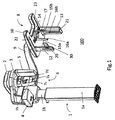
図1は、頭部計測撮像ユニットを含む、関連技術の口腔外歯科用撮像システムの斜視図を示す図である。図1に示されるように、典型的な口腔外歯科用撮像システム100は、支柱1を含む支持構造体を含む。柱1は、二次元または三次元で調整可能であってもよい。例えば、柱1は、伸縮式であることができ、下側部分1aの内側で摺動する上側部分1bを含み得る。水平な台2は、垂直な柱1によって支持されるかまたは保持されてもよく、回転可能なガントリ3を支持することができる。X線源4及び第1のX線撮像センサ5は、ガントリ3と、互いに対応して(例えば、反して、整合されて)取り付けられるかまたは結合されることができる。第1のX線センサ5は、パノラマ式(例えばスリット状の)センサ、またはコンピュータ断層撮影(例えば矩形、正方形形状の)センサであってもよい。好ましくは、X線源4に端を発するX線ビームは、第1の撮像領域、すなわち対象物または患者に放射された後、センサ5に当たる。第1の患者位置決め及び保持システム6は、第1の撮像領域の付近に、またはその中に動作可能に位置決めされることができる。例えば、第1の患者位置決め及び保持システム6は、X線源4と第1のX線撮像センサ5との間にあってもよい。第1の患者位置決め及び保持システム6は、前頭部支持部7aと、2つのハンドル7c及び7dを含むシールド7bとを含むことができる。そして、患者は、ハンドル7c及び7dを把持して、CTスキャンまたはパノラマスキャン中に静止したままにすることができる。
FIG. 1 is a perspective view of a related art extraoral dental imaging system including a head measurement imaging unit. As shown in FIG. 1, a typical extraoral
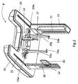
X線源4からさらに離隔した場合、頭部計測撮像ユニット8は、X線源4に対応させて保持され得る。例えば、図1に示されるように、頭部計測撮像ユニット8は、延伸した(例えば水平な)頭部計測アーム9を介して、垂直柱の上側部分1bに取り付けられるかまたは結合されることができる。頭部計測撮像ユニット8は、コリメータ12、第2のまたは頭部計測センサ13及び第2の患者位置決め及び保持システム14を支持する台10を含むことができる。図2においてさらに見られるように、第2の患者位置決め及び保持システム14は、前頭部支持部17と、各々が耳ロッド16a及び16bを支持する2つの一時的保持部材15a及び15bとを含むことができる。好ましくは、X線源4に端を発するX線ビームは、第2のまたは頭部計測撮像領域または患者に放射された後に、センサ13に当たる。第2の患者位置決め及び保持システム14は、第2の撮像領域の付近に、またはその中に動作可能に位置決めされることができる。例えば、第2の患者位置決め及び保持システム14のおかげで、患者はコリメータ12とセンサ13との間に、好ましくは第2の撮像領域の中に精密かつ繰り返し位置決めされる。保持部材15a及び15bのうち1つ以上は、それぞれレール15ar及び15brに沿って摺動することができ、それによって、2つの耳ロッド16a及び16b間の距離を、患者の頭部に適合するように変えることができる。前頭部支持部17もまた、調整可能であることができる。例えば、前頭部支持部17は、水平方向及び垂直方向に沿って摺動させることによって、少なくとも2つの直交する次元に調整可能であることができる。代替的に、前頭部支持部17は、三次元で、または3つ以上の直交軸を中心として調整可能であることができる。
When further separated from the X-ray source 4, the head
図2に示されるように、コリメータ12は、X線ビームを成形するための細長い開口またはスリット20を含むことができる。X線センサ13は、コリメータ12の垂直スリット20に(例えば、第2の撮像領域をわたって)面する細長い形状(例えば垂直スリット)を有する活性領域21を含むことができる。センサ13及びコリメータ12は、互いに面し、それによって、センサ13は、X線ビームがコリメータ12によって整形された後、かつX線ビームを放射された患者が、第2の患者の位置決め及び保持システム14上に位置決めされて保持された後に、X線源4に端を発するX線を受けることができるようにされる。患者の完全な頭蓋骨のスキャニングのために、コリメータ12は、レール22に沿ったX線スキャン中に動かすかまたは摺動することができ、センサ13は、レール23に沿って動かすかまたは摺動することができ、両方のレールは、台10に結合されている。例えば、レール22、23は、頭部計測撮像ユニット8の台10の下面に組み入れられることができる。頭部計測X線スキャン中の任意の時に、ソース(図示せず)の正面の一次コリメータと、コリメータ12のスリット20と、センサ13の活性領域との間の位置合わせがあってもよい。そのようなX線位置合わせは、例えば米国特許番号第5511106号に開示されている。頭部計測スキャン中の集合体の選択された位置において、センサ13によって、X線デジタル画像が得られる。頭部計測スキャンの終わりに、画像再構成装置(例えばハードウェア、ソフトウェア及び/または画像処理)は、頭部計測スキャン中に得られた複数の画像に基づいて、例えば当業者においては既知であるアルゴリズムを用いて、頭蓋骨全体の画像を再構成する。
As shown in FIG. 2, the
典型的な口腔外歯科用撮像システム100において良好な画質を可能にする正確な患者の位置決めのために、眼窩底及び外耳道を通過する直線を含有するフランクフルト平面は、水平でなければならない。フランクフルト平面が水平であることを制御するかまたは確認することを目的として、少なくとも部分的に透明な視覚的表示30を用いることができる。
For accurate patient positioning that allows good image quality in a typical extraoral
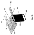
図3aは、脱係合された状態における、頭部計測台及び典型的な手位置決め装置の集合体の実施形態を示す図である。図3bは、係合された状態における、頭部計測台及び典型的な手位置決め装置の集合体の実施形態を示す図である。図3a〜3bに示されるように、典型的な手位置決め装置の実施形態は、図1に示された関連技術の口腔外歯科用撮像システムに適用されることができる。 FIG. 3a is a diagram showing an embodiment of an assembly of a head measurement platform and a typical hand positioning device in a disengaged state. FIG. 3b shows an embodiment of a head measurement platform and a typical hand positioning device assembly in an engaged state. As shown in FIGS. 3a-3b, an exemplary hand positioning device embodiment may be applied to the related art extraoral dental imaging system shown in FIG.
図3aに示されるように、手位置決め装置300は、X線に対して透過性であり、位置決め装置300が施術者によって把持されるかまたは簡単に操作されることができるようにする2つのハンドル303及び304を含むフレーム(例えばアルミニウム、金属、硬質材料、プラスチック等で作られる)に組み込まれるプレート302を含むことができる。ユーザによって把持されるための、他の既知の種類の領域または延伸部が想定されることができる。所定の形状を有する突起305は、位置決め装置300に固定されるかまたは一体化されることができる。図3aに示されるように、突起305は、円錐形状であることができ、ハンドルのうち一方、つまりハンドル304上に固定されることができる。頭部計測台110は、垂直に調整可能なベース(図示せず)に添着されることができる。2つのレール111及び112(台110の下側面上)は、それぞれX線ビームを成形するためのコリメータ(例えば、コリメータ12ではない)と、薄い矩形形状を有するX線頭部計測センサ(例えばセンサ13)との係合及び摺動を可能にすることができる。頭部計測X線画像は、頭部計測センサ及び頭部計測コリメータが同期移動して摺動する間に連続的に得られた患者の頭蓋骨または手のフレームの累積を含む、スキャニングプロセスを実行することによって得られる。図3a〜3bでは、台110のハウジング114は、患者の頭部位置決めユニット(図示せず)(例えばシステム14)の取り付けまたは固定専用であることができ、ハウジング113は、手位置決め装置300の突起305を係合するために設けられることができる。図3bは、ハウジング113内の突起305(例えば、所定の一致するまたは噛み合う形状を備える)によって係合された位置における、頭部計測台110及び手の位置決め装置300で構成された集合体を表す。
As shown in FIG. 3a, the
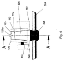
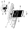
図4は、典型的な手位置決め装置の実施形態の、頭部計測台上での係合の拡大図を示す。図5は、図4の手位置決め装置の係合の、線A−A’に沿った断面図を示す。 FIG. 4 shows an enlarged view of the engagement on the head measurement platform of an exemplary hand positioning device embodiment. FIG. 5 shows a cross-sectional view of the engagement of the hand positioning device of FIG. 4 along line A-A '.
図4〜5に示されるように、頭部計測台110の表面150には、中空凹部の形状の中側面または穴を有するハウジング113を設けることができる。ハウジング113内の中空凹部の内側の形状は、先細状の円錐穴113aの全体形状を有することができる。一実施形態では、永久磁石123は、中空凹部または先細状の円錐穴113aの内部に位置決めされるかまたは固定される。図4に示されるように、永久磁石123は、先細状の円錐穴113aの内部に設けられた肩115(例えば底側表面)と、及び少なくとも1つの固定具(頂面または反対側の表面)との間に装着されることができる。図4〜5に示されるように、磁石123の頂面は、2つのねじ121a及び121bに抗して保持される。例えば、2つのねじ121a及び121bは、頂面120の正反対の位置に固定され、2つのリング122a及び122bを永久磁石123(例えば頂面)に対して押し付ける。また、磁石123は、肩115と2つのリング122a及び122bとの間に挟まれることができる。一実施形態では、永久磁石123の頂面は、先細状の円錐穴113aの円形の頂面120の上方にわずかに引き上げられる(例えば、越える)。一実施形態では、肩115は、わずかに先細状の円錐穴113aの中に延び、それによって、永久磁石123の大部分または実質的にすべてが、穴113aの中に露出するようにされる。代替的に、肩115は、永久磁石123の例えば20%、ほとんどまたはすべてを覆うことができる。加えて、磁石123をハウジング113内で装着する他の既知の方法を用いることができる。
As shown in FIGS. 4 to 5, on the
頭部計測台110内での手位置決め装置300の設置または係合位置において、手位置決め装置300の突起305は、ハウジング113の円錐穴113aの内側に貫通することができる。一実施形態では、突起305は、アルミニウムで作られ、手位置決め装置300のハンドル304上に固定されることができる。一定の典型的な実施形態では、突起305の外側面314は、穴113aの内面と嵌め合わせられるかまたは係合することができ、好ましくは、突起305の上面は、永久磁石123の下面と接触(または磁気係合)する。突起305には、突起305の対称軸に沿って延びる装着端331が設けられる。装着端331は、ねじ部331aを含むことができる。磁気部は、装着端331の内側であることができる。図5に示されるように、磁気ねじ330(例えば鉄ねじ)は、ねじ穴331に螺入されることができる。突起305が台10に装着されると、永久磁石123によって、磁気ねじ330に対して磁力が作用する。
The
有利には、突起305のねじ付き穴331の内側の磁気ねじ330の位置は、永久磁石123による磁力を変え、及び/または監視するために変更することができる。一方では、磁気ねじ330を、磁石123に十分に近接させて、磁力が手位置決め装置300全体の重量と平衡するようにしなければならない。磁石123によって台110における装着位置で保持されると、手位置決め装置300は、患者の手及び手根骨のX線撮像のために用いられるよう準備される。他方で、磁気ねじ330が磁石123にあまりにも近接して位置決めされると、吸引力が強力になりすぎる可能性があり、歯科医は、手位置決め装置300を頭部計測台110から(例えば、手根骨撮像プロセスの終わりにおいて)取り除くことが多少困難になる。さらに、吸引力の調整は、磁気ねじを、装着されたときに磁石123にさらに近接させるかまたはそれからさらに遠くになるように手動で動かす(例えば回したり、摺動させたりする)ことによって、手動で(または自動的に)行うことができる。一実施形態では、調整可能な吸引係合力は、被吸引部材と磁気アトラクタとの間の3D距離を増減することによって調整されることができる。例えば、磁気的に吸引可能な材料を突起305等に付加的に加えるかまたは取り除くことによる、吸引力を調整する代替の方法を想定することができる。有利には、本出願による典型的なシステム及び/または方法の実施形態は、従来技術の複雑でかさばる機構と比較して、手位置決め装置300を簡単に位置決めし、及び/または簡単に取り除くことを可能にすることができる。
Advantageously, the position of the
X線透過性のプレート302が、レール112に係合されたX線頭部計測センサ(表されないが、センサ13)に対して平行であり、それによって、手または手根骨の解剖学的構造に重なることなく、頭部計測センサの平面上に手が投影されるようにすることが最も重要である。この目的のために、本出願の一定の典型的な装置及び/または方法の実施形態は、手位置決め装置300の単一の装着方位及び/または正しい装着または設置の検知表示を提供する。
The
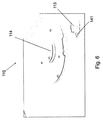
図6は、典型的な手位置決め装置実施形態の延伸部(例えばアーム)に正確な角度方位で係合するための凹部(例えばスリット)を表す、頭部計測台の拡大図を示す図である。一実施形態では、横棒340は、突起305から離れて直角に延びる(図4参照)。図6に示されるように、横棒340は、ハウジング113の穴113aに接合する(例えば、そこから延びる)頭部計測台110の表面150上に作られたスロット141に係合するように構成される。好ましくは、手位置決め装置300は、頭部計測台110の表面150上のハウジング113の穴113aに、単一の可能な角度位置で係合され、手位置決め装置300の表面302が、頭部計測センサの撮像平面に対して平行であることを確実にするようにすることができる。
FIG. 6 is an enlarged view of a head measurement table showing a recess (eg, a slit) for engaging the extension (eg, arm) of a typical hand positioning device embodiment with an accurate angular orientation. . In one embodiment, the
さらに、歯科医は、手位置決め装置300が頭部計測台110において好都合に位置決めされるかまたは正しく装着されたことを知らされる必要がある。この目的のために、一定の典型的なシステム及び/または方法の実施形態では、位置決め装置300の装着を検証するための表示器を、頭部計測台110または手位置決め装置300の内部に内蔵させることができる。一実施形態では、台110の表面150上の、ハウジング113の近傍に、電気スイッチ143が設けられる。電気スイッチ143は、スロット141(図4及び7参照)まで延びる接点を含むことができる。手位置決め装置300が台110に係合されると、導電性である横棒340は、電気スイッチ143の接点と接触し、その結果、手位置決め装置300の正確な係合を示すために、電流がスイッチ143を通って伝えられる。歯科医に対する対応情報は、コンピュータ画面のようなユーザインターフェース上に、または視覚的表示(例えば光、赤色/緑色等)を用いて表示されることができる。代替的に、歯科医に対する可聴警報または対応する情報が、スピーカのようなユーザインターフェースで放送されることができる。一実施形態では、横棒340は、少なくとも1つの絶縁性または非導電性コアを覆う金属または導電層であることができる。
In addition, the dentist needs to be informed that the
本出願の典型的な実施形態と一致させて、コンピュータプログラムは、電子メモリからアクセスされる画像データに対して行う記憶された命令を利用する。画像処理分野における当業者には理解されるように、本出願の典型的な実施形態における撮像システムを動作させるためのコンピュータプログラムは、好適な汎用コンピュータシステム、例えばパーソナルコンピュータまたはワークステーションによって利用されることができる。しかしながら、多くの他のタイプのコンピュータシステムを用いて、本出願のコンピュータプログラムを実行することができ、例えば、ネットワーク接続されたプロセッサの機構を含む。本出願の典型的な方法/装置を行うためのコンピュータプログラムは、コンピュータ可読記憶媒体に記憶されてもよい。本媒体は、例えばハードドライブ等の磁気ディスク、またはリムーバブル装置もしくは磁気テープ等の磁気記憶部媒体、光学ディスク、光学テープ、または機械可読光学符号化等の光学記憶部媒体、ランダムアクセスメモリ(RAM)、またはリードオンリーメモリ(ROM)等のソリッドステート電子記憶装置、またはコンピュータプログラムを記憶するために使用される任意の他の物理的装置または媒体を含み得る。また、本出願の典型的な方法/装置を行うためのコンピュータプログラムは、インターネットまたは他のネットワークもしくは通信媒体を経由して画像プロセッサに接続されたコンピュータ可読記憶媒体上に記憶されてもよい。また、当業者においては、そのようなコンピュータプログラム製品の等価物が、ハードウェアにおいて構築されてもよいことがさらに容易に認識されよう。 Consistent with exemplary embodiments of the present application, a computer program utilizes stored instructions that are performed on image data accessed from electronic memory. As will be appreciated by those skilled in the image processing art, the computer program for operating the imaging system in the exemplary embodiments of the present application is utilized by a suitable general purpose computer system, such as a personal computer or workstation. be able to. However, many other types of computer systems can be used to execute the computer program of the present application, including, for example, a networked processor mechanism. A computer program for performing the exemplary methods / apparatus of the present application may be stored on a computer readable storage medium. This medium can be, for example, a magnetic disk such as a hard drive, a magnetic storage medium such as a removable device or a magnetic tape, an optical storage medium such as an optical disk, an optical tape, or a machine-readable optical encoding, or a random access memory (RAM). Or a solid state electronic storage device such as a read only memory (ROM), or any other physical device or medium used to store a computer program. A computer program for performing the exemplary method / apparatus of the present application may also be stored on a computer-readable storage medium connected to the image processor via the Internet or other network or communication medium. Those skilled in the art will also readily recognize that equivalents of such computer program products may be constructed in hardware.
用語「memory(メモリ)」は、本開示の文脈では「コンピュータアクセス可能メモリ」に相当し、画像データを記憶してそれに対する作業を行うために用いられ、例えばデータベースを含むコンピュータシステムにアクセス可能である、任意のタイプの一時的またはより永続的なデータ記憶作業域を指すことができることに留意すべきである。メモリは、例えば磁気または光学記憶部等の長期記憶媒体を用いる、不揮発性のものであることができる。代わりに、メモリは、マイクロプロセッサまたは他の制御論理プロセッサ装置によって、一時的バッファまたは作業域として用いられるランダムアクセスメモリ(RAM)等の電子回路を用いる、より揮発性の性質であることができる。通常、表示データは、例えば表示装置に直接関連付けられた一時記憶バッファに記憶され、表示データを提供するために、必要に応じて周期的に更新される。また、この一時記憶部バッファは、当該用語が本開示において用いられる場合、メモリの1タイプとして考慮される。また、メモリは、演算及び他の処理を実行して、中間及び最終結果を記憶するためのデータ作業域としても用いられる。コンピュータアクセス可能メモリは、揮発性、不揮発性、または揮発性及び不揮発性タイプのハイブリッドな組み合わせであることができる。 The term “memory” corresponds to “computer-accessible memory” in the context of this disclosure, and is used to store and work with image data, eg, accessible to a computer system including a database. It should be noted that any type of temporary or more permanent data storage work area can be referred to. The memory can be non-volatile using a long-term storage medium such as a magnetic or optical storage unit. Alternatively, the memory can be of a more volatile nature, using electronic circuitry such as random access memory (RAM) that is used as a temporary buffer or work area by a microprocessor or other control logic processor device. Typically, display data is stored, for example, in a temporary storage buffer that is directly associated with the display device and is periodically updated as needed to provide display data. This temporary storage buffer is also considered a type of memory when the term is used in this disclosure. The memory is also used as a data work area for performing calculations and other processing to store intermediate and final results. Computer accessible memory can be volatile, non-volatile, or a hybrid combination of volatile and non-volatile types.
本出願のコンピュータプログラム製品は、周知であるさまざまな画像操作アルゴリズム及びプロセスを活用してもよいことが理解されよう。本出願の実施形態のコンピュータプログラム製品は、実施態様のために有用な、本明細書で特に示されていないかまたは説明されていないアルゴリズム及びプロセスを組み入れ得ることがさらに理解されよう。そのようなアルゴリズム及びプロセスは、当業者の画像処理技術の範囲内である従来のユーティリティを含んでもよい。画像を作成するかそうでなければ処理するための、または本出願のコンピュータプログラム製品と協働するためのそのようなアルゴリズム及びシステム、及びハードウェア及び/またはソフトウェアの付加的な態様は、本明細書では特に示されていないかまたは説明されておらず、当技術分野において既知であるそのようなアルゴリズム、システム、ハードウェア、構成要素及び要素から選択され得る。 It will be appreciated that the computer program product of the present application may utilize a variety of well-known image manipulation algorithms and processes. It will be further appreciated that the computer program product of the embodiments of the present application may incorporate algorithms and processes not specifically shown or described herein that are useful for the implementation. Such algorithms and processes may include conventional utilities that are within the scope of image processing techniques of those skilled in the art. Additional aspects of such algorithms and systems and hardware and / or software for creating or otherwise processing images or for cooperating with the computer program products of the present application are described herein. It may be selected from such algorithms, systems, hardware, components and elements not specifically shown or described in the document and known in the art.
一定の典型的な実施形態では、第1の患者位置決め及び保持システム6は、台2または回転可能なガントリ3から吊設された実質的に透過性のシールドと、下顎受けと噛み要素とを含む下顎位置決め要素とを含むことができる。一実施形態では、シールドは、下顎支持部と前頭部支持部との間に配設された開放窓を含むことができる。一実施形態では、シールドは、目視可能な程度に透過性であることができ、X線を含むさらなる放射に対して透過性であることができ、及び/またはポリカーボネート成形体材料から形成されることができる。一実施形態では、下顎支持部は、噛み要素のための高さアジャスタを含むことができ、前頭部支持部は、患者に向かって調整可能に旋回可能であるように構成される。一実施形態では、シールドは、シールド上に、またはシールドに結合された別個のパネル上に装着された台のための柱高さ調整を設定するための、1つ以上の制御部を含むことができる。一実施形態では、シールドは、患者の位置決めを支援するための1つ以上のマーキングを含むことができる。一実施形態では、シールドは、第1のフランクフルト平面位置決め表示器を含むことができる。
In certain exemplary embodiments, the first patient positioning and retention system 6 includes a substantially permeable shield suspended from the
一定の典型的な実施形態では、口腔外撮像システムは、少なくとも1つの寸法に調整可能な支持台と、支持台に装着され、X線源及び撮像センサパネルを、撮像領域を中心、として周回させるように構成された第1の台と、口腔外撮像システムに結合され、X線源と第1のセンサとの間に位置決めされて、それによって、X線が、第1の患者位置決めユニットに結合され、下顎位置決め要素を含む下顎支持部を含む撮像領域に放射された後に第1のセンサに当たるようにされる、第1の患者位置決めユニットと、第1の患者位置決めユニットシールドに結合された頭部支持部と、第1のフランクフルト平面位置決め表示器と、支持台に装着され、第2の撮像センサパネルを第2の撮像領域の周りに位置決めするように構成された第2の台と、第2の台に結合され、X線源と第2のセンサとの間に位置決めされて、それによって、X線が、第2の患者位置決めユニットに結合された頭部支持部を含む第2の撮像領域に放射された後に第2のセンサに当たるようにされる、第2の患者位置決めユニットと、第2のフランクフルト平面位置決め表示器とを含むことができる。一実施形態では、第2のフランクフルト平面位置決め表示器は、固定して装着されるか、着脱可能に装着されるか、または少なくとも2つの位置間で動くように装着されるか、もしくは回転可能に装着される。一実施形態では、第2の患者位置決めユニットは、X線源と第2の撮像センサパネルとの間に患者を繰り返しかつ正確に位置決めするように構成される。 In certain exemplary embodiments, the extraoral imaging system is mounted on the support base that is adjustable to at least one dimension, and circulates the X-ray source and the imaging sensor panel about the imaging area. Coupled to an extraoral imaging system and positioned between an X-ray source and a first sensor, whereby X-rays are coupled to a first patient positioning unit A head coupled to the first patient positioning unit and the first patient positioning unit shield, wherein the head is adapted to strike the first sensor after being emitted to the imaging region including the lower jaw support including the lower jaw positioning element A support, a first Frankfurt planar positioning indicator, a second base mounted on the support base and configured to position the second imaging sensor panel around the second imaging region; A second imaging coupled to the two pedestals and positioned between the x-ray source and the second sensor, whereby the x-ray is coupled to the second patient positioning unit. A second patient positioning unit adapted to strike the second sensor after being emitted to the area and a second Frankfurt planar positioning indicator can be included. In one embodiment, the second Frankfurt planar positioning indicator is fixedly mounted, removably mounted, or mounted to move between at least two positions, or rotatable. Installed. In one embodiment, the second patient positioning unit is configured to repeatedly and accurately position the patient between the x-ray source and the second imaging sensor panel.
本発明は詳細に説明され、そして典型的または今のところ好ましい実施形態を特に参照して説明されてきたかもしれないが、本発明の本質及び範囲内で、変形及び改変がなされることができることが理解されよう。例えば、本明細書に開示された典型的な手位置決め装置の実施形態は、頭部計測台に装着するための単一のアームと単一の方向への移動とを用いる。代替的に、典型的な手位置決め装置の実施形態は、選択された方位(例えば器具なし)と、例えば重力と、所定の位置合わせを保持するための切り欠き位置とをもって、頭部計測台内部へ設置するための直角方向への2つまたは二重の移動を用いることができる。さらに、一定の選択された実施形態では、手位置決め装置は、第1の方向に沿って延びるように向けられた装着凹部及び細長凹部を含むことができ、頭部計測台は、延伸部を備え、手位置決め装置は、延伸部が第1の方向で位置合わせされたときのみ、頭部計測台に装着されることができる。加えて、本出願による典型的な装置及び/または方法の実施形態は、複合型の頭部計測パノラマ式及びコンピュータ断層撮影歯科用撮像装置に関して説明されてきたが、任意の付加的な動作モードまたは機能性をもって、スタンドアロンの頭部計測撮像装置または頭部計測撮像装置に適用可能であることが意図される。したがって、現在開示されている典型的な実施形態は、すべての点において、例示的であり限定的ではないと見なされる。また、磁力を用いることに代わるものを想定することもできる。本発明の範囲は、添付の請求項によって示され、その等価物の意味合い及び範囲内でもたらされるすべての変化は、その中に包含されることが意図される。 Although the present invention has been described in detail and may have been described with particular reference to exemplary or presently preferred embodiments, variations and modifications can be made within the spirit and scope of the invention. Will be understood. For example, the exemplary hand positioning device embodiments disclosed herein use a single arm and movement in a single direction for mounting on a head measurement platform. Alternatively, typical hand positioning device embodiments have a selected orientation (e.g., no instrument), e.g., gravity, and a notch position to hold a predetermined alignment, within the head measurement platform. Two or double movements in the right-angle direction for installation can be used. Further, in certain selected embodiments, the hand positioning device can include a mounting recess and an elongated recess oriented to extend along the first direction, and the head measurement platform comprises an extension. The hand positioning device can be attached to the head measurement table only when the extending portion is aligned in the first direction. In addition, exemplary apparatus and / or method embodiments according to the present application have been described with respect to combined cephalometric panoramic and computed tomography dental imaging devices, but any additional modes of operation or It is intended to be applicable to a stand-alone head measurement imaging device or a head measurement imaging device with functionality. Accordingly, the presently disclosed exemplary embodiments are considered in all respects as illustrative and not restrictive. An alternative to using magnetic force can also be assumed. The scope of the invention is indicated by the appended claims, and all changes that come within the meaning and range of equivalents are intended to be embraced therein.
1つ以上の実施態様に対して本発明を例証してきたが、添付の請求項の本質及び範囲から逸脱することなく、例証された例に対する代替及び/または改変がなされてもよい。加えて、本発明の特定の特徴は、いくつかの実施態様のうち1つに対して開示されている可能性があるが、そのような特徴は、その他の実施態様の1つ以上他の特徴と組み合わせられることができ、任意の所与のまたは特定の機能に対して所望され、かつそれにとって有利であることができる。用語「at least one of(のうち少なくとも1つ)」は、列記された項目のうち1つ以上を選択することができることを意味するために用いられる。用語「about(およそ)」は、例証された実施形態に対してプロセスまたは構造において不適合とならない限り、列記された値をある程度変更することができることを示す。最後に、「exemplary(典型的な)」は、説明が一実施例として用いられ、それが理想であることを含意するものではないことを示す。当業者においては、本発明の他の実施形態は、本明細書を考慮し、本明細書に開示された本発明を実践することから明白となろう。本明細書及び実施例は、例示としてのみ考慮されることが意図され、本発明の真の範囲及び本質は、以下の請求項によって示され、その等価物の意味合い及び範囲内でもたらされるすべての変化は、その中に包含されることが意図される。 Although the invention has been illustrated with respect to one or more embodiments, alternatives and / or modifications to the illustrated examples may be made without departing from the spirit and scope of the appended claims. In addition, although certain features of the invention may be disclosed for one of several embodiments, such features may include one or more other features of other embodiments. Can be combined with and can be desired and advantageous for any given or specific function. The term “at least one of” is used to mean that one or more of the listed items can be selected. The term “about” indicates that the listed values can be modified to some extent as long as the process or structure is not incompatible with the illustrated embodiment. Finally, “exemplary” indicates that the description is used as an example and does not imply that it is ideal. Other embodiments of the invention will be apparent to those skilled in the art from consideration of the specification and practice of the invention disclosed herein. It is intended that the specification and examples be considered as exemplary only, with a true scope and nature of the invention being indicated by the following claims, all coming within the meaning and range of equivalents thereof Changes are intended to be encompassed therein.
Claims (15)
前記支持台に結合され、頭部計測撮像センサを、X線源によって形成された第1の撮像領域の近くに位置決めするように構成された頭部計測モジュールであって、前記X線源からのX線が、前記第1の撮像領域に放射された後に前記頭部計測センサに衝突する、頭部計測モジュールと、
前記第1の撮像領域付近に動作可能に位置決めされた頭部計測患者位置決めユニットと、
頭部計測コリメータと、
前記コリメータと前記頭部計測センサとの間で、前記頭部計測モジュールに着脱可能に結合された手位置決め装置であって、前記手位置決め装置が、前記手位置決め装置に対して単一の方向に力を付与することによって取り除かれる、手位置決め装置と、
を備える、口腔外撮像システム。 A support that is adjustable in at least one dimension;
A head measurement module coupled to the support and configured to position a head measurement imaging sensor near a first imaging region formed by an X-ray source, from the X-ray source A head measurement module that collides with the head measurement sensor after X-rays are emitted to the first imaging region;
A head measurement patient positioning unit operably positioned near the first imaging region;
A head measurement collimator;
A hand positioning device detachably coupled to the head measuring module between the collimator and the head measuring sensor, wherein the hand positioning device is in a single direction with respect to the hand positioning device. A hand positioning device that is removed by applying force;
An extraoral imaging system.
少なくとも2つの次元において調整可能な前頭部支持部と、
少なくとも1つの次元において調整可能な、少なくとも1つの一時的保持部材と、
前記一体型頭部計測コリメータの一側または両側に装着される、引き込み式頭部計測フランクフルト平面位置決め表示器と、
を備える、請求項1に記載の口腔外撮像システム。 The head measurement patient positioning unit is between the integrated head measurement collimator and the head measurement imaging sensor, and the head measurement patient positioning unit is
A forehead support adjustable in at least two dimensions;
At least one temporary holding member adjustable in at least one dimension;
Retractable head measurement Frankfurt plane positioning indicator mounted on one or both sides of the integrated head measurement collimator;
The extraoral imaging system according to claim 1, comprising:
前記口腔外撮像システムに結合され、前記第2の撮像領域付近に動作可能に位置決めされた第2の患者位置決めユニットであって、
ハンドルを備える細長シールドと、
前記細長シールドに結合され、下顎位置決め要素を備える下顎支持部と、
前記細長シールドに結合された頭部支持部と、を備える、第2の患者位置決めユニットと、
第2のフランクフルト平面位置決め表示器と、
を備える、請求項1に記載の口腔外撮像システム。 The X-ray source and the imaging sensor mounted on the support base are configured to circulate around the second imaging region, whereby the X-rays are emitted to the second imaging region and then A first platform adapted to strike the imaging sensor;
A second patient positioning unit coupled to the extraoral imaging system and operatively positioned near the second imaging region;
An elongated shield with a handle;
A lower jaw support coupled to the elongated shield and comprising a lower jaw positioning element;
A second patient positioning unit comprising: a head support coupled to the elongated shield;
A second Frankfurt plane positioning indicator;
The extraoral imaging system according to claim 1, comprising:
Applications Claiming Priority (3)
| Application Number | Priority Date | Filing Date | Title |
|---|---|---|---|
| US201462087374P | 2014-12-04 | 2014-12-04 | |
| US62/087,374 | 2014-12-04 | ||
| PCT/IB2015/000339 WO2016087911A1 (en) | 2014-12-04 | 2015-01-14 | Hand positioner for cephalometric extra oral dental imaging devices |
Publications (2)
| Publication Number | Publication Date |
|---|---|
| JP2017536203A true JP2017536203A (en) | 2017-12-07 |
| JP2017536203A5 JP2017536203A5 (en) | 2018-01-25 |
Family
ID=52823699
Family Applications (1)
| Application Number | Title | Priority Date | Filing Date |
|---|---|---|---|
| JP2017529710A Pending JP2017536203A (en) | 2014-12-04 | 2015-01-14 | Hand positioning device for extraoral dental imaging device for head measurement |
Country Status (5)
| Country | Link |
|---|---|
| US (1) | US10485495B2 (en) |
| EP (1) | EP3226771B1 (en) |
| JP (1) | JP2017536203A (en) |
| KR (1) | KR20170089873A (en) |
| WO (1) | WO2016087911A1 (en) |
Families Citing this family (3)
| Publication number | Priority date | Publication date | Assignee | Title |
|---|---|---|---|---|
| WO2016087911A1 (en) | 2014-12-04 | 2016-06-09 | Trophy | Hand positioner for cephalometric extra oral dental imaging devices |
| EP3625538A4 (en) * | 2017-11-27 | 2021-02-17 | Leica Biosystems Imaging, Inc. | Slide rack determination system |
| US11000256B2 (en) * | 2018-11-09 | 2021-05-11 | Palodex Group Oy | Calibrating an X-ray medical imaging device for cephalometric imaging |
Citations (2)
| Publication number | Priority date | Publication date | Assignee | Title |
|---|---|---|---|---|
| JP2011019688A (en) * | 2009-07-15 | 2011-02-03 | Asahi Roentgen Kogyo Kk | Head part standard fixing device for x-ray radiography |
| US20110142197A1 (en) * | 2009-12-15 | 2011-06-16 | Midmark Corporation | Patient positioning system for panoramic dental radiation imaging system |
Family Cites Families (8)
| Publication number | Priority date | Publication date | Assignee | Title |
|---|---|---|---|---|
| EP0632995B1 (en) | 1993-07-06 | 1999-04-21 | Sirona Dental Systems GmbH & Co.KG | Dental X-ray diagnostic device |
| AU2002358458A1 (en) | 2001-12-10 | 2003-06-23 | Osteomate Aps | Method and apparatus for establishing an osteoporosis measure |
| US20090196395A1 (en) * | 2008-06-20 | 2009-08-06 | Gendex Corporation | Cephalometric x-ray imaging apparatus |
| US9125611B2 (en) | 2010-12-13 | 2015-09-08 | Orthoscan, Inc. | Mobile fluoroscopic imaging system |
| ITBO20110765A1 (en) | 2011-12-28 | 2013-06-29 | Cefla Coop | APPARATUS FOR DENTAL RADIOGRAPHY WITH IMPROVED ACCURACY |
| ITMI20120099A1 (en) | 2012-01-27 | 2013-07-28 | Gotzen S R L De | APPARATUS AND METHOD FOR DIGITAL RADIOGRAPHY |
| WO2016087911A1 (en) | 2014-12-04 | 2016-06-09 | Trophy | Hand positioner for cephalometric extra oral dental imaging devices |
| CN107852508A (en) | 2015-07-31 | 2018-03-27 | 深圳市大疆创新科技有限公司 | The method for changing region of search |
-
2015
- 2015-01-14 WO PCT/IB2015/000339 patent/WO2016087911A1/en active Application Filing
- 2015-01-14 JP JP2017529710A patent/JP2017536203A/en active Pending
- 2015-01-14 KR KR1020177015005A patent/KR20170089873A/en not_active Application Discontinuation
- 2015-01-14 EP EP15715402.2A patent/EP3226771B1/en active Active
- 2015-01-14 US US15/524,767 patent/US10485495B2/en active Active
Patent Citations (2)
| Publication number | Priority date | Publication date | Assignee | Title |
|---|---|---|---|---|
| JP2011019688A (en) * | 2009-07-15 | 2011-02-03 | Asahi Roentgen Kogyo Kk | Head part standard fixing device for x-ray radiography |
| US20110142197A1 (en) * | 2009-12-15 | 2011-06-16 | Midmark Corporation | Patient positioning system for panoramic dental radiation imaging system |
Also Published As
| Publication number | Publication date |
|---|---|
| EP3226771A1 (en) | 2017-10-11 |
| US20170325760A1 (en) | 2017-11-16 |
| KR20170089873A (en) | 2017-08-04 |
| US10485495B2 (en) | 2019-11-26 |
| WO2016087911A1 (en) | 2016-06-09 |
| EP3226771B1 (en) | 2018-12-12 |
Similar Documents
| Publication | Publication Date | Title |
|---|---|---|
| JP6297504B2 (en) | Apparatus and method for digital radiography | |
| US20210338180A1 (en) | Stationary intraoral tomosynthesis imaging systems, methods, and computer readable media for three dimensional dental imaging | |
| JP7382042B2 (en) | Fixed intraoral tomosynthesis imaging system, method, and computer-readable medium for three-dimensional dental imaging | |
| US11701071B2 (en) | Dental bite block for 2D imaging | |
| US10441227B2 (en) | Cephalostat | |
| JP2017536203A (en) | Hand positioning device for extraoral dental imaging device for head measurement | |
| US11045157B2 (en) | Visual indicator for the assessment of the tilt of the Frankfort plane in extra oral dental imaging devices | |
| JP6448790B2 (en) | Collimator for extraoral dental imaging device for head measurement | |
| EP3261543B1 (en) | Bite block for cbct imaging device | |
| Solow et al. | A cephalometric unit for research and hospital environments | |
| US20170332985A1 (en) | Cephalometric patient positioning unit extra oral dental imaging devices |
Legal Events
| Date | Code | Title | Description |
|---|---|---|---|
| A521 | Request for written amendment filed |
Free format text: JAPANESE INTERMEDIATE CODE: A523 Effective date: 20171201 |
|
| A621 | Written request for application examination |
Free format text: JAPANESE INTERMEDIATE CODE: A621 Effective date: 20171201 |
|
| A977 | Report on retrieval |
Free format text: JAPANESE INTERMEDIATE CODE: A971007 Effective date: 20180731 |
|
| A131 | Notification of reasons for refusal |
Free format text: JAPANESE INTERMEDIATE CODE: A131 Effective date: 20180828 |
|
| A02 | Decision of refusal |
Free format text: JAPANESE INTERMEDIATE CODE: A02 Effective date: 20190326 |