EP0632905B1 - Methods and means for reducing temperature-induced variations in lenses and lens devices - Google Patents
Methods and means for reducing temperature-induced variations in lenses and lens devices Download PDFInfo
- Publication number
- EP0632905B1 EP0632905B1 EP93905053A EP93905053A EP0632905B1 EP 0632905 B1 EP0632905 B1 EP 0632905B1 EP 93905053 A EP93905053 A EP 93905053A EP 93905053 A EP93905053 A EP 93905053A EP 0632905 B1 EP0632905 B1 EP 0632905B1
- Authority
- EP
- European Patent Office
- Prior art keywords
- lens
- kinoform
- power
- temperature
- changes
- Prior art date
- Legal status (The legal status is an assumption and is not a legal conclusion. Google has not performed a legal analysis and makes no representation as to the accuracy of the status listed.)
- Revoked
Links
- 238000000034 method Methods 0.000 title claims description 5
- 239000000463 material Substances 0.000 claims description 38
- 230000003287 optical effect Effects 0.000 claims description 30
- 230000008859 change Effects 0.000 claims description 28
- 230000004075 alteration Effects 0.000 claims description 25
- 125000006850 spacer group Chemical group 0.000 claims description 14
- 230000004044 response Effects 0.000 claims description 9
- 238000004519 manufacturing process Methods 0.000 claims description 4
- 230000001747 exhibiting effect Effects 0.000 claims description 2
- 239000012780 transparent material Substances 0.000 claims 1
- 229920003229 poly(methyl methacrylate) Polymers 0.000 description 12
- 239000004926 polymethyl methacrylate Substances 0.000 description 12
- 230000000694 effects Effects 0.000 description 7
- 229920003023 plastic Polymers 0.000 description 7
- 239000004033 plastic Substances 0.000 description 7
- 238000013461 design Methods 0.000 description 5
- 239000011521 glass Substances 0.000 description 5
- 235000003913 Coccoloba uvifera Nutrition 0.000 description 4
- 240000008976 Pterocarpus marsupium Species 0.000 description 4
- 238000013459 approach Methods 0.000 description 3
- 239000013590 bulk material Substances 0.000 description 3
- 239000002131 composite material Substances 0.000 description 3
- 238000012937 correction Methods 0.000 description 3
- 210000001747 pupil Anatomy 0.000 description 3
- 238000004364 calculation method Methods 0.000 description 2
- 230000007423 decrease Effects 0.000 description 2
- 238000009795 derivation Methods 0.000 description 2
- 238000007516 diamond turning Methods 0.000 description 2
- 229910052732 germanium Inorganic materials 0.000 description 2
- GNPVGFCGXDBREM-UHFFFAOYSA-N germanium atom Chemical compound [Ge] GNPVGFCGXDBREM-UHFFFAOYSA-N 0.000 description 2
- 238000005259 measurement Methods 0.000 description 2
- 230000006903 response to temperature Effects 0.000 description 2
- 241000961787 Josa Species 0.000 description 1
- 229920004142 LEXAN™ Polymers 0.000 description 1
- 239000004418 Lexan Substances 0.000 description 1
- 238000010521 absorption reaction Methods 0.000 description 1
- 239000000109 continuous material Substances 0.000 description 1
- 230000001419 dependent effect Effects 0.000 description 1
- 238000011161 development Methods 0.000 description 1
- 229910003460 diamond Inorganic materials 0.000 description 1
- 239000010432 diamond Substances 0.000 description 1
- -1 i.e. Substances 0.000 description 1
- 238000003754 machining Methods 0.000 description 1
- 238000012986 modification Methods 0.000 description 1
- 230000004048 modification Effects 0.000 description 1
- 230000009467 reduction Effects 0.000 description 1
- 238000011160 research Methods 0.000 description 1
- 239000011347 resin Substances 0.000 description 1
- 229920005989 resin Polymers 0.000 description 1
- 230000002277 temperature effect Effects 0.000 description 1
- PGAPATLGJSQQBU-UHFFFAOYSA-M thallium(i) bromide Chemical compound [Tl]Br PGAPATLGJSQQBU-UHFFFAOYSA-M 0.000 description 1
- 239000002023 wood Substances 0.000 description 1
Images


Classifications
-
- G—PHYSICS
- G02—OPTICS
- G02B—OPTICAL ELEMENTS, SYSTEMS OR APPARATUS
- G02B5/00—Optical elements other than lenses
- G02B5/18—Diffraction gratings
-
- G—PHYSICS
- G02—OPTICS
- G02B—OPTICAL ELEMENTS, SYSTEMS OR APPARATUS
- G02B27/00—Optical systems or apparatus not provided for by any of the groups G02B1/00 - G02B26/00, G02B30/00
- G02B27/0025—Optical systems or apparatus not provided for by any of the groups G02B1/00 - G02B26/00, G02B30/00 for optical correction, e.g. distorsion, aberration
-
- G—PHYSICS
- G02—OPTICS
- G02B—OPTICAL ELEMENTS, SYSTEMS OR APPARATUS
- G02B5/00—Optical elements other than lenses
- G02B5/18—Diffraction gratings
- G02B5/1876—Diffractive Fresnel lenses; Zone plates; Kinoforms
-
- G—PHYSICS
- G02—OPTICS
- G02B—OPTICAL ELEMENTS, SYSTEMS OR APPARATUS
- G02B5/00—Optical elements other than lenses
- G02B5/18—Diffraction gratings
- G02B5/1876—Diffractive Fresnel lenses; Zone plates; Kinoforms
- G02B5/189—Structurally combined with optical elements not having diffractive power
- G02B5/1895—Structurally combined with optical elements not having diffractive power such optical elements having dioptric power
Definitions
- This invention relates primarily to lenses composed of a single material and to systems employing such lenses. More particularly, it relates to designs for such lenses which, when used singly or as part of a system, have the property that certain of their optical characteristics remain relatively unchanged with changes in temperature or change in a controlled predetermined way.
- correction of lens aberrations normally requires the use of multiple component lenses even when thermal effects are not a dominant factor.
- chromatic aberrations have been corrected by using a single element lens with a conventional refractive or "bulk" portion, and a shallow surface diffractive portion.
- the diffractive portion reduces the chromatic aberrations introduced by the bulk portion.
- Such compensation may be important, for example, in arrangements used to focus laser beams onto the surfaces of compact disks.
- An aspherical optical lens incorporating a kinoform for correcting spherical aberration of spherical glass lenses is known from JP-A-4-016 910.
- the kinoform therein is formed on the spherical glass lens by separately applying a coat of an optically transparent resin to one of the lens surfaces and thus requires a multi-step manufacturing process.
- Another object of the invention is to provide a single-material lens with selected optical characteristics that vary with temperature in a selected manner, for example, in a manner which maintains an optical characteristic substantially constant at a given wavelength.
- Another object is to supply an athermalized single-material lens with substantially constant focal length, spherical aberration correction, or any combination of these.
- Yet another object of the invention is to provide a single-material lens that compensates not only for temperature-induced optical variations of the lens itself but also the temperature-induced variations in the structure spacing the lens from an object or a sensor at or near a specific dominant wavelength.
- the invention also concerns a method of manufacturing a lens according to claim 12.
- the invention is based upon the recognition that a kinoform produces a temperature-induced optical response different from that of the bulk material in which it may be formed and that the kinoform's temperature-induced optical response can be used opposition to that of a refractive lens formed of the bulk material, even in cases where kinoform is itself formed of the same material.
- a lens comprised of a single optical material has a refractive or bulk portion having a given optical characteristic at one dominant wavelength that shifts in one sense in response to a temperature change and includes a "kinoform", or diffractive portion that responds to the same temperature change at the same wavelength by shifting the lens characteristics in a sense opposite to that of the bulk portion and in a predetermined selected manner.
- the kinoform shifts the lens characteristic in an amount sufficient to compensate for the temperature change in the bulk portion.
- the lens forms part of a lens arrangement which includes spacers for spacing it from a target such as an object or a film, and the kinoform compensation offsets not only the temperature induced shifts in the bulk portion but in the spacing as well.
- the compensation counteracts the effect of temperature changes in back focal length at a dominant wavelength; and, according to yet another feature, it offsets the effects of temperature changes on spherical aberrations.
- the kinoform power is normally greater than the bulk refractive power.
- Figures 1 and 2 illustrate a hybrid lens 10 composed of a single plastic material.
- the material is a plastic known as polymethylmethacrylate (PMMA).
- Lens 10 comprises a negative refractive surface 14 on one side and a generally convex composite surface which one may consider as composed of a base positive refractive surface 16 and a kinoform 20.
- Kinoform 20 includes annular grooves, 22 having typical outer profiles 24 and inner rises 26.
- the underlying base shown as surface 16 extends along the valleys of annular grooves 22.
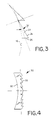
- the profiles 24 form angles ⁇ measured from a line parallel to surface 16 at the apex of each groove 22 as shown in Figure 3.
- the underlying refractive surface 16 and the refractive surface 14, together with the material between them define a bulk refractive lens or lens portion. Depending on the refractive index of the material, this lens portion exhibits a bulk power, ⁇ B , quite apart from kinoform 20. The distances between adjacent valleys or peaks in the kinoform 20 determine the power of the kinoform.
- the profiles 24 are shaped to maximize the amount of light that goes into a selected diffraction order of kinoform 20. Obviously, it will be appreciated that the scale of the feature of lens 10, and others shown subsequently, have been greatly exaggerated for clarity in illustrating principles.
- a kinoform is a diffractive wavefront reconstruction device as described, for example, by L.B. Lesem, P.M. Hirsch, and J.A. Jordan, Jr. in the IBM Journal of Research Development, pp 150-155, (1969).
- Kinoforms may be considered as phase matched Fresnel lenses with phase steps of 2 K ⁇ where K is an integer designating the diffraction order, i.e., the height of rise 26.
- K is an integer designating the diffraction order, i.e., the height of rise 26.
- they combine properties of a classic Fresnel lens, O.E. Miller, J.H. McLeod and W.T. Sherwood, "Thin Sheet Plastic Frensel Lenses of High Aperture", (JOSA Vol, No. 1, pp 807-815, Nov.
- the term refers to phase-only surface-relief lenses that can be made to be nearly 100% efficient for a given wavelength and order by designing the geometry of each groove through choice of the shape and depth of each peak and valley, neglecting absorption.
- Temperature induced changes in the optical characteristics, for example, in this case back focal length at a given wavelength, of the bulk portion lens 10 occur at a rate different from changes in the same characteristics, over the same temperature changes, in kinoform 20.
- kinoform 20 exhibits temperature induced focal length changes of a sign opposite to that of the refractive bulk portion.
- the bulk lens, with its refractive surface 14 and surface 16, and the kinoform 20 focus collimated rays of light 38 onto a focal point 40 at a back focal length 42 from the vertex of the kinoform 20, shown designated at 44.
- Thermally induced changes in the index of refraction and the geometry of the bulk lens bounded by the refractive surfaces 14 and 16 would ordinarily change back focal length 42 of lens 10 for any predetermined wavelength, such as 815 nm.
- kinoform 20 offsets such temperature-induced changes in the index of refraction and the geometry of the bulk lens for a predetermined wavelength. This results in a substantially temperature-independent, i.e., athermalized, back focus for lens 10 at the predetermined wavelength.
- the athermalization may occur exactly at chosen temperatures and vary slightly between the temperatures. On a practical basis, one can consider it as covering a given temperature range.
- the material of lens 10, including the bulk lens and kinoform 20 is a continuous material, i.e., PMMA.
- Available handbooks such as the Photonics Handbook, published in 1991 (T.C. Laurin, Pittsfield, MA) pages H-302 and H-304, contain information about the material response to temperature. The same handbook permits determination of the power of kinoform 20, and one can select the kinoform power to be opposite in sign from the power of the underlying bulk lens.
- the total power of the lens 10, considered as a thin lens is equal to the power ⁇ B of the bulk lens plus the power ⁇ K of kinoform 20.
- ⁇ T ⁇ B + ⁇ K
- d ⁇ B /dt is substantially equal to-d ⁇ K /dt in the athermalized lens at the predetermined wavelength, such as 815 nm, over a given temperature range.
- these properties of hybrid lens 10 remain substantially constant at a given wavelength as its temperature varies over a selected range.
- the power of kinoform 20 varies in the opposite direction to substantially counterbalance the effect of temperature induced changes of the bulk lens.
- ⁇ K ⁇ /a 2 .
- f B r/(n-1) where r is the effective radius of its front surface 32 and 33 is its kinoform.
- r the effective radius of its front surface 32 and 33 is its kinoform.
- the changed focal length in the bulk lens portion for each degree change in centigrade of the lens 30, assuming again PMMA lens is:
- Another embodiment of the invention involves measuring the values of temperature induced changes and constructing the inventive lens on the basis of the measurements on the material and the lens. A combination of calculations and measurements also serves this purpose.
- the ratio of percentage change in the bulk power to that of the kinoform is 2.24 as stated previously. All phase steps in the kinoform 33 are 2 ⁇ , since the design diffractive order is 1.
- the power of the bulk lens changes at a rate 2.24 times as fast as does the percentage power of the kinoform portion as the temperature of the material increases, and in a direction opposite to that of the kinoform portion. For example, if the bulk lens portion has a power of -.806 diopter, and the kinoform portion has a power of +1.806 diopter, the sum of the two is +1.00 diopter.
- the bulk lens portion With a change of 1° C, the bulk lens portion will weaken by 2.24 times the rate at which the kinoform power weakens. Because of the substantially linear relationship between the rate of change of the bulk power and the kinoform power, the net power change across entire lens element 30 at different temperatures will be substantially zero, at least as a first approximation. Accordingly, the back focal length of lens element 30 tends to remain substantially constant despite the variation in temperature which it may experience.
- the kinoform power reduces the response of the inventive lens to changes in temperature without totally athermalizing the lens. That is, the kinoform does not offset the temperature-induced variations entirely, but only to achieve a predetermined effect, i.e., d ⁇ B dt + d ⁇ K dk ⁇ o
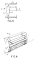
- a spacer 50 spaces a lens 52 from a plane 54, which may be a film or detector.
- the spacer 50 constitutes a lens mount or other structure that supports the lens relative to the plane 54.
- the lens 52 includes a refractive surface 56, a kinoform 60, and a bulk portion again formed by the refractive surface 56 and a base surface 58 in which kinoform 60 resides.
- the spacer 50 exhibits a temperature induced change in dimensions which varies the spacing 62 between lens 52 and plane 54.
- the structure of lens 52 is similar to that of lens 10. However, here the relationship between the bulk power ⁇ B and the kinoform power ⁇ K serves not only to correct temperature induced changes within the lens 52, but also, for temperature induced dimensional changes in the spacer 50.
- FIG. 6 An embodiment of the invention using a cylindrical lens appears in Figure 6.
- the material, values of ⁇ B , ⁇ K , and n are the same as the values for ⁇ B , ⁇ K , n 0 in Figures 1 and 2.
- Figure 6 depicts a cylindrical lens element 70.
- the cylindrical lens 70 focuses on a line and corrects for temperature induced focal length changes in the same manner as the examples of Figures 1 and 2.
- Lens 70 of Figure 6 has its kinoform grooves running parallel to axis 72. The focal length of these cylindrical lenses likewise can be made to remain substantially constant as temperature varies.
- spacer 50 spaces the lens 70 from the focal plane 54. That is, the lens 70 replaces the lens 52 in Figure 5.
- the same power conditions as in the lens of Figures 1 and 2 prevail.
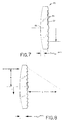
- Hybrid lens 80 corrects not only for temperature induced back focal length changes but for image quality by controlling the aberrations in the image by using an aspheric front surface 86 for the refractive surface, and kinoform grooves 82.
- this lens is a thermal to less than 1 part in 10 +4 .
- Details of the lens 80 in Figure 7 were obtained by first modeling lens 80 with an equivalent refractive lens having the following constructional data with the kinoform represented by a fictitious high index layer defined on one side by a sphere and on the other by an asphere.
- a kinoform is represented by a thin lens of central thickness zero and a very large index of refraction.
- An index of 10,001 was appropriate for this example.
- OPD optical path difference
- Zone # y (mm) Zone size (mm) Zone size (wavelengths) 1 0.063902 0.026472 32.481 2 0.090374 0.020316 24.927 3 0.110690 0.017128 21.016 4 0.127818 0.015092 18.318 5 0.142910 476 1.242816 0.001735 2.129 477 1.244551 0.001735 2.127 478 1.246284 0.001731 2.124 479 1.248015 0.001729 2.121 480 1.249744
- Hybrid lens 80 corrects not only for back focal length as temperature varies, but also for other aberrations.
- any desired general lens can then be described by a summation or superposition of such pairs of bulk power terms and kinoform athermalizing solutions, and such a general lens will be athermalized to any or all orders of spherical aberration.
- the kinoform side may be described mathematically in various ways, including a tabulation of the radius of each and every grooved facet.
- Sweatt model in which a kinoform is replaced with a vanishingly thin lens formed of a fictitious material of unrealisticly high refractive index, in such a way that the mathematically important optical properties of that material approach sufficiently close to the properties of a kinoform.
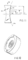
- a composite lens 130 as shown in Figure 10 has kinoforms 132 and 134 formed on both sides of the bulk refractive portion of the structure.
- Spherical aberration is corrected as described before by introducing a third power relationship for the second kinoform.
- the lenses of the invention fully incorporate passive means for reducing the temperature dependency of optical characteristics that vary with the geometry and refractive index of the lens.
- the lenses are nevertheless made of a single material.
- Figure 10 can also illustrate an example of an athermalized Germanium hybrid lens.
- lens 130 has the convex refractive surface 132.
- Kinoform 134 overlies a concave base surface 133. This lens is a thermal to one part in 10 8 at 10.6 microns.
- the lenses or systems do not fully athermalize the temperature dependence of the focal length or other characteristics but reduce them as required for particular applications. That is, the degree of athermalization is not complete, but the kinoform or kinoforms have powers which still compensate for the temperature induced changes in focal length or other characteristics of the lenses or devices.
- the kinoform accomplishes its athermalizing or temperature- dependence reduction end by exhibiting a power which is a substantial proportion of the bulk power.
- the kinoform-bulk ratio for athermalized lenses may vary from .15 to 10.0. Preferably the ratio is between .5 and 2.0.
- the kinoform power has a sign opposite to the bulk power in the a thermal case.
- the kinoform in the 1 athermalized hybrid lens contributes at least 4 times as much as the kinoform in the achromatized lens.
- the kinoform power contribution is at least 20% in absolute values, and in the achromatized lens the kinoform power contribution is less than 15%.
- the kinoform power is either larger than the bulk power or of opposite sign.
- the invention furnishes passively athermalized lenses and optical devices. It also provides lenses and devices whose variations in response to temperature changes are reduced passively to any desired degree.
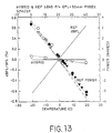
- Lens 200 fabricated of PMMA, comprises a front negative aspheric surface 202 and a rear aspheric base surface 204 on which is formed kinoform 206, itself a collection of grooves of varying size which are designated generally by 208.
- surfaces 202 and 204 and the intervening material provide the refractive power for lens 200.
- Lens 200 has an effective focal length of 50 mm at 0° C, an entrance pupil diameter of 12.5 mm and a relative aperture of f/4.
- Fig. 12 is a perspective photograph of it from the vantage point of looking up from the lower right quadrant (referenced to viewing the front surface face on) through the front surface with kinoform 206 appearing as imaged through front surface 202.
- Kinoform 206 has 1072 grooves which vary in radial width with the widest being close to the optical axis and the narrowest located at or near the largest clear diameter.
- Base surface 204 is spherical and has a curvature of 0.004306653067.
- Fig. 13 shows is the graphical equivalent of the data of the foregoing table showing that the focal length of the inventive lens remains substantially constant over the displayed temperature range.
- the departure in the variation of focal length from a completely flat curve is believed to be because of slight differences between actual and assumed values for the actual material variation of index with temperature.
Landscapes
- Physics & Mathematics (AREA)
- General Physics & Mathematics (AREA)
- Optics & Photonics (AREA)
- Lenses (AREA)
Description
where
Then:
Differentiating the value of B we get

| CURVATURE | THICKNESS | INDEX | MATERIAL |
| OBJ : 0.000000 | INFINITY | 1.495400 | |
| 1: -0.30724044 | 0.50000 | PLEXI | PLEXI |
| ASPHERIC: | |||
| K: 0.00000 | KC: 100 | ||
| IC: YES | CUF: 0.0000 | CCF: 100 | |
| A: 0.956778E-02 | B: 0.750010E-03 | C: 0.00E+0 | D: 0.00E+00 |
| AC: 0 BC:0 | CC: 100 | DC: 100 | |
| 2: 0.11126357 | 0.0 | 10001 | |
| STOP: 0.11122365 | 5.006346 | ||
| ASPHERIC: | |||
| K: 0.0 KC: 100 | |||
| IC: YES | CUF: 0.0 | CCF: 100 | |
| A: 0.417578E-06 | B: 0.0 | C: 0.0 | D: 0.0 |
| AC: 0 BC: 100 | CC: 100 | DC: 100 | |
| IMG: 0.00000 | 0.00000 | 100 | 100 |
| INFINITE CONJUGATES | T =0oC | T = 20°C | T = 40°C |
| EFL | 4.7579 | 4.7578 | 4.7592 |
| BFL | 5.0000 | 4.9993 | 5.0000 |
| FFL | -4.2097 | -4.2094 | -4.2103 |
| FNO | 1.9031 | 1.9031 | 1.9037 |
| IMG DIS | 5.0000 | 4.9991 | 5.0000 |
| CAL | 0.4994 | 0.5000 | 0.5007 |
| PARAXIAL IMAGE | |||
| HT | 0.0830 | 0.0830 | 0.0831 |
| ANG | 1.0000 | 1.0000 | 1.0000 |
| ENTRANCE PUPIL | |||
| DIA | 2.5000 | 2.5000 | 2.5000 |
| THI | 0.3178 | 0.3186 | 0.3196 |
| EXIT PUPIL | |||
| DIA | 2.6272 | 2.6269 | 2.6265 |
| THI | 0.0000 | 0.0000 | 0.0000 |
| STO DIA WAV | 2.6766 | 2.6762 | 2.6756 |
where:


a, b, c, d are aspheric departures.
Continuing:


| Zone # | y (mm) | Zone size (mm) | Zone size (wavelengths) |
| 1 | 0.063902 | 0.026472 | 32.481 |
| 2 | 0.090374 | 0.020316 | 24.927 |
| 3 | 0.110690 | 0.017128 | 21.016 |
| 4 | 0.127818 | 0.015092 | 18.318 |
| 5 | 0.142910 | ||
| 476 | 1.242816 | 0.001735 | 2.129 |
| 477 | 1.244551 | 0.001735 | 2.127 |
| 478 | 1.246284 | 0.001731 | 2.124 |
| 479 | 1.248015 | 0.001729 | 2.121 |
| 480 | 1.249744 |
Therefore,
| ACHROMAT | ATHERMAT | ||||
| Combination | Total Power | Bulk | Kino | Bulk | Kino |
| BK7/KINO | 1 | 0.9489 | 0.0511 | 1.3684 | -0.3684 |
| PMMA/KINO | 1 | 0.9433 | 0.0567 | -0.8769 | 1.8769 |
| GERM/KINO | 1 | 0.9974 | 0.0026 | 0.0843 | 0.9157 |
| KRS5/KINO | 1 | 0.9851 | 0.149 | -1.0240 | 2.0240 |
| KRS 5 is a Thalium-Bromide Thalium-Iodide material. GERM is Germanium BK7 is spectacle glass |
| ZONE | Y (mm) | SIZE (mm) | SIZE (waves) |
| 1 | 0.190.752 | 0.190752 | 301.44 |
| 2 | 0.269764 | 0.079012 | 124.86 |
| 3 | 0.330393 | 0.060628 | 95.81 |
| 4 | 0.381505 | 0.051112 | 80.77 |
| 5 | 0.426536 | 0.045031 | 71.16 |
| 6 | 0.467247 | 0.040711 | 64.34 |
| 7 | 0.504685 | 0.037438 | 59.16 |
| 8 | 0.539532 | 0.034847 | 55.07 |
| 9 | 0.572260 | 0.032729 | 51.72 |
| 10 | 0.603216 | 0.030956 | 48.92 |
| - | - | - | - |
| - | - | - | - |
| - | - | - | - |
| 1062 | 6.223288 | -- | -- |
| 1063 | 6.226224 | 0.002936 | 4.64 |
| 1064 | 6.229158 | 0.002935 | 4.64 |
| 1065 | 6.232091 | 0.002933 | 4.64 |
| 1066 | 6.235023 | 0.002932 | 4.63 |
| 1067 | 6.237954 | 0.002930 | 4.63 |
| 1068 | 6.240883 | 0.002929 | 4.63 |
| 1069 | 6.243811 | 0.002928 | 4.63 |
| 1070 | 6.246737 | 0.002926 | 4.62 |
| 1071 | 6.249662 | 0.002925 | 4.62 |
| 1072 | 6.252586 | 0.002924 | 4.62 |
| FIRST-ORDER PROPERTIES | |||
| REFERENCE | |||
| T = 0° | T = 20° | T = 40° | |
| EFL | 49.695 | 50.000 | 50.308 |
| BFL | 46.756 | 47.052 | 47.351 |
| t | 4.993 | 5.000 | 5.007 |
| RMS WFE | .002/.0036 | .002/.037 | .002/.037 |
| max defocus, waves | 3.590 | -0.111 | -3.810 |
| HYBRID | |||
| T = 0° | T = 20° | T = 40° | |
| EFL | 49.993 | 50.000 | 50.007 |
| BFL | 52.374 | 52.372 | 52.374 |
| t | 4.993 | 5.000 | 5.007 |
| RMS WFE | .001/.036 | .002/.034 | .002/.034 |
| max defocus, waves | .0.040 | -0.045 | -0.049 |
Claims (13)
- A lens (10) comprising a bulk portion having a first (14) and a second (16) surface, at least one of the surfaces (14, 16) of the bulk portion being curved, said bulk portion providing a refractive power, and at least one of the surfaces (16) of the bulk portion being provided with a kinoform (20), said kinoform providing kinoform power, the sum of said refractive power and said kinoform power being equal to the total optical power of said lens,
characterized in that the lens (10) is formed by a single material and in that the curved surface or surfaces of the bulk portion and the kinoform (20) are structured and arranged such that, with changes in temperature, the temperature induced changes in the refractive power and in the kinoform power have different signs, so that at least the total power and focal length (42) change with temperature in a predetermined way. - The lens as claimed in claim 1, wherein the ratio of said kinoform power to said refractive power is negative and substantially constant over the temperature change.
- The lens as claimed in claim 1, wherein said kinoform power is sufficient to athermalize the lens.
- The lens as claimed in claim 1, wherein said refractive surface is substantially spherical.
- The lens as claimed in claim 1, wherein said refractive surface is substantially cylindrical (70).
- The lens as claimed in claim 1, wherein one of the surfaces has an aspheric component (86).
- The lens as claimed in claims 1 to 6, wherein the grooves (82) of said kinoform (84) have aspheric profiles which change with temperature to compensate for changes in spherical aberration of said lens (80) with temperature.
- The lens as claimed in claims 1 to 7, wherein said at least one curved bulk surface (86) is aspheric and changes with temperature to compensate for changes in spherical aberration of said lens (80) with temperature.
- An optical device comprising a lens (52) having a bulk portion with a first (56) and a second (58) surface, at least one of the surfaces (56, 58) of the bulk portion being curved, said bulk portion providing a refractive power, and at least one of the surfaces (58) of the bulk portion being provided with a kinoform (60), said kinoform (60) providing kinoform power, the sum of said refractive power and said kinoform power being equal to the total optical power of said lens (52), the device further comprising a spacer (50) for spacing said lens from an optical target, said spacer exhibiting changes in dimensions in response to changes in temperature,
characterized in that the lens (52) is formed by a single material and in that the curved surface or surfaces (56, 58) of the bulk portion and the kinoform (60) are structured and arranged such that, with changes in temperature, the temperature induced changes in the refractive power and in the kinoform power have different signs, so that the device responds to the variations in temperature in both the spacer (50) and at least the total power and focal length in a predetermined way. - The optical device as claimed in claim 9, wherein said kinoform (60) has a power sufficient to compensate at least partially for the variations in the spacer (50) and in at least one of total power, focal length and spherical aberration in response to the changes in temperature.
- The optical device as claimed in claim 9, wherein said at least one curved bulk surface has aspheric components and said kinoform (60) has aspheric profiles, and the kinoform has sufficient aspheric kinoform power to offset changes in spherical aberration of said device at the optical target in response to changes in the temperature at at least one predetermined wavelength.
- A method of manufacturing an optical lens according to any one of claims 1 to 11,
comprising the steps of:
forming from a transparent material a lens (10, 30, 52, 70, 80, 200) comprising a bulk portion having a pair of refractive surfaces (14, 16, 56, 58, 202, 204) at least one of the surfaces being curved so that at least total power and focal length (42, L) of said lens bulk portion vary in response to changes in temperature; forming a kinoform (20, 33, 60, 206) integral with and made of the same material as said bulk portion on one of said surfaces (14, 16, 56, 58, 202, 204), said kinoform having a power sufficient to vary at least total power and focal length (42, L) of said lens in response to changes in temperature in a direction opposite to the direction which the changes in temperature impose on said bulk portion (10, 30, 52, 70, 80, 200) at at least one predetermined wavelength. - The method as claimed in claim 12,
characterized by the additional step of mounting said lens (52) in a mount (50), wherein the step of forming the kinoform (60) includes forming the kinoform (60) with enough power to also compensate for at least a portion of temperature-induced changes in the mount (50).
Applications Claiming Priority (3)
| Application Number | Priority Date | Filing Date | Title |
|---|---|---|---|
| US07/858,522 US5260828A (en) | 1992-03-27 | 1992-03-27 | Methods and means for reducing temperature-induced variations in lenses and lens devices |
| US858522 | 1992-03-27 | ||
| PCT/US1993/001324 WO1993020464A1 (en) | 1992-03-27 | 1993-02-12 | Methods and means for reducing temperature-induced variations in lenses and lens devices |
Publications (2)
| Publication Number | Publication Date |
|---|---|
| EP0632905A1 EP0632905A1 (en) | 1995-01-11 |
| EP0632905B1 true EP0632905B1 (en) | 1998-12-16 |
Family
ID=25328511
Family Applications (1)
| Application Number | Title | Priority Date | Filing Date |
|---|---|---|---|
| EP93905053A Revoked EP0632905B1 (en) | 1992-03-27 | 1993-02-12 | Methods and means for reducing temperature-induced variations in lenses and lens devices |
Country Status (7)
| Country | Link |
|---|---|
| US (1) | US5260828A (en) |
| EP (1) | EP0632905B1 (en) |
| JP (1) | JP3203251B2 (en) |
| KR (1) | KR0184609B1 (en) |
| CA (1) | CA2128328C (en) |
| DE (1) | DE69322627T2 (en) |
| WO (1) | WO1993020464A1 (en) |
Cited By (1)
| Publication number | Priority date | Publication date | Assignee | Title |
|---|---|---|---|---|
| US7012876B2 (en) | 1999-12-24 | 2006-03-14 | Koninklijke Philips Electronics N.V. | Optical scanning head |
Families Citing this family (66)
| Publication number | Priority date | Publication date | Assignee | Title |
|---|---|---|---|---|
| US20030043463A1 (en) * | 1992-03-30 | 2003-03-06 | Yajun Li | Athermalized plastic lens |
| US5629799A (en) * | 1992-07-16 | 1997-05-13 | Asahi Kogaku Kogyo Kabushiki Kaisha | Chromatic aberration correcting element and its application |
| JP3027065B2 (en) * | 1992-07-31 | 2000-03-27 | 日本電信電話株式会社 | Display / imaging device |
| US5473471A (en) * | 1993-04-16 | 1995-12-05 | Matsushita Electric Industrial Co., Ltd. | Complex lens with diffraction grating |
| US5581405A (en) * | 1993-12-29 | 1996-12-03 | Eastman Kodak Company | Hybrid refractive/diffractive achromatic camera lens and camera using such |
| US5543966A (en) * | 1993-12-29 | 1996-08-06 | Eastman Kodak Company | Hybrid refractive/diffractive achromatic camera lens |
| US5444250A (en) * | 1994-08-15 | 1995-08-22 | Hughes Aircraft Company | Optical warm stop with fresnel type reflective surface |
| US5737120A (en) * | 1995-03-14 | 1998-04-07 | Corning Incorporated | Low weight, achromatic, athermal, long wave infrared objective lens |
| US5693094A (en) * | 1995-05-09 | 1997-12-02 | Allergan | IOL for reducing secondary opacification |
| JPH0918897A (en) * | 1995-07-03 | 1997-01-17 | Canon Inc | 3D image display device |
| US5801889A (en) * | 1995-08-16 | 1998-09-01 | Eastman Kodak Company | Technique to eliminate scattered light in diffractive optical elements |
| EP0758753A3 (en) * | 1995-08-16 | 1997-08-06 | Eastman Kodak Co | Diffractive optical elements |
| US5745289A (en) * | 1996-06-21 | 1998-04-28 | Eastman Kodak Company | Athermalized diffractive optical elements |
| US5706139A (en) * | 1995-10-17 | 1998-01-06 | Kelly; Shawn L. | High fidelity optical system for electronic imaging |
| US5703721A (en) * | 1995-11-27 | 1997-12-30 | Eastman Kodak Company | Optical magnifier |
| JP3860261B2 (en) * | 1996-08-30 | 2006-12-20 | オリンパス株式会社 | Diffractive optical element having diffractive surfaces on both sides |
| JPH1090596A (en) * | 1996-09-13 | 1998-04-10 | Matsushita Electric Ind Co Ltd | Optical system with grating element and imaging device using the same |
| JPH10186230A (en) | 1996-10-29 | 1998-07-14 | Canon Inc | Lens system and optical equipment |
| US5808799A (en) * | 1996-10-31 | 1998-09-15 | Raytheon Ti Systems, Inc. | Infrared lens assembly with athermalization element and method |
| US6829091B2 (en) * | 1997-02-07 | 2004-12-07 | Canon Kabushiki Kaisha | Optical system and optical instrument with diffractive optical element |
| US6839174B1 (en) * | 1997-03-03 | 2005-01-04 | Olympus Corporation | Relief type diffraction optical element, optical system comprising the same and mold for manufacturing the same |
| JP3495884B2 (en) * | 1997-07-28 | 2004-02-09 | キヤノン株式会社 | Diffractive optical element and optical system using the same |
| US6134039A (en) * | 1998-01-27 | 2000-10-17 | Psc Scanning, Inc. | Wavelength dependent thermally compensated optical system |
| JP3559711B2 (en) * | 1998-06-12 | 2004-09-02 | キヤノン株式会社 | Scanning optical device and multi-beam scanning optical device |
| US6262844B1 (en) | 1998-08-28 | 2001-07-17 | Ksm Associates, Inc. | Optical systems employing stepped diffractive surfaces |
| JP2000090464A (en) * | 1998-09-07 | 2000-03-31 | Pioneer Electronic Corp | Optical pickup and information reproducing device |
| KR100444206B1 (en) * | 1998-09-17 | 2004-08-16 | 마쯔시다덴기산교 가부시키가이샤 | Coupling lens and semiconductor laser module |
| US6693745B1 (en) | 1999-09-14 | 2004-02-17 | Corning Incorporated | Athermal and high throughput gratings |
| EP1102250A3 (en) * | 1999-11-17 | 2003-03-26 | Konica Corporation | Optical pickup apparatus and objective lens |
| US6545807B2 (en) * | 1999-12-28 | 2003-04-08 | Pentax Corporation | Refractive-diffractive hybrid lens |
| US6865318B1 (en) | 2000-02-23 | 2005-03-08 | Schott Glass Technologies, Inc. | Athermal optical components |
| JP4587418B2 (en) * | 2000-09-27 | 2010-11-24 | キヤノン株式会社 | Diffractive optical element and optical system having the diffractive optical element |
| WO2002029797A1 (en) * | 2000-10-03 | 2002-04-11 | Koninklijke Philips Electronics N.V. | Optical scanning device |
| JP2002116314A (en) * | 2000-10-06 | 2002-04-19 | Sankyo Seiki Mfg Co Ltd | Diffracting element and optical pickup device |
| JP3634736B2 (en) * | 2000-10-12 | 2005-03-30 | ペンタックス株式会社 | Objective lens for optical head and optical system of optical head |
| US6545826B2 (en) | 2000-12-20 | 2003-04-08 | Finisar Corporation | Thermally compensated wavelength division demultiplexer and multiplexer and method of fabrication thereof |
| EP1276104B1 (en) * | 2001-07-11 | 2011-01-26 | Konica Minolta Opto, Inc. | Aberration compensating optical element, optical system, optical pickup device, recorder and reproducer |
| JP2003287675A (en) * | 2002-01-22 | 2003-10-10 | Konica Corp | Light convergence optical system, optical pickup device, recording and reproducing device, aberration correcting element, and objective |
| EP1520180B1 (en) * | 2002-07-05 | 2005-11-02 | Kamstrup A/S | Temperature compensated optical system based on a diffractive optical element |
| US6917471B2 (en) * | 2003-01-24 | 2005-07-12 | Sumitomo Electric Industries, Ltd. | Diffraction grating element |
| US7081978B2 (en) * | 2003-03-17 | 2006-07-25 | Raytheon Company | Beam combining device for multi-spectral laser diodes |
| KR20060030509A (en) * | 2003-07-09 | 2006-04-10 | 코닌클리케 필립스 일렉트로닉스 엔.브이. | Optics |
| JP2005070124A (en) * | 2003-08-27 | 2005-03-17 | Canon Inc | Optical scanning device and image forming apparatus using the same |
| KR20070015362A (en) * | 2003-10-15 | 2007-02-02 | 아리마 디바이시즈 코퍼레이션 | Read and write optics with temperature compensation |
| DE10351414A1 (en) * | 2003-10-30 | 2005-06-23 | Carl Zeiss Jena Gmbh | Laser scanning microscope with a non-descanned detection and / or observation beam path |
| ES2283162B1 (en) * | 2004-02-16 | 2008-09-16 | Universidad De Granada | OPTICAL SYSTEM FOR THE ACROMATIZATION OF THE HUMAN EYE. |
| JP4387855B2 (en) * | 2004-04-01 | 2009-12-24 | キヤノン株式会社 | Optical system |
| TW200617433A (en) * | 2004-11-19 | 2006-06-01 | Hon Hai Prec Ind Co Ltd | Diffractive optics lens and core insert for it and method of manufacturing the core insert |
| EP1856904A1 (en) * | 2005-03-07 | 2007-11-21 | Thomson Licensing SAS | Film printing head having hybrid lenses |
| US7262914B2 (en) * | 2005-07-22 | 2007-08-28 | Stuart Gary Mirell | Method and apparatus for generating and detecting duality modulated electromagnetic radiation |
| FR2902896B1 (en) * | 2006-06-21 | 2008-12-12 | Essilor Int | OPTICAL CONDUIT FOR REALIZING AN ELECTRONIC DISPLAY ARRANGEMENT |
| JP5128808B2 (en) * | 2006-12-06 | 2013-01-23 | スリーエム イノベイティブ プロパティズ カンパニー | Fresnel lens |
| KR100924349B1 (en) * | 2008-03-05 | 2009-10-30 | 주식회사 하이닉스반도체 | How to correct aberration by lens heating |
| EP2278630A1 (en) * | 2008-04-08 | 2011-01-26 | Sharp Kabushiki Kaisha | Optical member for light concentration and concentrator photovoltaic module |
| US8134691B2 (en) * | 2010-03-18 | 2012-03-13 | Mitutoyo Corporation | Lens configuration for a thermally compensated chromatic confocal point sensor |
| DE102010034020A1 (en) * | 2010-08-11 | 2012-02-16 | Fraunhofer-Gesellschaft zur Förderung der angewandten Forschung e.V. | Surface structure and Fresnel lens and tool for producing a surface structure |
| WO2014197066A2 (en) * | 2013-03-14 | 2014-12-11 | Drs Rsta, Inc. | Single element radiometric lens |
| US9638838B1 (en) * | 2015-12-09 | 2017-05-02 | Newmax Technology Co., Ltd. | Lens having microstructures |
| EP4235230A1 (en) | 2016-09-13 | 2023-08-30 | Facebook Technologies, LLC | Fresnel lens with dynamic draft for reduced optical artifacts |
| US10502956B2 (en) | 2017-06-27 | 2019-12-10 | Microsoft Technology Licensing, Llc | Systems and methods of reducing temperature gradients in optical waveguides |
| US11269119B2 (en) * | 2018-11-16 | 2022-03-08 | United States Of America, As Represented By The Secretary Of The Army | Monolithic double diffractive kinoform doublet |
| TWI745905B (en) * | 2020-03-27 | 2021-11-11 | 黃旭華 | Self-temperature focus compensation device |
| CN111722526B (en) * | 2020-06-24 | 2023-04-18 | 昆明物理研究所 | Multi-view-field switching calibration control method based on temperature compensation and computer readable storage medium |
| WO2022170287A2 (en) | 2021-06-07 | 2022-08-11 | Panamorph, Inc. | Near-eye display system |
| US12204096B2 (en) | 2021-06-07 | 2025-01-21 | Panamorph, Inc. | Near-eye display system |
| CN113791466B (en) * | 2021-11-10 | 2022-03-01 | 中国空气动力研究与发展中心低速空气动力研究所 | Wavy Fresnel lens and preparation method thereof |
Family Cites Families (15)
| Publication number | Priority date | Publication date | Assignee | Title |
|---|---|---|---|---|
| US4210391A (en) * | 1977-09-14 | 1980-07-01 | Cohen Allen L | Multifocal zone plate |
| DE3377535D1 (en) * | 1982-10-27 | 1988-09-01 | Pilkington Plc | Bifocal contact lens comprising a plurality of concentric zones |
| JPS61224152A (en) * | 1985-03-29 | 1986-10-04 | Toshiba Corp | Optical device |
| US5121979A (en) * | 1986-05-14 | 1992-06-16 | Cohen Allen L | Diffractive multifocal optical device |
| US5017000A (en) * | 1986-05-14 | 1991-05-21 | Cohen Allen L | Multifocals using phase shifting |
| GB8807385D0 (en) * | 1988-03-29 | 1988-05-05 | British Telecomm | Semiconductor device assembly |
| US5116111A (en) * | 1988-04-01 | 1992-05-26 | Minnesota Mining And Manufacturing Company | Multi-focal diffractive ophthalmic lenses |
| US5161057A (en) * | 1988-09-12 | 1992-11-03 | Johnson Kenneth C | Dispersion-compensated fresnel lens |
| GB8829819D0 (en) * | 1988-12-21 | 1989-02-15 | Freeman Michael H | Lenses and mirrors |
| NL9000135A (en) * | 1989-01-30 | 1990-08-16 | Seiko Epson Corp | FOCUSING MECHANISM AND OPTICAL HEAD. |
| US5044706A (en) * | 1990-02-06 | 1991-09-03 | Hughes Aircraft Company | Optical element employing aspherical and binary grating optical surfaces |
| JPH0416910A (en) * | 1990-05-11 | 1992-01-21 | Omron Corp | Optical lens |
| US5138495A (en) * | 1990-07-27 | 1992-08-11 | Matsushita Electric Industrial Co., Ltd. | Diffractive optical lens |
| US5148317A (en) * | 1991-06-24 | 1992-09-15 | The United States Of America As Represented By The Secretary Of The Air Force | Diffractive optical element for collimating and redistributing Gaussian input beam |
| US5151823A (en) * | 1991-09-23 | 1992-09-29 | Hughes Aircraft Company | Biocular eyepiece optical system employing refractive and diffractive optical elements |
-
1992
- 1992-03-27 US US07/858,522 patent/US5260828A/en not_active Expired - Lifetime
-
1993
- 1993-02-12 CA CA002128328A patent/CA2128328C/en not_active Expired - Fee Related
- 1993-02-12 WO PCT/US1993/001324 patent/WO1993020464A1/en not_active Ceased
- 1993-02-12 EP EP93905053A patent/EP0632905B1/en not_active Revoked
- 1993-02-12 DE DE69322627T patent/DE69322627T2/en not_active Revoked
- 1993-02-12 JP JP51742993A patent/JP3203251B2/en not_active Expired - Fee Related
-
1994
- 1994-09-27 KR KR1019940703358A patent/KR0184609B1/en not_active Expired - Fee Related
Cited By (1)
| Publication number | Priority date | Publication date | Assignee | Title |
|---|---|---|---|---|
| US7012876B2 (en) | 1999-12-24 | 2006-03-14 | Koninklijke Philips Electronics N.V. | Optical scanning head |
Also Published As
| Publication number | Publication date |
|---|---|
| CA2128328A1 (en) | 1993-10-14 |
| JP3203251B2 (en) | 2001-08-27 |
| JPH07505235A (en) | 1995-06-08 |
| DE69322627D1 (en) | 1999-01-28 |
| KR950701080A (en) | 1995-02-20 |
| DE69322627T2 (en) | 1999-05-06 |
| KR0184609B1 (en) | 1999-05-15 |
| CA2128328C (en) | 1999-08-31 |
| WO1993020464A1 (en) | 1993-10-14 |
| EP0632905A1 (en) | 1995-01-11 |
| US5260828A (en) | 1993-11-09 |
Similar Documents
| Publication | Publication Date | Title |
|---|---|---|
| EP0632905B1 (en) | Methods and means for reducing temperature-induced variations in lenses and lens devices | |
| US10175493B1 (en) | Projection lens system, projection apparatus, sensing module and electronic device | |
| US5818632A (en) | Multi-element lens system | |
| WO2000013048A1 (en) | Optical systems employing stepped diffractive surfaces | |
| Greisukh et al. | Diffractive–refractive correction units<? A3B2 show [pmg: line-break justify=" yes"/]?> for plastic compact zoom lenses | |
| EP0840144A1 (en) | Lens system having diffracting surface and refracting surface and optical apparatus using the lens system | |
| US5078513A (en) | Achromatic waveguide lenses | |
| Corsetti et al. | Color correction in the infrared using gradient-index materials | |
| Londono et al. | Athermalization of a single-component lens with diffractive optics | |
| Wang et al. | Optical design of athermalized infrared dual-band annular folded lens with multilayer imaging diffractive optical elements | |
| Hassan et al. | Compact athermalized LWIR objective lens | |
| RU2642173C1 (en) | Athermalised wideangle lens for ir spectral region | |
| Riedl et al. | Analysis and performance limits of diamond-turned diffractive lenses for the 3-5 and 8-12 micrometer regions | |
| Bigwood | New infrared optical systems using diffractive optics | |
| GB2068585A (en) | Single Element Optical System | |
| Ries et al. | Silicone-on-glass (SOG) diffractive optical elements (DOE) for the correction of chromatic aberrations and lens shape | |
| Kucukcelebi | Optical design of an athermalised dual field of view step zoom optical system in MWIR | |
| Kucukcelebi et al. | Passive athermalization of MWIR optical designs utilizing different infrared optical materials | |
| Fein et al. | SWaP advantage of replacing high performance glass achromatic doublet with a polymeric nanolayer GRIN achromatic singlet | |
| Behrmann et al. | Hybrid (refractive/diffractive) optics | |
| CN117031700A (en) | Folded-super mixed athermalized infrared optical system | |
| Greisukh et al. | Afocal corrector for expanding the operating spectral and temperature ranges of an infrared system: design methodology and achieved optical performance | |
| Morris et al. | Achrotech: achromat cost versus performance for conventional, diffractive, and GRIN components | |
| Huang et al. | Wavefront measurement of plastic lenses for mobile-phone applications | |
| Larrategui et al. | Sensitivity analysis of the CTE and thermo-optical coefficients of a passively athermalized lens |
Legal Events
| Date | Code | Title | Description |
|---|---|---|---|
| PUAI | Public reference made under article 153(3) epc to a published international application that has entered the european phase |
Free format text: ORIGINAL CODE: 0009012 |
|
| 17P | Request for examination filed |
Effective date: 19940830 |
|
| AK | Designated contracting states |
Kind code of ref document: A1 Designated state(s): CH DE FR GB LI NL SE |
|
| 17Q | First examination report despatched |
Effective date: 19970213 |
|
| GRAG | Despatch of communication of intention to grant |
Free format text: ORIGINAL CODE: EPIDOS AGRA |
|
| GRAG | Despatch of communication of intention to grant |
Free format text: ORIGINAL CODE: EPIDOS AGRA |
|
| GRAH | Despatch of communication of intention to grant a patent |
Free format text: ORIGINAL CODE: EPIDOS IGRA |
|
| GRAH | Despatch of communication of intention to grant a patent |
Free format text: ORIGINAL CODE: EPIDOS IGRA |
|
| GRAA | (expected) grant |
Free format text: ORIGINAL CODE: 0009210 |
|
| AK | Designated contracting states |
Kind code of ref document: B1 Designated state(s): CH DE FR GB LI NL SE |
|
| ET | Fr: translation filed | ||
| REG | Reference to a national code |
Ref country code: CH Ref legal event code: NV Representative=s name: R. A. EGLI & CO. PATENTANWAELTE Ref country code: CH Ref legal event code: EP |
|
| REF | Corresponds to: |
Ref document number: 69322627 Country of ref document: DE Date of ref document: 19990128 |
|
| PLBQ | Unpublished change to opponent data |
Free format text: ORIGINAL CODE: EPIDOS OPPO |
|
| PLBI | Opposition filed |
Free format text: ORIGINAL CODE: 0009260 |
|
| PLBF | Reply of patent proprietor to notice(s) of opposition |
Free format text: ORIGINAL CODE: EPIDOS OBSO |
|
| 26 | Opposition filed |
Opponent name: CANON INC. CORPORATE INTELLECTUAL PROPERTY AND LEG Effective date: 19990916 |
|
| NLR1 | Nl: opposition has been filed with the epo |
Opponent name: CANON INC. CORPORATE INTELLECTUAL PROPERTY AND LEG |
|
| PLBF | Reply of patent proprietor to notice(s) of opposition |
Free format text: ORIGINAL CODE: EPIDOS OBSO |
|
| PGFP | Annual fee paid to national office [announced via postgrant information from national office to epo] |
Ref country code: FR Payment date: 20010111 Year of fee payment: 9 |
|
| PGFP | Annual fee paid to national office [announced via postgrant information from national office to epo] |
Ref country code: SE Payment date: 20010117 Year of fee payment: 9 |
|
| PGFP | Annual fee paid to national office [announced via postgrant information from national office to epo] |
Ref country code: GB Payment date: 20010118 Year of fee payment: 9 |
|
| PGFP | Annual fee paid to national office [announced via postgrant information from national office to epo] |
Ref country code: DE Payment date: 20010119 Year of fee payment: 9 |
|
| PGFP | Annual fee paid to national office [announced via postgrant information from national office to epo] |
Ref country code: CH Payment date: 20010122 Year of fee payment: 9 |
|
| PGFP | Annual fee paid to national office [announced via postgrant information from national office to epo] |
Ref country code: NL Payment date: 20010129 Year of fee payment: 9 |
|
| RDAH | Patent revoked |
Free format text: ORIGINAL CODE: EPIDOS REVO |
|
| RDAG | Patent revoked |
Free format text: ORIGINAL CODE: 0009271 |
|
| STAA | Information on the status of an ep patent application or granted ep patent |
Free format text: STATUS: PATENT REVOKED |
|
| 27W | Patent revoked |
Effective date: 20010223 |
|
| GBPR | Gb: patent revoked under art. 102 of the ep convention designating the uk as contracting state |
Free format text: 20010223 |
|
| REG | Reference to a national code |
Ref country code: CH Ref legal event code: PL |
|
| NLR2 | Nl: decision of opposition |