EP0632261A2 - Système de détection d'une puissance basse dans au moins un cylindre d'un moteur à plusieurs cylindres - Google Patents
Système de détection d'une puissance basse dans au moins un cylindre d'un moteur à plusieurs cylindres Download PDFInfo
- Publication number
- EP0632261A2 EP0632261A2 EP94106657A EP94106657A EP0632261A2 EP 0632261 A2 EP0632261 A2 EP 0632261A2 EP 94106657 A EP94106657 A EP 94106657A EP 94106657 A EP94106657 A EP 94106657A EP 0632261 A2 EP0632261 A2 EP 0632261A2
- Authority
- EP
- European Patent Office
- Prior art keywords
- cylinder
- engine
- cylinders
- low power
- resonant frequency
- Prior art date
- Legal status (The legal status is an assumption and is not a legal conclusion. Google has not performed a legal analysis and makes no representation as to the accuracy of the status listed.)
- Granted
Links
Images


Classifications
-
- G—PHYSICS
- G01—MEASURING; TESTING
- G01M—TESTING STATIC OR DYNAMIC BALANCE OF MACHINES OR STRUCTURES; TESTING OF STRUCTURES OR APPARATUS, NOT OTHERWISE PROVIDED FOR
- G01M15/00—Testing of engines
- G01M15/04—Testing internal-combustion engines
- G01M15/12—Testing internal-combustion engines by monitoring vibrations
-
- F—MECHANICAL ENGINEERING; LIGHTING; HEATING; WEAPONS; BLASTING
- F02—COMBUSTION ENGINES; HOT-GAS OR COMBUSTION-PRODUCT ENGINE PLANTS
- F02D—CONTROLLING COMBUSTION ENGINES
- F02D35/00—Controlling engines, dependent on conditions exterior or interior to engines, not otherwise provided for
- F02D35/02—Controlling engines, dependent on conditions exterior or interior to engines, not otherwise provided for on interior conditions
-
- F—MECHANICAL ENGINEERING; LIGHTING; HEATING; WEAPONS; BLASTING
- F02—COMBUSTION ENGINES; HOT-GAS OR COMBUSTION-PRODUCT ENGINE PLANTS
- F02D—CONTROLLING COMBUSTION ENGINES
- F02D41/00—Electrical control of supply of combustible mixture or its constituents
- F02D41/24—Electrical control of supply of combustible mixture or its constituents characterised by the use of digital means
- F02D41/26—Electrical control of supply of combustible mixture or its constituents characterised by the use of digital means using computer, e.g. microprocessor
- F02D41/28—Interface circuits
- F02D2041/286—Interface circuits comprising means for signal processing
- F02D2041/288—Interface circuits comprising means for signal processing for performing a transformation into the frequency domain, e.g. Fourier transformation
-
- F—MECHANICAL ENGINEERING; LIGHTING; HEATING; WEAPONS; BLASTING
- F02—COMBUSTION ENGINES; HOT-GAS OR COMBUSTION-PRODUCT ENGINE PLANTS
- F02D—CONTROLLING COMBUSTION ENGINES
- F02D2200/00—Input parameters for engine control
- F02D2200/02—Input parameters for engine control the parameters being related to the engine
- F02D2200/025—Engine noise, e.g. determined by using an acoustic sensor
-
- F—MECHANICAL ENGINEERING; LIGHTING; HEATING; WEAPONS; BLASTING
- F02—COMBUSTION ENGINES; HOT-GAS OR COMBUSTION-PRODUCT ENGINE PLANTS
- F02D—CONTROLLING COMBUSTION ENGINES
- F02D2200/00—Input parameters for engine control
- F02D2200/02—Input parameters for engine control the parameters being related to the engine
- F02D2200/10—Parameters related to the engine output, e.g. engine torque or engine speed
- F02D2200/1015—Engines misfires
-
- F—MECHANICAL ENGINEERING; LIGHTING; HEATING; WEAPONS; BLASTING
- F02—COMBUSTION ENGINES; HOT-GAS OR COMBUSTION-PRODUCT ENGINE PLANTS
- F02D—CONTROLLING COMBUSTION ENGINES
- F02D35/00—Controlling engines, dependent on conditions exterior or interior to engines, not otherwise provided for
- F02D35/02—Controlling engines, dependent on conditions exterior or interior to engines, not otherwise provided for on interior conditions
- F02D35/027—Controlling engines, dependent on conditions exterior or interior to engines, not otherwise provided for on interior conditions using knock sensors
Definitions
- cylinder pressure resonance phenomenon is well known and understood. Furthermore, as reflected by U.S. Patent Nos. 4,895,121 (McCoy et al.), 5,119,783 ( Komurasaki) and 5,144,929 (Hosoya et al.), this phenomenon is used in methods and apparatus for controlling engine operation for suppressing the occurrence of autoignition, i.e., knocking.
- vibration sensors are used to monitor engine cylinder resonant frequencies produced during operation of a multicylinder engine, and the magnitude of the resonance frequency peaks are evaluated as a knocking indicator. The frequency range in which the resonant frequency occurs is not taken into consideration and the only abnormal combustion condition detected is knocking.
- Tests for the identification of low power cylinders in multi-cylinder engines which are not dependent on the detection of knocking are known. However, these tests can only be performed during engine idling condition through the use of cylinder cut-out techniques. Thus, such tests are not suitable for an on-board vehicle diagnostic system, and cannot be used to perform diagnostic tests under on-the-road driving conditions.
- a primary object of the invention is to provide a diagnostic system for internal combustion engines by which the performance of individual cylinders of a multi-cylinder engine can be monitored and low power conditions, including misfiring, identified.
- Another object of this invention is to provide a method and apparatus for detecting engine performance deficiencies that are not limited to the occurrence of knocking.
- a further object of the present invention is to achieve the foregoing objects by adaptation of existing monitoring technology.
- a vibration sensor to monitor the resonant frequency of each cylinder of a multi-cylinder engine and using the detection of an abnormal resonant frequency, i.e., one outside of an established range, as an indication that one or more specific cylinders is operating at an improper power level.
- Vibration signals associated with combustion in each cylinder can be used to perform FFT (Fast Fourier Transformation) with the resonant frequencies (combustion resonant frequencies) for all engine cycles being determined and an averaged resonant frequency for each cylinder obtained. Shifts in the averaged resonant frequency or the detection of no resonance for only one of the cylinders can be used as an indication that the cylinder with the shifted resonant frequency or no resonance is experiencing a low power condition, including misfiring.
- FFT Fast Fourier Transformation
- self-diagnostics can be conducted to determine failed sensors by using redundant information provided by each vibration sensor.
- a pair of sensors may measure the same engine event (e.g., valve closing for a particular cylinder) and the portion of their vibration signals corresponding to the event compared.
- the present invention utilizes the discovery of a relationship between resonant frequency (i.e., the dominant frequency in the frequency spectrum of the vibrations associated with the combustion process of an engine) and combustion performance to determine when a low power condition exists in an engine cylinder.
- Cylinder pressure resonance is a well known and understood phenomenon, i.e., that the resonant frequency of the vibrations produced by the combustion process in the combustion chambers of an internal combustion engine varies directly with the speed of sound and inversely with respect to the bore size (diameter) of the combustion chamber.
- Analysis of the variables affecting the speed of sound yields combustion chamber temperature as the primary factor affecting the speed of sound, and thus, the resonant frequency, and cylinder temperature varies during engine operation, due to such factors as engine speed and load.
- resonant frequency will vary, it will normally lie in a range of about 2.5 KHz to 7.5 KHz dependent on the cylinder bore (e.g., for a cylinder bore of 6.25", a resonant frequency of about 2.5-4.0 KHz can be expected).
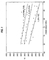
- Fig. 1 shows experimental results depicting the resonant frequency spectrum of signals from a vibration sensor as a function of crank angle under different levels of power as simulated by reducing the fuel rate to the injector to 75%, 50% and 25% of the normal fueling rate. As can be seen, the resonant frequency decreases as the combustion process proceeds to the end.
- a resonant frequency shift can be observed as a function of the level of power, i.e., as the fuel rate decreases (and with it the power level), the resonant frequency of the cylinder shifts to a lower frequency.
- piezoelectric vibration sensors For purposes of measuring the resonant frequency of each cylinder of a multi-cylinder engine conventional "knock" sensors, such as piezoelectric vibration sensors, can be used. Such sensors, while subject to a lack of consistency in sensitivity, are acceptable for the present purposes due to the fact that it is the frequency at which the resonant frequency peak occurs that is important to the present invention and the magnitude of the resonant frequency peak need only be determined to have exceeded a minimum threshold level to be recognized as such. In addition, piezoelectric vibration sensors are low in cost, reliable and durable in comparison to other accelerometer-type vibration sensors.
- Knock sensors are primary of two types: resonant and nonresonant types. Even though both of these types are suitable for knock detection, for the purposes of the present invention, nonresonant types are preferred (despite the fact that they produce a lower output). In particular, nonresonant types of knock sensors are suitable because they provide a roughly constant sensitivity in a certain frequency range and can be used regardless of engine model. On the other hand, resonant types must be adjusted for each different engine model, and more importantly, it is difficult to obtain consistently accurate resonance measurements with this type of sensor due to difficulties associated with trying to distinguish the resonance of the sensor from that associated with the combustion process.
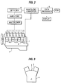
- Fig. 2 shows an engine 1 with the low power detection apparatus in accordance with a preferred embodiment of the present invention in which vibration sensors 3 are mounted on a valve housing cover 5 in proximity to each engine cylinder.
- the sensors 3 can be mounted to the cylinder block between two adjacent head assemblies at each pair of cylinders, as diagrammatically represented in Fig. 3.
- Fig. 3 it should be recognized that what will be suitable sensor mounting locations will vary from engine to engine and the primary factor governing selection is that they be sensitive to combustion forces and at least relatively insensitive to other engine forces, with other factors, such as accessibility, being considered as well.
- time domain windowing based on crank angle can be used to effectively separate engine events that do not overlap the combustion event, such as intake and exhaust valve closings.
- a crank shaft angle indicator 7 such as a crank shaft timing encoder or a magnetic pickup which produces a pulse once each rotation of the crank shaft 8
- data processor 9 to confine the signals from the sensors 3 which are to be processed by data processor 9 to only those obtained during a specific crank angle interval, e.g., from top dead center (TDC) to 30° after top dead center (ATDC) during each power stroke.
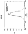
- a window known as a Hamming window, that tapers smoothly to zero at each end (analogous to a bell-shaped curve) is used to eliminate abrupt discontinuities at the beginning and end of a windowed series.
- a bandpass filter 11 can be used to further separate the combustion-related vibration from that associated with other engine events. For example, for an engine having a 6.25" bore, a bandpass filter 11 can be used which will only pass vibrations in the range from 2.0 KHz to 4.5 KHz.
- the FFT with parabolic fitting developed involved the steps of:
- resonant combustion cycles are distinguished from nonresonant combustion cycles, the resonant frequency of each cylinder is estimated for each resonant combustion cycle, a statistical analysis of the estimated resonant frequency is performed for each engine cylinder, and the mean of these frequencies determined and used for the final estimated resonant frequency for the respective engine cylinder.
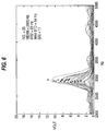
- Fig. 6 the frequency spectrum of signals from a sensor for each of 48 cycles, of an engine operating under steady-state conditions, can be seen with the resonant frequency estimated and denoted by a "o".
- a resonant frequency distribution over all of the cylinders can be obtained, and from which individual low power cylinders can be identified by the fact that low power cylinders will have a significantly lower resonant frequencies and misfiring cylinders will have no resonance detected.
- Fig. 7 shows the resonant frequency distribution for four engine cylinders where cylinder 1 is operated at normal and three reduced power levels while the other three monitored cylinders were operated at normal power levels. As can be seen, cylinder 1 evidences a substantially reduced resonant frequency when operated at a 50% power level and no resonant frequency when operated at a 25% of the normal power level.
- the engine speed can be determined from a once-per-revolution pulse signal issued by a magnetic pickup sensor 7 each time TDC for a cylinder occurs.
- Engine load optionally, can be based on an engine load signal from the engine's electronic control module (ECM) or a throttle position sensor if the engine is not equipped with an ECM.
- ECM electronice control module
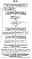
- the diagnostic scheme is not performed since combustion is likely to be occurring too smoothly for a reasonable degree of accuracy to be obtainable; preferably, the engine should be operating at relatively low speed with a light to medium load to assure the highest degree of accuracy.
- the diagnostic scheme of Fig. 8b is commenced.
- the data processor examines a snapshot of data from the vibration sensors 3 taken at a sampling rate fs of, e.g., about 10,000 Hz for a sufficient number of consecutive engine cycles, NUM_CYC , e.g., 40-50 cycles. This data is windowed over, e.g., from TDC to 30° ATDC of each power stroke and bandpassed, e.g., at about 2,000-4,500 Hz, after which FFT is performed on the data. If resonance is detected, the resonant cycle count r is incremented by 1 and parabolic fitting is performed, as described above.
- the power level of each cylinder is then classified and saved in a STATUS vector which is composed of the classified power level flag (a NO_RES status being assigned when no resonance is detected in a cylinder), having a count number corresponding to how many times this diagnostic scheme has been performed as, for example, rows and the number of the particular cylinder to which the power level classification pertains as, for example, columns.
- the count number is incremented by 1 and once the count reaches a preset number that is large enough to provide sufficient accuracy, the number of occurrences of low power level indications is determined for each cylinder from the STATUS vectors and LOWPOWER warnings are output to a visual display for those cylinders having the highest number of low power occurrences or any cylinder having more than a prescribed number or percentage of low power STATUS vectors.
- Fig. 8a before a warning indication is displayed, to prevent false alarms due to sensor failures, self-diagnostics are performed on the sensors, with a replace sensor indication being issued, instead, if a failed sensor is detected.
- Sensor failure diagnostics can be performed by using redundant information provided by each sensor 3. For example, two sensors may measure the same event in their vibration signals, such as intake/exhaust valve closings, and by examining the portion of the signals corresponding to the jointly-monitored event, failed sensors and even sensor-to-sensor variations can be determined.
- the present invention will find a wide range of application to single cylinder power loss diagnostics for multi-cylinder internal combustion engines, being applicable to both Diesel and spark ignition engines.
- the inventive diagnostic system will find particular utility as an on-board, vehicle diagnostics for engines ranging from 4 cylinder to 16 cylinder engines.
- the invention will significantly reduce the time required to locate low power cylinders in service as well as costly total down-time.
Applications Claiming Priority (2)
| Application Number | Priority Date | Filing Date | Title |
|---|---|---|---|
| US84071 | 1993-06-30 | ||
| US08/084,071 US5392642A (en) | 1993-06-30 | 1993-06-30 | System for detection of low power in at least one cylinder of a multi-cylinder engine |
Publications (3)
| Publication Number | Publication Date |
|---|---|
| EP0632261A2 true EP0632261A2 (fr) | 1995-01-04 |
| EP0632261A3 EP0632261A3 (fr) | 1995-04-05 |
| EP0632261B1 EP0632261B1 (fr) | 1997-08-06 |
Family
ID=22182709
Family Applications (1)
| Application Number | Title | Priority Date | Filing Date |
|---|---|---|---|
| EP94106657A Expired - Lifetime EP0632261B1 (fr) | 1993-06-30 | 1994-04-28 | Système de détection d'une puissance basse dans au moins un cylindre d'un moteur à plusieurs cylindres |
Country Status (4)
| Country | Link |
|---|---|
| US (1) | US5392642A (fr) |
| EP (1) | EP0632261B1 (fr) |
| JP (1) | JP2517213B2 (fr) |
| DE (1) | DE69404773T2 (fr) |
Cited By (7)
| Publication number | Priority date | Publication date | Assignee | Title |
|---|---|---|---|---|
| GB2296325A (en) * | 1994-12-20 | 1996-06-26 | Snap On Tools Corp | Accelerometer-based apparatus for determining engine power balance |
| DE19622848A1 (de) * | 1995-06-07 | 1996-12-12 | Cummins Engine Co Inc | System und Verfahren zur Detektion von Fehlzündungen in einem Motor |
| WO2001071363A1 (fr) * | 2000-03-20 | 2001-09-27 | Abb Research Ltd | Procede de determination de la vitesse de rotation d'un moteur a cage d'ecureuil et logiciel d'ordinateur de mise en oeuvre du procede |
| WO2001071362A1 (fr) * | 2000-03-20 | 2001-09-27 | Abb Research Ltd | Procede de determination de la vitesse de rotation d'un moteur et logiciel informatique de mise en oeuvre du procede |
| WO2003001175A1 (fr) * | 2001-06-26 | 2003-01-03 | Engines Pdm Ltd. | Procede et systeme de diagnostic universel pour moteurs |
| WO2006118296A1 (fr) | 2005-04-27 | 2006-11-09 | Toyota Jidosha Kabushiki Kaisha | Dispositif de determination du cognement pour moteur a combustion interne |
| EP1752754A2 (fr) | 2005-08-10 | 2007-02-14 | General Electric Company | Procédé et appareil pour l'analyse de la signature d'un signal pour la détection d'un événement dans une machine rotative |
Families Citing this family (36)
| Publication number | Priority date | Publication date | Assignee | Title |
|---|---|---|---|---|
| US6243641B1 (en) * | 1995-06-07 | 2001-06-05 | Cummins Engine Company, Inc. | System and method for detecting engine cylinder misfire |
| DE19805299A1 (de) * | 1998-02-10 | 1999-08-12 | Deutz Ag | Elektronische Regeleinrichtung |
| DE19844085C1 (de) * | 1998-09-25 | 2000-03-16 | Siemens Ag | Verfahren zum Steuern einer Brennkraftmaschine abhängig von einem Abgasdruck |
| US6185995B1 (en) * | 1999-07-06 | 2001-02-13 | Abb Flexible Automation Inc. | Method and system for determining proper assembly of engine components |
| US6388444B1 (en) * | 2000-01-13 | 2002-05-14 | Ford Global Technologies, Inc. | Adaptive method for detecting misfire in an internal combustion engines using an engine-mounted accelerometer |
| US6273064B1 (en) | 2000-01-13 | 2001-08-14 | Ford Global Technologies, Inc. | Controller and control method for an internal combustion engine using an engine-mounted accelerometer |
| US6349685B1 (en) * | 2000-05-09 | 2002-02-26 | Ford Global Technologies, Inc. | Method and system for operating valves of a camless internal combustion engine |
| JP2001330593A (ja) * | 2000-05-19 | 2001-11-30 | Ryoei Engineering Kk | 鋳造成形品の連通孔検査方法およびその装置 |
| DE10048060B4 (de) * | 2000-09-28 | 2006-07-06 | Robert Bosch Gmbh | Verfahren zur Klopferkennung |
| US7444231B2 (en) * | 2004-11-18 | 2008-10-28 | Westport Power Inc. | Method of mounting an accelerometer on an internal combustion engine and increasing signal-to-noise ratio |
| US7174879B1 (en) | 2006-02-10 | 2007-02-13 | Ford Global Technologies, Llc | Vibration-based NVH control during idle operation of an automobile powertrain |
| DE102006056860A1 (de) * | 2006-12-01 | 2008-06-05 | Conti Temic Microelectronic Gmbh | Verfahren und Vorrichtung zur Steuerung der Betriebsweise einer Brennkraftmaschine |
| JP4640324B2 (ja) * | 2006-12-01 | 2011-03-02 | 株式会社デンソー | 多気筒内燃機関の制御装置 |
| US8051702B2 (en) * | 2008-11-12 | 2011-11-08 | Altronic, Inc. | Vibration monitor |
| EP2547991A4 (fr) * | 2010-03-19 | 2017-10-04 | ABB Oy | Procédé et système de surveillance de la santé pour entraînements |
| JP5395201B2 (ja) * | 2012-03-14 | 2014-01-22 | 三菱電機株式会社 | 内燃機関のノック制御装置 |
| US9316565B2 (en) | 2013-01-14 | 2016-04-19 | Cummins Inc. | Exhaust manifold pressure based misfire detection for internal combustion engines |
| KR20170016459A (ko) * | 2014-06-17 | 2017-02-13 | 스카니아 씨브이 악티에볼라그 | 내연 기관 및 내연 기관의 작동 조건을 검출하는 방법 |
| US9556810B2 (en) | 2014-12-31 | 2017-01-31 | General Electric Company | System and method for regulating exhaust gas recirculation in an engine |
| US9752949B2 (en) | 2014-12-31 | 2017-09-05 | General Electric Company | System and method for locating engine noise |
| US9803567B2 (en) | 2015-01-07 | 2017-10-31 | General Electric Company | System and method for detecting reciprocating device abnormalities utilizing standard quality control techniques |
| US9874488B2 (en) | 2015-01-29 | 2018-01-23 | General Electric Company | System and method for detecting operating events of an engine |
| US9528445B2 (en) | 2015-02-04 | 2016-12-27 | General Electric Company | System and method for model based and map based throttle position derivation and monitoring |
| US9903778B2 (en) | 2015-02-09 | 2018-02-27 | General Electric Company | Methods and systems to derive knock sensor conditions |
| US9791343B2 (en) | 2015-02-12 | 2017-10-17 | General Electric Company | Methods and systems to derive engine component health using total harmonic distortion in a knock sensor signal |
| US10001077B2 (en) | 2015-02-19 | 2018-06-19 | General Electric Company | Method and system to determine location of peak firing pressure |
| US9915217B2 (en) | 2015-03-05 | 2018-03-13 | General Electric Company | Methods and systems to derive health of mating cylinder using knock sensors |
| US9695761B2 (en) | 2015-03-11 | 2017-07-04 | General Electric Company | Systems and methods to distinguish engine knock from piston slap |
| US9435244B1 (en) | 2015-04-14 | 2016-09-06 | General Electric Company | System and method for injection control of urea in selective catalyst reduction |
| US9784231B2 (en) | 2015-05-06 | 2017-10-10 | General Electric Company | System and method for determining knock margin for multi-cylinder engines |
| US9933334B2 (en) | 2015-06-22 | 2018-04-03 | General Electric Company | Cylinder head acceleration measurement for valve train diagnostics system and method |
| US9784635B2 (en) | 2015-06-29 | 2017-10-10 | General Electric Company | Systems and methods for detection of engine component conditions via external sensors |
| US10393609B2 (en) | 2015-07-02 | 2019-08-27 | Ai Alpine Us Bidco Inc. | System and method for detection of changes to compression ratio and peak firing pressure of an engine |
| US9897021B2 (en) | 2015-08-06 | 2018-02-20 | General Electric Company | System and method for determining location and value of peak firing pressure |
| US10161326B2 (en) * | 2016-06-01 | 2018-12-25 | Ford Global Technologies, Llc | Methods and systems for cylinder misfire detection |
| US10760543B2 (en) | 2017-07-12 | 2020-09-01 | Innio Jenbacher Gmbh & Co Og | System and method for valve event detection and control |
Citations (2)
| Publication number | Priority date | Publication date | Assignee | Title |
|---|---|---|---|---|
| EP0454486A2 (fr) * | 1990-04-27 | 1991-10-30 | Hitachi, Ltd. | Procédé et dispositif de détection de cliquetis dans un moteur à combustion interne |
| DE4223649A1 (de) * | 1991-07-19 | 1993-01-21 | Hitachi Ltd | Klopferfassungseinrichtung fuer verbrennungsmotoren |
Family Cites Families (10)
| Publication number | Priority date | Publication date | Assignee | Title |
|---|---|---|---|---|
| GB504509A (en) * | 1937-06-12 | 1939-04-26 | Bataafsche Petroleum | Apparatus for indicating detonation in the cylinders of an internal combustion engine |
| US3393557A (en) * | 1967-06-29 | 1968-07-23 | Texaco Inc | Apparatus for measuring selected engine vibration characteristics |
| JPS5853177B2 (ja) * | 1975-12-25 | 1983-11-28 | 日産自動車株式会社 | シツカケンシユツソウチ |
| AT374281B (de) * | 1979-12-19 | 1984-04-10 | List Hans | Einrichtung zur funktionspruefung von ventilen von kolbenmaschinen |
| DE3338959C1 (de) * | 1983-10-27 | 1985-03-21 | Daimler-Benz Ag, 7000 Stuttgart | Verfahren zur Bestimmung mit unregelmaessiger Verbrennung arbeitender Zylinder einer Brennkraftmaschine und Vorrichtung zur Durchfuehrung dieses Verfahrens |
| WO1990002871A1 (fr) * | 1988-09-10 | 1990-03-22 | Robert Bosch Gmbh | Systeme de detection des rates d'allumage d'un moteur et systeme d'echappement de moteur |
| US4895121A (en) * | 1988-09-16 | 1990-01-23 | Caterpillar Inc. | Method and apparatus for measuring detonation in an internal combustion engine |
| KR930009907B1 (ko) * | 1988-10-04 | 1993-10-13 | 미쯔비시 덴끼 가부시끼가이샤 | 내연기관 제어장치 |
| JPH03124928A (ja) * | 1989-10-05 | 1991-05-28 | Mitsubishi Motors Corp | V型エンジンへのノックセンサ取付構造 |
| US5144929A (en) * | 1990-10-02 | 1992-09-08 | Mitsubishi Denki Kabushiki Kaisha | Knock suppression apparatus and method for a multi-cylinder internal combusiton engine |
-
1993
- 1993-06-30 US US08/084,071 patent/US5392642A/en not_active Expired - Lifetime
-
1994
- 1994-04-28 DE DE69404773T patent/DE69404773T2/de not_active Expired - Lifetime
- 1994-04-28 EP EP94106657A patent/EP0632261B1/fr not_active Expired - Lifetime
- 1994-06-30 JP JP6149589A patent/JP2517213B2/ja not_active Expired - Fee Related
Patent Citations (2)
| Publication number | Priority date | Publication date | Assignee | Title |
|---|---|---|---|---|
| EP0454486A2 (fr) * | 1990-04-27 | 1991-10-30 | Hitachi, Ltd. | Procédé et dispositif de détection de cliquetis dans un moteur à combustion interne |
| DE4223649A1 (de) * | 1991-07-19 | 1993-01-21 | Hitachi Ltd | Klopferfassungseinrichtung fuer verbrennungsmotoren |
Non-Patent Citations (1)
| Title |
|---|
| PROCEEDINGS: ICASSP 87, vol.3, 6 April 1987, DALLAS pages 1744 - 1747 H[RLE ET AL 'detection of knocking for spark ignition engines' * |
Cited By (17)
| Publication number | Priority date | Publication date | Assignee | Title |
|---|---|---|---|---|
| GB2296325A (en) * | 1994-12-20 | 1996-06-26 | Snap On Tools Corp | Accelerometer-based apparatus for determining engine power balance |
| DE19622848C2 (de) * | 1995-06-07 | 2002-11-14 | Cummins Engine Co Inc | System und Verfahren zur Detektion von Fehlzündungen in einem Motor |
| DE19622848A1 (de) * | 1995-06-07 | 1996-12-12 | Cummins Engine Co Inc | System und Verfahren zur Detektion von Fehlzündungen in einem Motor |
| AU2001248389B2 (en) * | 2000-03-20 | 2005-07-07 | Abb Research Ltd | Method of determining speed of rotation of squirrel-cage motor and a computer software product to carry out the method |
| AU2001248388B2 (en) * | 2000-03-20 | 2005-08-04 | Abb Research Ltd | Method of determining speed of rotation of a motor and a computer software product to carry out the method |
| WO2001071362A1 (fr) * | 2000-03-20 | 2001-09-27 | Abb Research Ltd | Procede de determination de la vitesse de rotation d'un moteur et logiciel informatique de mise en oeuvre du procede |
| US6671639B2 (en) | 2000-03-20 | 2003-12-30 | Abb Research Ltd. | Method of determining speed of rotation of squirrel-cage motor and a computer software product to carry out the method |
| US6697759B2 (en) | 2000-03-20 | 2004-02-24 | Abb Research Ltd. | Method of determining speed of rotation of a motor and a computer software product to carry out the method |
| WO2001071363A1 (fr) * | 2000-03-20 | 2001-09-27 | Abb Research Ltd | Procede de determination de la vitesse de rotation d'un moteur a cage d'ecureuil et logiciel d'ordinateur de mise en oeuvre du procede |
| US7027909B2 (en) | 2001-06-26 | 2006-04-11 | Engines Pdm Ltd. | Universal diagnostic method and system for engines |
| WO2003001175A1 (fr) * | 2001-06-26 | 2003-01-03 | Engines Pdm Ltd. | Procede et systeme de diagnostic universel pour moteurs |
| WO2006118296A1 (fr) | 2005-04-27 | 2006-11-09 | Toyota Jidosha Kabushiki Kaisha | Dispositif de determination du cognement pour moteur a combustion interne |
| US7412874B2 (en) | 2005-04-27 | 2008-08-19 | Toyota Jidosha Kabushiki Kaisha | Internal combustion engine knock determination device |
| US7874200B2 (en) | 2005-04-27 | 2011-01-25 | Toyota Jidosha Kabushiki Kaisha | Internal combustion engine knock determination device |
| CN101189499B (zh) * | 2005-04-27 | 2012-04-18 | 丰田自动车株式会社 | 内燃机爆震判定设备 |
| EP1752754A2 (fr) | 2005-08-10 | 2007-02-14 | General Electric Company | Procédé et appareil pour l'analyse de la signature d'un signal pour la détection d'un événement dans une machine rotative |
| EP1752754A3 (fr) * | 2005-08-10 | 2010-03-24 | General Electric Company | Procédé et appareil pour l'analyse de la signature d'un signal pour la détection d'un événement dans une machine rotative |
Also Published As
| Publication number | Publication date |
|---|---|
| EP0632261A3 (fr) | 1995-04-05 |
| US5392642A (en) | 1995-02-28 |
| JPH0755642A (ja) | 1995-03-03 |
| DE69404773D1 (de) | 1997-09-11 |
| DE69404773T2 (de) | 1997-12-04 |
| EP0632261B1 (fr) | 1997-08-06 |
| JP2517213B2 (ja) | 1996-07-24 |
Similar Documents
| Publication | Publication Date | Title |
|---|---|---|
| EP0632261B1 (fr) | Système de détection d'une puissance basse dans au moins un cylindre d'un moteur à plusieurs cylindres | |
| US5044195A (en) | Misfire detection in an internal combustion engine | |
| CA2609718C (fr) | Methode et dispositif de determination d'une caracteristique de combustion normale pour un moteur a combustion interne a partir d'un signal d'accelerometre | |
| US5095742A (en) | Determining crankshaft acceleration in an internal combustion engine | |
| US5044194A (en) | Misfire detection in an internal combustion engine | |
| US5915272A (en) | Method of detecting low compression pressure responsive to crankshaft acceleration measurement and apparatus therefor | |
| US5278760A (en) | Method and system for detecting the misfire of an internal combustion engine utilizing engine torque nonuniformity | |
| US5041980A (en) | Method and apparatus for producing fault signals responsive to malfunctions in individual engine cylinders | |
| US5200899A (en) | Method and system for detecting the misfire of an internal combustion engine utilizing angular velocity fluctuations | |
| US5862507A (en) | Real-time misfire detection for automobile engines with medium data rate crankshaft sampling | |
| US5633456A (en) | Engine misfire detection with digital filtering | |
| EP0392804B1 (fr) | Contrôleur de moteur pourvu de capteur de cognement du moteur | |
| EP0716298B1 (fr) | Détection des ratés d'allumage dans des moteurs à combustion interne | |
| BG63832B1 (bg) | Метод за детектиране на неправилно запалване в двигател с вътрешно горене и система за осъществяване на метода | |
| JPH04365958A (ja) | 内燃機関用失火検出装置 | |
| US6314802B1 (en) | Optimal engine speed compensation method used in misfire detection | |
| US6006154A (en) | System and method for cylinder power imbalance prognostics and diagnostics | |
| US5493901A (en) | Combustion state-detecting system for internal combustion engines | |
| US5638278A (en) | Apparatus for detecting an occurence of misfiring in an engine cylinder | |
| Mauer | On-line cylinder fault diagnostics for internal combustion engines | |
| US6305352B1 (en) | Method for detecting an abnormal disturbance of an internal combustion engine torque | |
| KR102300965B1 (ko) | 다기통 엔진의 실화 진단 방법 및 장치 | |
| EP0709663A1 (fr) | Méthode et appareil de détection des râtés d'allumage | |
| KR20230103464A (ko) | 엔진의 실화 진단 방법 및 장치 | |
| JPH086676B2 (ja) | 内燃機関の失火診断装置 |
Legal Events
| Date | Code | Title | Description |
|---|---|---|---|
| PUAI | Public reference made under article 153(3) epc to a published international application that has entered the european phase |
Free format text: ORIGINAL CODE: 0009012 |
|
| AK | Designated contracting states |
Kind code of ref document: A2 Designated state(s): DE GB |
|
| PUAL | Search report despatched |
Free format text: ORIGINAL CODE: 0009013 |
|
| AK | Designated contracting states |
Kind code of ref document: A3 Designated state(s): DE GB |
|
| 17P | Request for examination filed |
Effective date: 19950426 |
|
| GRAG | Despatch of communication of intention to grant |
Free format text: ORIGINAL CODE: EPIDOS AGRA |
|
| GRAH | Despatch of communication of intention to grant a patent |
Free format text: ORIGINAL CODE: EPIDOS IGRA |
|
| 17Q | First examination report despatched |
Effective date: 19961230 |
|
| GRAH | Despatch of communication of intention to grant a patent |
Free format text: ORIGINAL CODE: EPIDOS IGRA |
|
| GRAA | (expected) grant |
Free format text: ORIGINAL CODE: 0009210 |
|
| AK | Designated contracting states |
Kind code of ref document: B1 Designated state(s): DE GB |
|
| REF | Corresponds to: |
Ref document number: 69404773 Country of ref document: DE Date of ref document: 19970911 |
|
| PLBE | No opposition filed within time limit |
Free format text: ORIGINAL CODE: 0009261 |
|
| STAA | Information on the status of an ep patent application or granted ep patent |
Free format text: STATUS: NO OPPOSITION FILED WITHIN TIME LIMIT |
|
| 26N | No opposition filed | ||
| REG | Reference to a national code |
Ref country code: GB Ref legal event code: IF02 |
|
| PGFP | Annual fee paid to national office [announced via postgrant information from national office to epo] |
Ref country code: DE Payment date: 20110427 Year of fee payment: 18 |
|
| REG | Reference to a national code |
Ref country code: DE Ref legal event code: R082 Ref document number: 69404773 Country of ref document: DE Representative=s name: VON ROHR PATENTANWAELTE PARTNERSCHAFT MBB, DE Ref country code: DE Ref legal event code: R082 Ref document number: 69404773 Country of ref document: DE Representative=s name: VON ROHR PATENTANWAELTE PARTNERSCHAFT, DE |
|
| REG | Reference to a national code |
Ref country code: DE Ref legal event code: R119 Ref document number: 69404773 Country of ref document: DE Effective date: 20121101 |
|
| PGFP | Annual fee paid to national office [announced via postgrant information from national office to epo] |
Ref country code: GB Payment date: 20130429 Year of fee payment: 20 |
|
| REG | Reference to a national code |
Ref country code: GB Ref legal event code: PE20 Expiry date: 20140427 |
|
| PG25 | Lapsed in a contracting state [announced via postgrant information from national office to epo] |
Ref country code: GB Free format text: LAPSE BECAUSE OF EXPIRATION OF PROTECTION Effective date: 20140427 |
|
| PG25 | Lapsed in a contracting state [announced via postgrant information from national office to epo] |
Ref country code: DE Free format text: LAPSE BECAUSE OF NON-PAYMENT OF DUE FEES Effective date: 20121101 |