EP0632246A2 - Echageur de chaleur - Google Patents
Echageur de chaleur Download PDFInfo
- Publication number
- EP0632246A2 EP0632246A2 EP94304576A EP94304576A EP0632246A2 EP 0632246 A2 EP0632246 A2 EP 0632246A2 EP 94304576 A EP94304576 A EP 94304576A EP 94304576 A EP94304576 A EP 94304576A EP 0632246 A2 EP0632246 A2 EP 0632246A2
- Authority
- EP
- European Patent Office
- Prior art keywords
- tubes
- heat exchanger
- tank
- chamber
- corrosion products
- Prior art date
- Legal status (The legal status is an assumption and is not a legal conclusion. Google has not performed a legal analysis and makes no representation as to the accuracy of the status listed.)
- Granted
Links
- 230000007797 corrosion Effects 0.000 claims abstract description 18
- 238000005260 corrosion Methods 0.000 claims abstract description 18
- 238000001914 filtration Methods 0.000 claims abstract description 4
- 238000005192 partition Methods 0.000 claims description 2
- 239000011148 porous material Substances 0.000 claims description 2
- 238000011144 upstream manufacturing Methods 0.000 abstract description 7
- 239000002826 coolant Substances 0.000 description 15
- 229910052751 metal Inorganic materials 0.000 description 9
- 239000002184 metal Substances 0.000 description 9
- 238000005253 cladding Methods 0.000 description 5
- 239000012530 fluid Substances 0.000 description 5
- 229910000838 Al alloy Inorganic materials 0.000 description 4
- 230000003247 decreasing effect Effects 0.000 description 4
- 238000001816 cooling Methods 0.000 description 2
- 230000000694 effects Effects 0.000 description 2
- 238000012986 modification Methods 0.000 description 2
- 230000004048 modification Effects 0.000 description 2
- 229910001297 Zn alloy Inorganic materials 0.000 description 1
- 229910052782 aluminium Inorganic materials 0.000 description 1
- XAGFODPZIPBFFR-UHFFFAOYSA-N aluminium Chemical compound [Al] XAGFODPZIPBFFR-UHFFFAOYSA-N 0.000 description 1
- 230000015572 biosynthetic process Effects 0.000 description 1
- 238000010276 construction Methods 0.000 description 1
- 239000000463 material Substances 0.000 description 1
- 239000004033 plastic Substances 0.000 description 1
- 229920003023 plastic Polymers 0.000 description 1
- 239000003507 refrigerant Substances 0.000 description 1
- XLYOFNOQVPJJNP-UHFFFAOYSA-N water Substances O XLYOFNOQVPJJNP-UHFFFAOYSA-N 0.000 description 1
- 229910052725 zinc Inorganic materials 0.000 description 1
Images


Classifications
-
- F—MECHANICAL ENGINEERING; LIGHTING; HEATING; WEAPONS; BLASTING
- F28—HEAT EXCHANGE IN GENERAL
- F28D—HEAT-EXCHANGE APPARATUS, NOT PROVIDED FOR IN ANOTHER SUBCLASS, IN WHICH THE HEAT-EXCHANGE MEDIA DO NOT COME INTO DIRECT CONTACT
- F28D1/00—Heat-exchange apparatus having stationary conduit assemblies for one heat-exchange medium only, the media being in contact with different sides of the conduit wall, in which the other heat-exchange medium is a large body of fluid, e.g. domestic or motor car radiators
- F28D1/02—Heat-exchange apparatus having stationary conduit assemblies for one heat-exchange medium only, the media being in contact with different sides of the conduit wall, in which the other heat-exchange medium is a large body of fluid, e.g. domestic or motor car radiators with heat-exchange conduits immersed in the body of fluid
- F28D1/04—Heat-exchange apparatus having stationary conduit assemblies for one heat-exchange medium only, the media being in contact with different sides of the conduit wall, in which the other heat-exchange medium is a large body of fluid, e.g. domestic or motor car radiators with heat-exchange conduits immersed in the body of fluid with tubular conduits
- F28D1/053—Heat-exchange apparatus having stationary conduit assemblies for one heat-exchange medium only, the media being in contact with different sides of the conduit wall, in which the other heat-exchange medium is a large body of fluid, e.g. domestic or motor car radiators with heat-exchange conduits immersed in the body of fluid with tubular conduits the conduits being straight
- F28D1/0535—Heat-exchange apparatus having stationary conduit assemblies for one heat-exchange medium only, the media being in contact with different sides of the conduit wall, in which the other heat-exchange medium is a large body of fluid, e.g. domestic or motor car radiators with heat-exchange conduits immersed in the body of fluid with tubular conduits the conduits being straight the conduits having a non-circular cross-section
- F28D1/05366—Assemblies of conduits connected to common headers, e.g. core type radiators
- F28D1/05383—Assemblies of conduits connected to common headers, e.g. core type radiators with multiple rows of conduits or with multi-channel conduits
-
- F—MECHANICAL ENGINEERING; LIGHTING; HEATING; WEAPONS; BLASTING
- F28—HEAT EXCHANGE IN GENERAL
- F28D—HEAT-EXCHANGE APPARATUS, NOT PROVIDED FOR IN ANOTHER SUBCLASS, IN WHICH THE HEAT-EXCHANGE MEDIA DO NOT COME INTO DIRECT CONTACT
- F28D1/00—Heat-exchange apparatus having stationary conduit assemblies for one heat-exchange medium only, the media being in contact with different sides of the conduit wall, in which the other heat-exchange medium is a large body of fluid, e.g. domestic or motor car radiators
- F28D1/02—Heat-exchange apparatus having stationary conduit assemblies for one heat-exchange medium only, the media being in contact with different sides of the conduit wall, in which the other heat-exchange medium is a large body of fluid, e.g. domestic or motor car radiators with heat-exchange conduits immersed in the body of fluid
- F28D1/04—Heat-exchange apparatus having stationary conduit assemblies for one heat-exchange medium only, the media being in contact with different sides of the conduit wall, in which the other heat-exchange medium is a large body of fluid, e.g. domestic or motor car radiators with heat-exchange conduits immersed in the body of fluid with tubular conduits
- F28D1/0408—Multi-circuit heat exchangers, e.g. integrating different heat exchange sections in the same unit or heat exchangers for more than two fluids
-
- F—MECHANICAL ENGINEERING; LIGHTING; HEATING; WEAPONS; BLASTING
- F28—HEAT EXCHANGE IN GENERAL
- F28D—HEAT-EXCHANGE APPARATUS, NOT PROVIDED FOR IN ANOTHER SUBCLASS, IN WHICH THE HEAT-EXCHANGE MEDIA DO NOT COME INTO DIRECT CONTACT
- F28D1/00—Heat-exchange apparatus having stationary conduit assemblies for one heat-exchange medium only, the media being in contact with different sides of the conduit wall, in which the other heat-exchange medium is a large body of fluid, e.g. domestic or motor car radiators
- F28D1/02—Heat-exchange apparatus having stationary conduit assemblies for one heat-exchange medium only, the media being in contact with different sides of the conduit wall, in which the other heat-exchange medium is a large body of fluid, e.g. domestic or motor car radiators with heat-exchange conduits immersed in the body of fluid
- F28D1/04—Heat-exchange apparatus having stationary conduit assemblies for one heat-exchange medium only, the media being in contact with different sides of the conduit wall, in which the other heat-exchange medium is a large body of fluid, e.g. domestic or motor car radiators with heat-exchange conduits immersed in the body of fluid with tubular conduits
- F28D1/053—Heat-exchange apparatus having stationary conduit assemblies for one heat-exchange medium only, the media being in contact with different sides of the conduit wall, in which the other heat-exchange medium is a large body of fluid, e.g. domestic or motor car radiators with heat-exchange conduits immersed in the body of fluid with tubular conduits the conduits being straight
- F28D1/0535—Heat-exchange apparatus having stationary conduit assemblies for one heat-exchange medium only, the media being in contact with different sides of the conduit wall, in which the other heat-exchange medium is a large body of fluid, e.g. domestic or motor car radiators with heat-exchange conduits immersed in the body of fluid with tubular conduits the conduits being straight the conduits having a non-circular cross-section
- F28D1/05366—Assemblies of conduits connected to common headers, e.g. core type radiators
- F28D1/05375—Assemblies of conduits connected to common headers, e.g. core type radiators with particular pattern of flow, e.g. change of flow direction
-
- F—MECHANICAL ENGINEERING; LIGHTING; HEATING; WEAPONS; BLASTING
- F28—HEAT EXCHANGE IN GENERAL
- F28F—DETAILS OF HEAT-EXCHANGE AND HEAT-TRANSFER APPARATUS, OF GENERAL APPLICATION
- F28F13/00—Arrangements for modifying heat-transfer, e.g. increasing, decreasing
- F28F13/06—Arrangements for modifying heat-transfer, e.g. increasing, decreasing by affecting the pattern of flow of the heat-exchange media
- F28F13/08—Arrangements for modifying heat-transfer, e.g. increasing, decreasing by affecting the pattern of flow of the heat-exchange media by varying the cross-section of the flow channels
-
- F—MECHANICAL ENGINEERING; LIGHTING; HEATING; WEAPONS; BLASTING
- F28—HEAT EXCHANGE IN GENERAL
- F28F—DETAILS OF HEAT-EXCHANGE AND HEAT-TRANSFER APPARATUS, OF GENERAL APPLICATION
- F28F19/00—Preventing the formation of deposits or corrosion, e.g. by using filters or scrapers
-
- F—MECHANICAL ENGINEERING; LIGHTING; HEATING; WEAPONS; BLASTING
- F28—HEAT EXCHANGE IN GENERAL
- F28F—DETAILS OF HEAT-EXCHANGE AND HEAT-TRANSFER APPARATUS, OF GENERAL APPLICATION
- F28F19/00—Preventing the formation of deposits or corrosion, e.g. by using filters or scrapers
- F28F19/01—Preventing the formation of deposits or corrosion, e.g. by using filters or scrapers by using means for separating solid materials from heat-exchange fluids, e.g. filters
-
- F—MECHANICAL ENGINEERING; LIGHTING; HEATING; WEAPONS; BLASTING
- F28—HEAT EXCHANGE IN GENERAL
- F28F—DETAILS OF HEAT-EXCHANGE AND HEAT-TRANSFER APPARATUS, OF GENERAL APPLICATION
- F28F2210/00—Heat exchange conduits
- F28F2210/08—Assemblies of conduits having different features
Definitions
- This invention relates to a heat exchanger for use as an automotive heat exchanger such as radiators, heaters and condensers and more particularly to an improvement in a structure of tubes and filter which is resistant to corrosion.
- the conventional fin and tube exchanger such as for a motor vehicle engine radiator, is well known in the prior art.
- US-A-4,645,000 discloses a basic construction of a heat exchanger.
- automotive heat exchangers typically comprise an assembly of cooling medium conduit pipes, and interposed cooling fins.
- the cooling medium flows into and out from the heat exchanger core through inlet and outlet pipes.
- upper tank 14 is partitioned into two chambers, such as inlet chamber 17 and outlet chamber 18 by wall portion 16 of upper tank 14.
- Inlet chamber 17 and outlet chamber 18 are respectively provided with inlet pipe 19 and outlet pipe 20 by which the radiator is connected in the engine cooling system.
- Heat exchanger core 13 comprises a plurality of parallel flat shaped tubes 11 which are joined at their opposite ends to headers 28 and 30 which in turn join heat exchanger 13 to upper tank 14 and lower tank 15.
- Lower tank 15 includes chamber 21 therein.
- a flat tube is meant a tube having a cross section which is elongate and which has substantially parallel longer sides.
- a plurality of corrugated fin units 12 are provided to alternate with the tubes 11 such that each corrugated fin unit 12 is positioned between two tubes 11. Corrugated fin units 12 are brazed to flat tubes 11 for permanent assembly.
- the cooling medium is introduced from inlet pipe 19 into inlet chamber 17 of upper tank 14, and flows through heat exchanger core 13, down through the upstream tubes 11, and reaches chamber 21 of lower tank 15, from where it flows back to the outlet pipe 20 up through downstream tubes 11 and outlet chamber 18 of upper tank 14.
- the cooling medium which has performed heat-exchange with air flow Q, flows into the outlet chamber 18 of tank 14 and is reintroduced into the engine coolant circuit.
- the tubes 11 and fin units 12 are made of high heat conductivity material, such as aluminum alloy.
- upper tank 14 and lower tank 15 are made of aluminum or aluminum alloy.
- inner surfaces of tubes 11 are not corroded by a refrigerant, but easily corroded by a cooling medium such as water and the corrosion products are easily formed therein.
- the cooling medium causes pits to form on the inner surface of tubes 11. Within a short period of time, these pits quickly grow and eventually cause holes or cracks to form in the inner surface of tubes 11 leading to leakage of the cooling medium.
- tubes 11 have a metal core 11a which is made of A1-Zn alloy such as AA3003 with cladding linings 11b such as of JIS A7072 (A1-1%Zn) or A1-Ca Alloy or A1-Sn Alloy for preventing the pitting of flat tubes 11, such that the JIS A7072 functions as sacrificial metal.
- A1-Zn alloy such as AA3003
- cladding linings 11b such as of JIS A7072 (A1-1%Zn) or A1-Ca Alloy or A1-Sn Alloy for preventing the pitting of flat tubes 11, such that the JIS A7072 functions as sacrificial metal.
- the corrosion products gradually accumulate on the inner surfaces of flat tubes 11, particularly in the portions of downstream flat tubes 11 which lead to the outlet chamber 18 of upper tank 14. According to circumstances, the corrosion products clog the tube 11. As a result, it is hard for the cooling medium to pass through the tubes 11, and the efficiency of the heat exchange is decreased.
- a heat exchanger comprising first and second tanks, the first tank including a partition therein for dividing the first tank into a first chamber and a second chamber, the first chamber including an inlet pipe fitting for providing a path of ingress of a heat transfer medium, and the second chamber including an outlet pipe fitting for providing a path of egress of a heat transfer medium; a plurality of first tubes each connected at one end to the first chamber of the first tank and at the other end to the second tank, a plurality of second tubes each connected at one end to the second chamber of the first tank and at the other end to the second tank; and a plurality of corrugated fin units attached to and positioned between the tubes; is characterised by preventing means disposed in the heat exchanger for preventing the second tubes from becoming clogged by corrosion products which grow, in use, in the heat exchanger.
- the preventing means may be provided by the second tubes having an internal passage cross sectional area which is larger than that of the first tubes.
- a filter device may be disposed in the second tank for filtering out corrosion products which grow, in use, in the first tubes.
- Embodiments of the present invention as applied to a heat exchanger for use with a vehicle engine are illustrated in Figures 4-10.
- the same numerals are used in Figures 4-10 to denote the corresponding elements shown Figure 1, 2 and 3 in the prior art. The explanations of those elements are omitted.
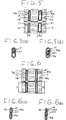
- FIG. 4 and 5 illustrate a first embodiment of the invention.
- a plurality of parallel flat tubes 11 and a plurality of parallel flat tube 31 are disposed between upper tank 14 and lower tank 15.
- the upstream flat tubes 11 are connected in fluid communication with inlet chamber 17 of upper tank 14, and the downstream flat tubes 31 are connected in fluid communication with outlet chamber 18 of upper tank 14.
- Corrugated fin units 12 are respectively positioned between two flat tubes 11 and two flat tubes 31.
- Each flat tubes 31 has a metal core 31a which is made of aluminium alloy with cladding linings 31 for preventing the pitting of flat tubes 31 such that cladding 31 functions as sacrificial metal for the core metal.
- Each tube 31 includes at least one fluid passageway therein and has a cross section with a width B which is larger than the width A of each flat tube 11 in the direction of the width of the heat exchange core 13.
- the depth of each flat tube 31 is identical to that of each flat tube 11.
- the passage cross sectional area of each flat tube 31 is larger than for the flat tubes 11.
- FIG. 6 illustrates a second embodiment of the invention.
- Flat tubes 41 have a metal core 41a which is made of aluminum alloy with cladding linings 41 for preventing the pitting of the flat tubes 31, the cladding 41 functioning as sacrificial metal for the core metal.
- Depth D of flat tubes 41 are larger than depth C of flat tubes 11.
- the thickness of flat tubes 41 are identical to that of flat tubes 11. Therefore, the passage cross sectional area of tubes 41 is larger than that of flat tubes 11 as in the first embodiment. Both the function and effect of this embodiment are almost same as the function and the effects of a first embodiment so that explanations thereof are omitted.
- the interior space 26 or tube 41 may be divided by a plurality of parallel wall portions 411 into a corresponding plurality of essentially parallel passages through which coolant fluid flows.
- FIG. 7 and 8 illustrates a third embodiment of the invention.
- Filter 23 is disposed in the center of chamber 21 of lower tank 15 and mechanically fixed to the inner surface of chamber 21 so that the chamber 21 is substantially partitioned into two chambers by filter 23.
- filter 23 is made of a porous material, such as metal or plastics, and filters the corrosion products which are grown in upstream flat tubes 11 leading from inlet chamber 17 of upper tank 14 without flowing into downstream flat tubes 11 which lead to outlet chamber 18 of upper tank 14. Thereby, the cooling medium, which does not contain corrosion products, passes through the downstream flat tubes 11 leading to outlet chamber 18 of upper tank 14.
- Filter 23 may be fixed to the inner surface of chamber 21 so as to be exchangeable.
- filter 23 may be designed to function, without impairing the heat exchanger until its area is clogged by 50%. Therefore, even if the corrosion products grow in the upstream flat tubes 11 and flow into chamber 21 of lower tank 15, flat tubes 31 will not be clogged by the corrosion products. As a result, the heat exchanging efficiency is not decreased in long service.
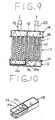
- FIG. 9 and 10 illustrate a fourth embodiment of the invention.
- Filter 24 includes first filter portion 24a and second filter portion 24b thereof.
- First filter portion 24a is mechanically connected to the inner surface of chamber 21 of lower tank 15 in parallel with flat tubes 11.
- Second filter portion 24b is extending from first filter portion 24a in parallel with the bottom surface of lower tank 15 and connected to the side surface of chamber 21 of lower tank 15.
- the surface area which can filter the corrosion products is wider than that of the third embodiment.
- the filtering ability is increased in comparison with the third embodiment.
Landscapes
- Engineering & Computer Science (AREA)
- Physics & Mathematics (AREA)
- Thermal Sciences (AREA)
- Mechanical Engineering (AREA)
- General Engineering & Computer Science (AREA)
- Heat-Exchange Devices With Radiators And Conduit Assemblies (AREA)
Applications Claiming Priority (2)
| Application Number | Priority Date | Filing Date | Title |
|---|---|---|---|
| JP3648193U JP2603450Y2 (ja) | 1993-07-02 | 1993-07-02 | 車両用熱交換器 |
| JP36481/93U | 1993-07-02 |
Publications (3)
| Publication Number | Publication Date |
|---|---|
| EP0632246A2 true EP0632246A2 (fr) | 1995-01-04 |
| EP0632246A3 EP0632246A3 (fr) | 1995-04-12 |
| EP0632246B1 EP0632246B1 (fr) | 1998-05-06 |
Family
ID=12471016
Family Applications (1)
| Application Number | Title | Priority Date | Filing Date |
|---|---|---|---|
| EP19940304576 Expired - Lifetime EP0632246B1 (fr) | 1993-07-02 | 1994-06-23 | Echangeur de chaleur |
Country Status (3)
| Country | Link |
|---|---|
| EP (1) | EP0632246B1 (fr) |
| JP (1) | JP2603450Y2 (fr) |
| DE (1) | DE69410022T2 (fr) |
Cited By (8)
| Publication number | Priority date | Publication date | Assignee | Title |
|---|---|---|---|---|
| DE19814827A1 (de) * | 1998-04-02 | 1999-10-07 | Behr Gmbh & Co | Wärmeübertrager für ein Kraftfahrzeug |
| EP0855567A3 (fr) * | 1997-01-24 | 2000-01-12 | Modine Manufacturing Company | Evaporateur/condenseur pour pompe à chaleur |
| US6341648B1 (en) * | 1997-04-23 | 2002-01-29 | Denso Corporation | Heat exchanger having heat-exchanging core portion divided into plural core portions |
| WO2004099695A1 (fr) * | 2003-04-30 | 2004-11-18 | Valeo Inc. | Echangeur thermique |
| WO2007124484A2 (fr) * | 2006-04-21 | 2007-11-01 | Parker-Hannifin Corporation | Réservoir à écoulement croisé intégré |
| DE102006035993A1 (de) * | 2006-08-02 | 2008-02-07 | Behr Gmbh & Co. Kg | Kraftfahrzeug-Klimaanlage und Wärmeübertrager, insbesondere Heizkörper, für eine Kraftfahrzeug-Klimaanlage |
| CN102735077A (zh) * | 2012-07-24 | 2012-10-17 | 天津商业大学 | 换热管内径变化的高效壳管式换热器 |
| FR3007513A1 (fr) * | 2013-06-24 | 2014-12-26 | Peugeot Citroen Automobiles Sa | Echangeur de chaleur equipant une ligne d'arrivee d'air d'un moteur a combustion interne |
Families Citing this family (1)
| Publication number | Priority date | Publication date | Assignee | Title |
|---|---|---|---|---|
| BR102013014855B1 (pt) * | 2013-06-13 | 2020-12-01 | Valeo Sistemas Automotivos Ltda | trocador de calor para veículo |
Citations (3)
| Publication number | Priority date | Publication date | Assignee | Title |
|---|---|---|---|---|
| US4387764A (en) * | 1981-12-03 | 1983-06-14 | Felt Products Mfg. Co. | Gasket screening assembly for an internal combustion engine having an auxiliary oil cooler |
| US4645000A (en) * | 1986-04-21 | 1987-02-24 | General Motors Corporation | Tube and fin heat exchanger |
| US5107921A (en) * | 1989-05-19 | 1992-04-28 | Tsai Frank W | Multi-mode heat exchanger |
-
1993
- 1993-07-02 JP JP3648193U patent/JP2603450Y2/ja not_active Expired - Lifetime
-
1994
- 1994-06-23 EP EP19940304576 patent/EP0632246B1/fr not_active Expired - Lifetime
- 1994-06-23 DE DE1994610022 patent/DE69410022T2/de not_active Expired - Fee Related
Patent Citations (3)
| Publication number | Priority date | Publication date | Assignee | Title |
|---|---|---|---|---|
| US4387764A (en) * | 1981-12-03 | 1983-06-14 | Felt Products Mfg. Co. | Gasket screening assembly for an internal combustion engine having an auxiliary oil cooler |
| US4645000A (en) * | 1986-04-21 | 1987-02-24 | General Motors Corporation | Tube and fin heat exchanger |
| US5107921A (en) * | 1989-05-19 | 1992-04-28 | Tsai Frank W | Multi-mode heat exchanger |
Cited By (13)
| Publication number | Priority date | Publication date | Assignee | Title |
|---|---|---|---|---|
| EP0855567A3 (fr) * | 1997-01-24 | 2000-01-12 | Modine Manufacturing Company | Evaporateur/condenseur pour pompe à chaleur |
| US6341648B1 (en) * | 1997-04-23 | 2002-01-29 | Denso Corporation | Heat exchanger having heat-exchanging core portion divided into plural core portions |
| DE19814827A1 (de) * | 1998-04-02 | 1999-10-07 | Behr Gmbh & Co | Wärmeübertrager für ein Kraftfahrzeug |
| DE19814827B4 (de) * | 1998-04-02 | 2008-11-13 | Behr Gmbh & Co. Kg | Wärmeübertrager für ein Kraftfahrzeug |
| US7337832B2 (en) | 2003-04-30 | 2008-03-04 | Valeo, Inc. | Heat exchanger |
| WO2004099695A1 (fr) * | 2003-04-30 | 2004-11-18 | Valeo Inc. | Echangeur thermique |
| US8256746B2 (en) | 2006-04-21 | 2012-09-04 | Parker-Hannifin Corporation | Integrated cross-flow reservoir |
| WO2007124484A3 (fr) * | 2006-04-21 | 2008-01-17 | Parker Hannifin Corp | Réservoir à écoulement croisé intégré |
| WO2007124484A2 (fr) * | 2006-04-21 | 2007-11-01 | Parker-Hannifin Corporation | Réservoir à écoulement croisé intégré |
| DE102006035993A1 (de) * | 2006-08-02 | 2008-02-07 | Behr Gmbh & Co. Kg | Kraftfahrzeug-Klimaanlage und Wärmeübertrager, insbesondere Heizkörper, für eine Kraftfahrzeug-Klimaanlage |
| CN102735077A (zh) * | 2012-07-24 | 2012-10-17 | 天津商业大学 | 换热管内径变化的高效壳管式换热器 |
| FR3007513A1 (fr) * | 2013-06-24 | 2014-12-26 | Peugeot Citroen Automobiles Sa | Echangeur de chaleur equipant une ligne d'arrivee d'air d'un moteur a combustion interne |
| EP2818822A1 (fr) * | 2013-06-24 | 2014-12-31 | Peugeot Citroën Automobiles Sa | Echangeur de chaleur équipant une ligne d'arrivée d'air d'un moteur à combustion interne |
Also Published As
| Publication number | Publication date |
|---|---|
| JP2603450Y2 (ja) | 2000-03-13 |
| JPH0712760U (ja) | 1995-03-03 |
| EP0632246B1 (fr) | 1998-05-06 |
| DE69410022T2 (de) | 1998-10-22 |
| DE69410022D1 (de) | 1998-06-10 |
| EP0632246A3 (fr) | 1995-04-12 |
Similar Documents
| Publication | Publication Date | Title |
|---|---|---|
| JP3810875B2 (ja) | 一体型熱交換器 | |
| EP0710811B2 (fr) | Un système de climatisation pour véhicule | |
| EP1172623B1 (fr) | Echangeur de chaleur et tube associé | |
| US6904963B2 (en) | Heat exchanger | |
| US7527087B2 (en) | Heat exchanger | |
| USRE35655E (en) | Condenser for use in a car cooling system | |
| AU656464B2 (en) | High pressure, long life, aluminum heat exchanger construction | |
| US4958681A (en) | Heat exchanger with bypass channel louvered fins | |
| US20050269066A1 (en) | Heat exchanger | |
| US20050061489A1 (en) | Integrated multi-function return tube for combo heat exchangers | |
| JPS61202084A (ja) | 熱交換器 | |
| US6283200B1 (en) | Heat exchanger having header tank increased in volume in the vicinity of pipe connected thereto | |
| US20070131397A1 (en) | Coolant radiator for a motor vehicle | |
| US5246064A (en) | Condenser for use in a car cooling system | |
| KR20140110968A (ko) | 내부 유동 변경 부재 및 외부 챔버 조립체를 가지는 튜브형 구조물을 이용하는 열 교환기 | |
| EP0632246B1 (fr) | Echangeur de chaleur | |
| US5190100A (en) | Condenser for use in a car cooling system | |
| US7174953B2 (en) | Stacking-type, multi-flow, heat exchanger | |
| US20040050531A1 (en) | Heat exchanger | |
| US20070267187A1 (en) | Heat Exchanger | |
| JP3674120B2 (ja) | 熱交換器 | |
| GB2073395A (en) | A heat exchanger for cooling a high temperature fluid | |
| EP0889299B1 (fr) | Echangeur de chaleur avec construction à tuyau double | |
| US6378203B1 (en) | Method of making fluid heat exchanger | |
| JP4058824B2 (ja) | 複式熱交換器 |
Legal Events
| Date | Code | Title | Description |
|---|---|---|---|
| PUAI | Public reference made under article 153(3) epc to a published international application that has entered the european phase |
Free format text: ORIGINAL CODE: 0009012 |
|
| AK | Designated contracting states |
Kind code of ref document: A2 Designated state(s): DE FR GB IT SE |
|
| PUAL | Search report despatched |
Free format text: ORIGINAL CODE: 0009013 |
|
| AK | Designated contracting states |
Kind code of ref document: A3 Designated state(s): DE FR GB IT SE |
|
| 17P | Request for examination filed |
Effective date: 19950922 |
|
| 17Q | First examination report despatched |
Effective date: 19960904 |
|
| GRAG | Despatch of communication of intention to grant |
Free format text: ORIGINAL CODE: EPIDOS AGRA |
|
| GRAG | Despatch of communication of intention to grant |
Free format text: ORIGINAL CODE: EPIDOS AGRA |
|
| GRAH | Despatch of communication of intention to grant a patent |
Free format text: ORIGINAL CODE: EPIDOS IGRA |
|
| GRAH | Despatch of communication of intention to grant a patent |
Free format text: ORIGINAL CODE: EPIDOS IGRA |
|
| GRAA | (expected) grant |
Free format text: ORIGINAL CODE: 0009210 |
|
| STAA | Information on the status of an ep patent application or granted ep patent |
Free format text: STATUS: THE PATENT HAS BEEN GRANTED |
|
| AK | Designated contracting states |
Kind code of ref document: B1 Designated state(s): DE FR GB IT SE |
|
| ET | Fr: translation filed | ||
| ITF | It: translation for a ep patent filed | ||
| REF | Corresponds to: |
Ref document number: 69410022 Country of ref document: DE Date of ref document: 19980610 |
|
| PLBE | No opposition filed within time limit |
Free format text: ORIGINAL CODE: 0009261 |
|
| PGFP | Annual fee paid to national office [announced via postgrant information from national office to epo] |
Ref country code: SE Payment date: 19990414 Year of fee payment: 6 |
|
| 26N | No opposition filed | ||
| PGFP | Annual fee paid to national office [announced via postgrant information from national office to epo] |
Ref country code: FR Payment date: 19990610 Year of fee payment: 6 |
|
| PGFP | Annual fee paid to national office [announced via postgrant information from national office to epo] |
Ref country code: GB Payment date: 19990623 Year of fee payment: 6 |
|
| PGFP | Annual fee paid to national office [announced via postgrant information from national office to epo] |
Ref country code: DE Payment date: 19990626 Year of fee payment: 6 |
|
| PG25 | Lapsed in a contracting state [announced via postgrant information from national office to epo] |
Ref country code: GB Free format text: LAPSE BECAUSE OF NON-PAYMENT OF DUE FEES Effective date: 20000623 |
|
| PG25 | Lapsed in a contracting state [announced via postgrant information from national office to epo] |
Ref country code: SE Free format text: LAPSE BECAUSE OF NON-PAYMENT OF DUE FEES Effective date: 20000624 |
|
| GBPC | Gb: european patent ceased through non-payment of renewal fee |
Effective date: 20000623 |
|
| EUG | Se: european patent has lapsed |
Ref document number: 94304576.5 |
|
| PG25 | Lapsed in a contracting state [announced via postgrant information from national office to epo] |
Ref country code: FR Free format text: LAPSE BECAUSE OF NON-PAYMENT OF DUE FEES Effective date: 20010228 |
|
| REG | Reference to a national code |
Ref country code: FR Ref legal event code: ST |
|
| PG25 | Lapsed in a contracting state [announced via postgrant information from national office to epo] |
Ref country code: DE Free format text: LAPSE BECAUSE OF NON-PAYMENT OF DUE FEES Effective date: 20010403 |
|
| PG25 | Lapsed in a contracting state [announced via postgrant information from national office to epo] |
Ref country code: IT Free format text: LAPSE BECAUSE OF NON-PAYMENT OF DUE FEES Effective date: 20050623 |