EP0630966A1 - Installation perfectionnée de fermentation anaérobie de matières organiques - Google Patents
Installation perfectionnée de fermentation anaérobie de matières organiques Download PDFInfo
- Publication number
- EP0630966A1 EP0630966A1 EP19940401383 EP94401383A EP0630966A1 EP 0630966 A1 EP0630966 A1 EP 0630966A1 EP 19940401383 EP19940401383 EP 19940401383 EP 94401383 A EP94401383 A EP 94401383A EP 0630966 A1 EP0630966 A1 EP 0630966A1
- Authority
- EP
- European Patent Office
- Prior art keywords
- fermenter
- nozzles
- wall
- diameter
- biogas
- Prior art date
- Legal status (The legal status is an assumption and is not a legal conclusion. Google has not performed a legal analysis and makes no representation as to the accuracy of the status listed.)
- Ceased
Links
Images
Classifications
-
- C—CHEMISTRY; METALLURGY
- C02—TREATMENT OF WATER, WASTE WATER, SEWAGE, OR SLUDGE
- C02F—TREATMENT OF WATER, WASTE WATER, SEWAGE, OR SLUDGE
- C02F3/00—Biological treatment of water, waste water, or sewage
- C02F3/28—Anaerobic digestion processes
-
- C—CHEMISTRY; METALLURGY
- C12—BIOCHEMISTRY; BEER; SPIRITS; WINE; VINEGAR; MICROBIOLOGY; ENZYMOLOGY; MUTATION OR GENETIC ENGINEERING
- C12M—APPARATUS FOR ENZYMOLOGY OR MICROBIOLOGY; APPARATUS FOR CULTURING MICROORGANISMS FOR PRODUCING BIOMASS, FOR GROWING CELLS OR FOR OBTAINING FERMENTATION OR METABOLIC PRODUCTS, i.e. BIOREACTORS OR FERMENTERS
- C12M21/00—Bioreactors or fermenters specially adapted for specific uses
- C12M21/04—Bioreactors or fermenters specially adapted for specific uses for producing gas, e.g. biogas
-
- C—CHEMISTRY; METALLURGY
- C12—BIOCHEMISTRY; BEER; SPIRITS; WINE; VINEGAR; MICROBIOLOGY; ENZYMOLOGY; MUTATION OR GENETIC ENGINEERING
- C12M—APPARATUS FOR ENZYMOLOGY OR MICROBIOLOGY; APPARATUS FOR CULTURING MICROORGANISMS FOR PRODUCING BIOMASS, FOR GROWING CELLS OR FOR OBTAINING FERMENTATION OR METABOLIC PRODUCTS, i.e. BIOREACTORS OR FERMENTERS
- C12M29/00—Means for introduction, extraction or recirculation of materials, e.g. pumps
- C12M29/06—Nozzles; Sprayers; Spargers; Diffusers
-
- C—CHEMISTRY; METALLURGY
- C12—BIOCHEMISTRY; BEER; SPIRITS; WINE; VINEGAR; MICROBIOLOGY; ENZYMOLOGY; MUTATION OR GENETIC ENGINEERING
- C12M—APPARATUS FOR ENZYMOLOGY OR MICROBIOLOGY; APPARATUS FOR CULTURING MICROORGANISMS FOR PRODUCING BIOMASS, FOR GROWING CELLS OR FOR OBTAINING FERMENTATION OR METABOLIC PRODUCTS, i.e. BIOREACTORS OR FERMENTERS
- C12M29/00—Means for introduction, extraction or recirculation of materials, e.g. pumps
- C12M29/14—Pressurized fluid
-
- C—CHEMISTRY; METALLURGY
- C12—BIOCHEMISTRY; BEER; SPIRITS; WINE; VINEGAR; MICROBIOLOGY; ENZYMOLOGY; MUTATION OR GENETIC ENGINEERING
- C12M—APPARATUS FOR ENZYMOLOGY OR MICROBIOLOGY; APPARATUS FOR CULTURING MICROORGANISMS FOR PRODUCING BIOMASS, FOR GROWING CELLS OR FOR OBTAINING FERMENTATION OR METABOLIC PRODUCTS, i.e. BIOREACTORS OR FERMENTERS
- C12M29/00—Means for introduction, extraction or recirculation of materials, e.g. pumps
- C12M29/24—Recirculation of gas
-
- Y—GENERAL TAGGING OF NEW TECHNOLOGICAL DEVELOPMENTS; GENERAL TAGGING OF CROSS-SECTIONAL TECHNOLOGIES SPANNING OVER SEVERAL SECTIONS OF THE IPC; TECHNICAL SUBJECTS COVERED BY FORMER USPC CROSS-REFERENCE ART COLLECTIONS [XRACs] AND DIGESTS
- Y02—TECHNOLOGIES OR APPLICATIONS FOR MITIGATION OR ADAPTATION AGAINST CLIMATE CHANGE
- Y02E—REDUCTION OF GREENHOUSE GAS [GHG] EMISSIONS, RELATED TO ENERGY GENERATION, TRANSMISSION OR DISTRIBUTION
- Y02E50/00—Technologies for the production of fuel of non-fossil origin
- Y02E50/30—Fuel from waste, e.g. synthetic alcohol or diesel
-
- Y—GENERAL TAGGING OF NEW TECHNOLOGICAL DEVELOPMENTS; GENERAL TAGGING OF CROSS-SECTIONAL TECHNOLOGIES SPANNING OVER SEVERAL SECTIONS OF THE IPC; TECHNICAL SUBJECTS COVERED BY FORMER USPC CROSS-REFERENCE ART COLLECTIONS [XRACs] AND DIGESTS
- Y02—TECHNOLOGIES OR APPLICATIONS FOR MITIGATION OR ADAPTATION AGAINST CLIMATE CHANGE
- Y02W—CLIMATE CHANGE MITIGATION TECHNOLOGIES RELATED TO WASTEWATER TREATMENT OR WASTE MANAGEMENT
- Y02W10/00—Technologies for wastewater treatment
- Y02W10/10—Biological treatment of water, waste water, or sewage
-
- Y—GENERAL TAGGING OF NEW TECHNOLOGICAL DEVELOPMENTS; GENERAL TAGGING OF CROSS-SECTIONAL TECHNOLOGIES SPANNING OVER SEVERAL SECTIONS OF THE IPC; TECHNICAL SUBJECTS COVERED BY FORMER USPC CROSS-REFERENCE ART COLLECTIONS [XRACs] AND DIGESTS
- Y10—TECHNICAL SUBJECTS COVERED BY FORMER USPC
- Y10S—TECHNICAL SUBJECTS COVERED BY FORMER USPC CROSS-REFERENCE ART COLLECTIONS [XRACs] AND DIGESTS
- Y10S435/00—Chemistry: molecular biology and microbiology
- Y10S435/813—Continuous fermentation
-
- Y—GENERAL TAGGING OF NEW TECHNOLOGICAL DEVELOPMENTS; GENERAL TAGGING OF CROSS-SECTIONAL TECHNOLOGIES SPANNING OVER SEVERAL SECTIONS OF THE IPC; TECHNICAL SUBJECTS COVERED BY FORMER USPC CROSS-REFERENCE ART COLLECTIONS [XRACs] AND DIGESTS
- Y10—TECHNICAL SUBJECTS COVERED BY FORMER USPC
- Y10S—TECHNICAL SUBJECTS COVERED BY FORMER USPC CROSS-REFERENCE ART COLLECTIONS [XRACs] AND DIGESTS
- Y10S435/00—Chemistry: molecular biology and microbiology
- Y10S435/818—Aeration or oxygen transfer technique
Definitions
- the present invention essentially relates to an improved installation for anaerobic fermentation of organic materials, for example from urban waste such as household waste.
- anaerobic fermentation facilities for organic materials essentially comprise a fermenter in which the organic materials are kept for a certain time in order to produce biogas in particular.
- the fermenter especially when it has a large volume, poses problems of flow of the materials it contains.
- the present invention achieves this goal.
- a fermenter where said materials stay for a certain time for the purpose of producing in particular biogas, characterized by a plurality of nozzles for pressure injection of biogas and / or other gaseous, liquid or more or less solid materials into the fermenter, which nozzles are distributed around the periphery of the fermenter in the same plane or in different planes, thereby improving the flow materials in the fermenter and its performance especially when it has a large volume.
- the injection nozzles integral with the wall of the fermenter are connected by means of a valve to at least one pipe in a ring surrounding the fermenter and itself connected to the minus a supply line for recycled biogas or another material.
- this installation is characterized in that the above-mentioned pipe forms two half-rings joined by only one of their ends so as to constitute a connection zone comprising two valves between which the above-mentioned supply line is connected.
- This installation is further characterized in that certain injection nozzles are implanted substantially normally on the wall of the fermenter, while other nozzles are implanted on the wall of the fermenter in directions not normal to said wall.
- the installation according to this invention is further characterized in that the aforementioned supply line for the half-rings connected to the nozzles is supplied with biogas by at least one capacity connected to a compressor.
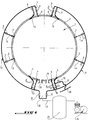
- Figure 1 is a schematic view in cross section of a fermenter equipped with the means according to this invention.
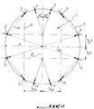
- Figure 2 is also a schematic view in cross section of the fermenter illustrating the position and orientation of the injection nozzles, according to an exemplary embodiment.
- an anaerobic fermentation installation consisting essentially of a fermenter or digester 1 into which materials can be introduced. organic which stay there a certain time and whose fermentation makes it possible to produce biogas.
- a plurality of nozzles 3, 4, 5 for pressure injection of biogas and / or other gaseous materials, liquids or more or less solid, are installed on the external wall 2 of the fermenter 1.
- nozzles 3 are located substantially normally on the wall 2 of the fermenter 1, while other nozzles, such as nozzles 4 and 5 are installed on the wall 2 of the fermenter 1 in non-normal directions to wall 2.
- the injection nozzles 3, 4, 5 integral with the wall 2 of the fermenter 1 are connected via a conduit 6 with valve 7 to a pipe in the form of two half crowns 8, 9 surrounding the fermenter 1.
- connection zone 10 provided with two valves 12. Between these two valves, is connected a pipe 11 for supplying biogas pressure recycled.
- the pipe 11 is connected to a capacity 13 which is itself supplied with biogas by a compressor 14.
- the capacity 6 can store biogas until the required pressure is obtained in the half-rings 8, 9 supplying gas to the injection nozzles 3, 4, 5, via the conduits 6.
- this material can also of course be injected into the fermenter 1 via the nozzles 3, 4, 5.
- Such material can be injected for example via a ring 30 independent of the pipeline 8, 9 and connected to a conduit 31 with valve 32 communicating with one or more nozzles such as 5.
- This solution can restore a momentary drift in the homogeneity of all of the material in the digester 1 and particularly in the internal peripheral areas of the digester.
- We can therefore use either a system with capacity 13 and compressor 14 for feeding, or another system, depending on the material to be injected into the digester to solve the problems of flow and transit of said material in the digester , especially when it has a large volume.
- the injection nozzles 3, 4, 5 may have a well-defined orientation as a function of the material injected by the nozzles and of the operating conditions, as will be described in detail later.
- valves 7 upstream of the injection nozzles 3, 4, 5 connected by the conduits 6 to the half-crowns 8, 9 can be controlled from an automaton or other programming device (not shown), according to an appropriate sequence and which may vary according to the viscosity of the fermentable material.
- Such a sequence can be carried out both when using recycled biogas as an injection material, and when using fresh organic material or materials at an intermediate level of degradation taken from another digester.
- the injection nozzles 3, 4, 5 will obviously be judiciously oriented so as to allow homogenization of all of the material in fermentation in the digester 1.
- their number may be arbitrary, and they may be distributed around the periphery of the digester 1 along the same plane, or according to different planes over the entire height of the digester. That is to say, in the latter case, that half-rings 8, 9 assembled as explained above could be installed at several levels along the height of the fermenter 1, it being understood that the provision of half-rings with nozzles associated injection in the lower part of fermenter 1 remains the most important, since this is where the risks of sedimentation are most marked.
- FIG. 2 clearly illustrates an exemplary embodiment of implantation of the injection nozzles 3, 4, 5 on the wall 2 of the fermenter 1, and this in a plane of straight cross section of said fermenter.
- the injection nozzles 3, 4, 5 form three groups of nozzles located and oriented in the following manner.
- the first group consists of four nozzles 3 which are located on the wall 2 of the digester 1 symmetrically on either side of a first diameter 20 of the fermenter and at a distance from this diameter 20 equal to one third of the radius R of the fermenter. As can be seen in the figure, the axis of the nozzles 3 is oriented radially.
- the second group consists of four nozzles 4 which are located on the wall 2 symmetrically on either side of a second diameter 21 of the fermenter, perpendicular to the first diameter 20.
- the axis of these nozzles forms an angle of 15 ° with the second diameter centrifugal direction 20.
- the third group of nozzles consists of four nozzles 5 located on the wall 2 of the fermenter at the point of intersection of a straight line 22 mediating the radius of the first diameter 20.
- l orientation or the axis of each nozzle 5 coincides with the cord 23 of the wall arc 2 connecting a nozzle 5 to a neighboring nozzle 3 of the first group.
- twelve injection nozzles are used, four of which, namely the nozzles 3 are oriented radially, while the other eight nozzles are more or less inclined.
- the fermenter 1 can be a large volume fermenter and include, as shown in 24 and 25 on the Figure 1, a material inlet and outlet, as well as a partition (not shown) coinciding with the second diameter 21, taking root on the inner periphery of the fermenter 1 between the inlet and the outlet 24, 25 and s' extending over only part of the second diameter 21.
- the position and orientation of the injection nozzles can be arbitrary and depend on the dimensions of the fermenter and the nature of the materials to be treated.
- the number of half-crowns with injection nozzles can be arbitrary, as can the type of valves used upstream of the injections, provided that the opening, the opening time and the closing of these valves can be controlled in any sequence by a programmable controller or the like.
- the injection nozzles will also be of any suitable design and able to allow the injection of gases, liquids or even more or less solid materials.
Landscapes
- Life Sciences & Earth Sciences (AREA)
- Engineering & Computer Science (AREA)
- Chemical & Material Sciences (AREA)
- Health & Medical Sciences (AREA)
- Organic Chemistry (AREA)
- Bioinformatics & Cheminformatics (AREA)
- Zoology (AREA)
- Wood Science & Technology (AREA)
- Microbiology (AREA)
- Genetics & Genomics (AREA)
- General Health & Medical Sciences (AREA)
- General Engineering & Computer Science (AREA)
- Biotechnology (AREA)
- Sustainable Development (AREA)
- Biomedical Technology (AREA)
- Biochemistry (AREA)
- Molecular Biology (AREA)
- Water Supply & Treatment (AREA)
- Hydrology & Water Resources (AREA)
- Biodiversity & Conservation Biology (AREA)
- General Chemical & Material Sciences (AREA)
- Environmental & Geological Engineering (AREA)
- Oil, Petroleum & Natural Gas (AREA)
- Processing Of Solid Wastes (AREA)
- Treatment Of Sludge (AREA)
- Apparatus Associated With Microorganisms And Enzymes (AREA)
Applications Claiming Priority (2)
| Application Number | Priority Date | Filing Date | Title |
|---|---|---|---|
| FR9307648A FR2706905B1 (enExample) | 1993-06-23 | 1993-06-23 | |
| FR9307648 | 1993-06-23 |
Publications (1)
| Publication Number | Publication Date |
|---|---|
| EP0630966A1 true EP0630966A1 (fr) | 1994-12-28 |
Family
ID=9448480
Family Applications (1)
| Application Number | Title | Priority Date | Filing Date |
|---|---|---|---|
| EP19940401383 Ceased EP0630966A1 (fr) | 1993-06-23 | 1994-06-20 | Installation perfectionnée de fermentation anaérobie de matières organiques |
Country Status (4)
| Country | Link |
|---|---|
| US (1) | US5523234A (enExample) |
| EP (1) | EP0630966A1 (enExample) |
| JP (1) | JPH07163332A (enExample) |
| FR (1) | FR2706905B1 (enExample) |
Cited By (2)
| Publication number | Priority date | Publication date | Assignee | Title |
|---|---|---|---|---|
| EP1811015A1 (de) * | 2006-01-20 | 2007-07-25 | Eckard, Horst K. | Einleitung von Biogas in einen Fermenter |
| WO2008093044A1 (en) * | 2007-02-02 | 2008-08-07 | Enviro Control Limited | Anaerobic digester |
Families Citing this family (4)
| Publication number | Priority date | Publication date | Assignee | Title |
|---|---|---|---|---|
| AU2009266304B2 (en) | 2008-07-02 | 2014-11-27 | Ciris Energy, Inc. | Method for optimizing in-situ bioconversion of carbon-bearing formations |
| SG10201408469TA (en) * | 2009-12-18 | 2015-02-27 | Ciris Energy Inc | Biogasification of coal to methane and other useful products |
| HUE043165T2 (hu) * | 2011-09-30 | 2019-08-28 | Landia As | Gázkeverõ berendezés és módszer |
| CN111304065A (zh) * | 2020-04-02 | 2020-06-19 | 上海环境工程设计研究院有限公司 | 一种基于气搅拌的果蔬湿式厌氧发酵装置及其工作方法 |
Citations (4)
| Publication number | Priority date | Publication date | Assignee | Title |
|---|---|---|---|---|
| FR914808A (fr) * | 1944-08-31 | 1946-10-18 | Digesteur industriel à marche continue pour ordures des villes, boues d'égouts et toutes matières organiques | |
| GB2189237A (en) * | 1986-03-20 | 1987-10-21 | Wessex Water Authority | Anaerobic digester |
| EP0250998A2 (de) * | 1986-06-26 | 1988-01-07 | Bayer Ag | Vorrichtung und Verfahren zur Kultivierung von immobilisierten Mikroorganismen |
| JPS6384693A (ja) * | 1986-09-26 | 1988-04-15 | Ishikawajima Harima Heavy Ind Co Ltd | 流動床式汚水処理装置 |
Family Cites Families (1)
| Publication number | Priority date | Publication date | Assignee | Title |
|---|---|---|---|---|
| US4036699A (en) * | 1976-02-02 | 1977-07-19 | Phillips Petroleum Company | Fermentation apparatus and method |
-
1993
- 1993-06-23 FR FR9307648A patent/FR2706905B1/fr not_active Expired - Fee Related
-
1994
- 1994-06-17 US US08/262,084 patent/US5523234A/en not_active Expired - Fee Related
- 1994-06-20 EP EP19940401383 patent/EP0630966A1/fr not_active Ceased
- 1994-06-20 JP JP13738194A patent/JPH07163332A/ja active Pending
Patent Citations (4)
| Publication number | Priority date | Publication date | Assignee | Title |
|---|---|---|---|---|
| FR914808A (fr) * | 1944-08-31 | 1946-10-18 | Digesteur industriel à marche continue pour ordures des villes, boues d'égouts et toutes matières organiques | |
| GB2189237A (en) * | 1986-03-20 | 1987-10-21 | Wessex Water Authority | Anaerobic digester |
| EP0250998A2 (de) * | 1986-06-26 | 1988-01-07 | Bayer Ag | Vorrichtung und Verfahren zur Kultivierung von immobilisierten Mikroorganismen |
| JPS6384693A (ja) * | 1986-09-26 | 1988-04-15 | Ishikawajima Harima Heavy Ind Co Ltd | 流動床式汚水処理装置 |
Non-Patent Citations (1)
| Title |
|---|
| DATABASE WPI Section Ch Week 8821, Derwent World Patents Index; Class D04, AN 88-143477 * |
Cited By (3)
| Publication number | Priority date | Publication date | Assignee | Title |
|---|---|---|---|---|
| EP1811015A1 (de) * | 2006-01-20 | 2007-07-25 | Eckard, Horst K. | Einleitung von Biogas in einen Fermenter |
| WO2008093044A1 (en) * | 2007-02-02 | 2008-08-07 | Enviro Control Limited | Anaerobic digester |
| GB2448113A (en) * | 2007-02-02 | 2008-10-08 | Enviro Control Ltd | Anaerobic digester |
Also Published As
| Publication number | Publication date |
|---|---|
| US5523234A (en) | 1996-06-04 |
| FR2706905A1 (enExample) | 1994-12-30 |
| JPH07163332A (ja) | 1995-06-27 |
| FR2706905B1 (enExample) | 1995-08-11 |
Similar Documents
| Publication | Publication Date | Title |
|---|---|---|
| EP0312428B1 (fr) | Dispositif d'injection d'une charge d'hydrocarbures dans un réacteur de craquage catalytique | |
| EP0298872B1 (fr) | Procédé et dispositif de répartition d'un volume primaire de fluide en un nombre déterminé de volumes secondaires présentant une relation prédéfinie entre eux | |
| CA1280227C (fr) | Reacteur a lit fluidise pour traitement biologique de l'eau | |
| WO1992017278A1 (fr) | Cyclone a double effet d'extraction | |
| WO1994027038A1 (fr) | Systeme d'injection a fentes concentriques et elements d'injection associes | |
| EP0630966A1 (fr) | Installation perfectionnée de fermentation anaérobie de matières organiques | |
| EP1032464B1 (fr) | Distributeur de liquide pour colonne de distillation non verticale, et colonne de distillation ainsi equipee | |
| WO2003039733A1 (fr) | Dispositif de distribution d'un melange polyphasique sur un lit de solide granulaire comportant un element brise jet poreux a rebords | |
| WO2012076761A1 (fr) | Dispositif de remplissage d'un recipient avec des particules solides comportant un diaphragme | |
| EP2162207B1 (fr) | Enceinte contenant un lit granulaire et une distribution d'une phase gazeuse et d'une phase liquide circulant en un écoulement ascendant dans cette enceinte. | |
| EP1152967B1 (fr) | Dispositif de dispersion d'un materiau solide divise a l'interieur d'un recipient | |
| CA1285374C (fr) | Dispositif pour l'alimentation des ouvertures d'une grille de fluidisation en gaz de decolmatage | |
| FR2666094A1 (fr) | Bouteille de culture en masse de cellules et procede pour son assemblage. | |
| FR2651216A1 (fr) | Dispositif pour le transport hydraulique de materiaux pulverulents. | |
| FR2733700A1 (fr) | Enceintes avec soutirage ameliore des particules solides | |
| EP3820601B1 (fr) | Dispositif de distribution d'un fluide, apte a etre dispose dans un reacteur comprenant un lit catalytique fixe | |
| FR2766386A1 (fr) | Dispositif de dispersion d'un materiau solide divise a l'interieur d'un recipient | |
| FR2629555A1 (fr) | Vanne numerique | |
| EP2086891B1 (fr) | Procédé et installation de traitement anaérobie de matières à concentration de matière sèche élevée | |
| FR2533838A1 (fr) | Buse de pulverisation | |
| FR2874945A1 (fr) | Boite de repartition d'effluent | |
| FR2796566A1 (fr) | Carter de filtre pour fluide et filtre pour fluide pourvu d'un tel carter | |
| FR2700605A1 (fr) | Dispositif d'injection de boues dans un incinérateur de déchets. | |
| FR2995757A1 (fr) | Distributeur d'irrigation a debit autoregule et son utilisation | |
| CA3176311A1 (fr) | Systeme et procede de recirculation pour un decanteur, notamment un clarificateur d'une station d'epuration |
Legal Events
| Date | Code | Title | Description |
|---|---|---|---|
| PUAI | Public reference made under article 153(3) epc to a published international application that has entered the european phase |
Free format text: ORIGINAL CODE: 0009012 |
|
| AK | Designated contracting states |
Kind code of ref document: A1 Designated state(s): AT BE CH DE DK ES GB GR IE IT LI LU MC NL PT SE |
|
| 17P | Request for examination filed |
Effective date: 19950415 |
|
| RAP1 | Party data changed (applicant data changed or rights of an application transferred) |
Owner name: L. & C. STEINMUELLER GMBH |
|
| 17Q | First examination report despatched |
Effective date: 19980715 |
|
| GRAG | Despatch of communication of intention to grant |
Free format text: ORIGINAL CODE: EPIDOS AGRA |
|
| STAA | Information on the status of an ep patent application or granted ep patent |
Free format text: STATUS: THE APPLICATION HAS BEEN REFUSED |
|
| 18R | Application refused |
Effective date: 19990904 |