EP0630780A1 - Circuit device for flashing light - Google Patents
Circuit device for flashing light Download PDFInfo
- Publication number
- EP0630780A1 EP0630780A1 EP94107196A EP94107196A EP0630780A1 EP 0630780 A1 EP0630780 A1 EP 0630780A1 EP 94107196 A EP94107196 A EP 94107196A EP 94107196 A EP94107196 A EP 94107196A EP 0630780 A1 EP0630780 A1 EP 0630780A1
- Authority
- EP
- European Patent Office
- Prior art keywords
- flashing
- trailer
- circuit
- towing vehicle
- circuit arrangement
- Prior art date
- Legal status (The legal status is an assumption and is not a legal conclusion. Google has not performed a legal analysis and makes no representation as to the accuracy of the status listed.)
- Withdrawn
Links
Images


Classifications
-
- B—PERFORMING OPERATIONS; TRANSPORTING
- B60—VEHICLES IN GENERAL
- B60Q—ARRANGEMENT OF SIGNALLING OR LIGHTING DEVICES, THE MOUNTING OR SUPPORTING THEREOF OR CIRCUITS THEREFOR, FOR VEHICLES IN GENERAL
- B60Q1/00—Arrangement of optical signalling or lighting devices, the mounting or supporting thereof or circuits therefor
- B60Q1/26—Arrangement of optical signalling or lighting devices, the mounting or supporting thereof or circuits therefor the devices being primarily intended to indicate the vehicle, or parts thereof, or to give signals, to other traffic
- B60Q1/34—Arrangement of optical signalling or lighting devices, the mounting or supporting thereof or circuits therefor the devices being primarily intended to indicate the vehicle, or parts thereof, or to give signals, to other traffic for indicating change of drive direction
- B60Q1/38—Arrangement of optical signalling or lighting devices, the mounting or supporting thereof or circuits therefor the devices being primarily intended to indicate the vehicle, or parts thereof, or to give signals, to other traffic for indicating change of drive direction using immovably-mounted light sources, e.g. fixed flashing lamps
Definitions
- the invention relates to a circuit arrangement for a turn signal system of a wagon train consisting of a towing vehicle and a trailer which can be electrically connected to the towing vehicle, with a blinking clock generator which is designed to operate at its clock output all the blinking lamps of the towing vehicle which are provided in each direction of travel and which have at least one control input over which the number of the provided in each direction of travel and monitored flashing lamps of the towing vehicle can be selected, and which drives a signal lamp to indicate the flashing cycle, the flashing clock signaling the failure of a controlled flashing lamp of the towing vehicle when the trailer is not electrically connected via an increased flashing frequency.
- a blinking clock generator which is designed to operate at its clock output all the blinking lamps of the towing vehicle which are provided in each direction of travel and which have at least one control input over which the number of the provided in each direction of travel and monitored flashing lamps of the towing vehicle can be selected, and which drives a signal lamp to indicate the flashing cycle, the flashing clock signaling the failure of
- the known circuit arrangements have a flashing clock generator, which can generally drive three flashing lamps in each direction of travel, and which has a control output at which the simultaneous operation of the corresponding flashing lamps of the towing vehicle and the trailer is indicated in each direction of travel. Two of these flashing lamps belong to the flashing light system of the towing vehicle and the third flashing lamp to the flashing light system of the trailer. All flashing lights are usually operated in parallel, so that the more flashing lights are connected, the greater the current flow from the flashing clock generator.
- the flashing clock generator drives three flashing lamps in each direction of travel. In this case, it outputs a signal at its control output called C2, via which a flashing light is usually operated with the flashing cycle and must be accommodated in the dashboard. On the basis of this indicator light, which flashes in the blinking cycle, the vehicle driver can recognize that all three blinking lamps are functional.
- the circuit arrangement has the usual signal lamp, which is also provided in the dashboard, and not only reflects the blinking cycle but also the direction indicator.
- the flashing clock generator drives only two flashing lamps per direction of travel, it is that one of the three flashing lamps per direction of travel has failed, or that no trailer is electrically connected, the flashing clock generator does not output any signal at its control output C2. However, the signal lamp continues to operate and shows the blinking cycle and the direction of travel.
- the blinking clock generator recognizes this from the changed current output and switches to a higher blinking frequency.
- the known flashing clock transmitters can thus be used universally; the respective flashing clock transmitters are matched to the conditions of the special towing vehicle by means of a fixed connection of the control inputs with voltage dividers.
- These flasher clocks are designed to drive two flasher lamps with a power consumption of 21 W each and several flasher lamps with lower power consumption in each direction of travel.
- flasher clock generators are usually only designed to operate two flasher lamps (plus a door flasher lamp, for example, with lower power consumption) in each direction of travel. So far, there are two options for converting a towing vehicle to trailer operation:
- the flasher clock generator provided for operating two flasher lamps per direction of travel is replaced by one which can operate three flasher lamps per direction of travel, as was already described at the beginning.
- the additional control lamp C2 must be installed in the driver's field of vision. Particularly in vehicles with airbags and similar safety devices, the retrofitting of this indicator light leads to lengthy and therefore cost-intensive work. In addition, especially in the case of small towing vehicles, it is often not possible to accommodate this additional indicator lamp in the dashboard.
- the flashing clock generator designed to operate two flashing lamps in each direction of travel in the vehicle and to operate either the rear flashing lamp of the towing vehicle or the flashing lamp of the trailer via a high-impedance driver circuit which does not additionally burden the flashing clock generator.
- the circuit arrangement required for this usually also includes an error detection circuit which monitors the flashing lamp operated in a high-resistance manner. If this third flashing lamp fails, which the flashing clock generator cannot recognize, then one of the two flashing lamps operated directly by the flashing clock generator is switched off by the flashing clock generator and also operated with high resistance. In this way, the failure of a flashing lamp is simulated for the flashing clock generator, which leads to the flashing clock generator switching over to the increased flashing frequency.
- this object is achieved in that the or each control input of the flashing clock is connected to switching means which, when the trailer is electrically connected, connects the or each control input in such a way that the flashing clock switches to the increased flashing frequency in the event of a controlled flashing lamp failure.
- the object underlying the invention is completely achieved in this way.
- the switching means provided according to the invention now influence the flashing clock generator via the control inputs, which are actually only intended for fixed wiring during assembly in the towing vehicle.
- the applicant has surprisingly found that by influencing the flashing clock generator via the control inputs, which is yet to be explained in more detail, a simple error display is possible.
- the switching means can include, for example, the error detection circuits mentioned above, so that they first recognize the failure of a controlled flashing lamp. If the flasher clock generator is equipped to operate two flasher lamps in the towing vehicle and an additional flasher lamp in the trailer for each direction of travel, this failure of a flasher lamp would initially not result in the flasher clock generator switching to the increased flashing frequency. Rather, this failure would only occur on the any existing control output is displayed. However, the control inputs are now connected via the switching means in such a way that the flashing clock generator is now switched to operate three flashing lamps in the towing vehicle and an additional flashing lamp in the trailer for each direction of travel.
- the flashing clock sensor detects an error and switches to the increased flashing frequency. It is of particular advantage here that the C2 indicator light can be dispensed with in the dashboard.
- the signal lamp for displaying the flashing clock which is present anyway is used by this "reversal" of the flashing clock for error display.
- the appropriate switching threshold in the flashing clock generator can be set so high by suitable wiring of the control inputs that it can also monitor three flashing lamps with a power of 21 W.
- the C2 control lamp can be dispensed with in the dashboard while converting a towing vehicle to trailer operation. It is only necessary to install a new flasher unit, which is operated via the new circuit arrangement in the manner just described. Compared to the measures mentioned at the beginning of the leakage current feed or the disconnection or connection of high-resistance flashing lamps, the new circuit arrangement has the further advantage that considerably fewer components are required. For example, the required relays can be completely dispensed with. The new circuit arrangement can also be installed in the production of new vehicles with the same advantages.
- the switching means when the trailer is electrically connected, connect the or each control input in such a way that the number of monitored flashing lamps is equal to the number of flashing lamps per direction of travel.
- This measure has the advantage that the switching means themselves no longer have to comprise error detection circuits, so that they can be constructed in a structurally simpler manner than is known from the prior art. At the moment when a trailer is electrically connected, this is communicated to the switching means by means of suitable measures, which then connect the flashing clock generator via the control inputs as if a larger number of flashing lamps were present in the towing vehicle itself. The flashing clock's ability to detect the failure of a lamp in the towing vehicle is thus used in two ways. Such measures are not known from the prior art, because up to now the C2 indicator light has been used in addition to provide additional information about the trailer's flashing lights, as described in detail above.
- the new circuit arrangement is thus extremely simple to set up, since it only requires an input on which the electrical connection of a trailer is "communicated” to it.
- the switching means connect the control inputs of the flashing clock so that it monitors all the flashing lights of the wagon train.
- the installation of the new circuit arrangement is also much easier than is known from the prior art discussed at the outset. If a towing vehicle is to be converted to trailer operation, all that now has to be changed is the flasher unit and the new one Circuit arrangement can be installed.
- the flasher unit and the external circuitry through the new circuit arrangement can also be designed monolithically as a single IC or as a printed circuit board, so that only the previous flasher unit has to be replaced by this new component.
- a trailer detection circuit which reports a trailer electrically connected to the towing vehicle on a trailer detection line.
- the advantage here is that the trailer is recognized automatically, so that the vehicle driver no longer has to flip an appropriate switch after coupling and electrically switching on the trailer. This also leads to a reduction in the number of components, since the additional switch is omitted.
- the trailer detection circuit is known per se from the prior art. In addition to querying the trailer mass, it can also derive its information by monitoring the current flow, for example using the switch for the brake light and / or parking light. An increased current flow indicates a connected trailer.
- the trailer detection circuit is connected to the control output of the flashing clock generator and recognizes an electrically connected trailer from the signals of the control output.
- Another advantage here is that the signal generated anyway on the control output is used to detect a trailer. This takes advantage of the fact that the control output only emits a signal when a trailer is actually electrically connected and the flashing light system of the wagon train is actuated accordingly.
- the measures known from the prior art of providing an additional trailer detection contact or a mass interrogation device for the trailer mass can thus be omitted. This also leads to a very low component requirement.
- the trailer detection circuit comprises a memory element which stores the first response of the control output and permanently reports on the trailer detection line.
- This measure is particularly advantageous under technical circuit conditions, because only one memory element must be provided, which is switched to a permanent state after the first response of the control output, from which it is only reset, for example, after the ignition switch has been opened.
- the storage element initially goes into a basic state in which it does not output a signal on the trailer detection line. If the factory direction switch is then actuated for the first time, the control output responds to what is stored by the storage element.
- a flip-flop can be connected to the control output in this way, the output of the flip-flop then being connected to the trailer detection line.
- control output is connected to an acoustic device.
- the additional control lamp in the dashboard can be dispensed with in the new circuit arrangement.
- the acoustic device is provided.
- the control output can now either give an acoustic signal each time it responds via the acoustic device, so that the vehicle driver is informed at all times about the functionality of all flashing lights in each direction of travel, or do so only once at the start of the journey. Since the driver knows that he is fully informed about the status of his flashing light system via the usual signal lamp, the additional acoustic signal can now be used to indicate to the driver at the start of the trip that the trailer has been correctly electrically connected to the towing vehicle. If the signal is missing, the driver must check the turn signal system right at the start of the journey.
- the new switching arrangement can be installed without having to carry out major assembly work on the towing vehicle.
- the new circuit arrangement comprises so few components that it can be manufactured very inexpensively.
- the assembly effort is negligible compared to the installation of the additional control lamp.
- the trailer detection circuit is connected to a reset device, via which the trailer detection line can be switched back.
- This measure is particularly advantageous if the driver decouples the trailer while the towing vehicle is running. If no reset device were now provided, the trailer detection circuit would still output the previously stored state of a connected trailer on the trailer detection line. When the travel direction switch was actuated, this would result in the switching means recognizing an error state and influencing the flashing clock generator accordingly.
- the reset device comprises a make contact.
- This make contact can be a pressure switch, which the driver briefly actuates after uncoupling the trailer in order to reset the trailer detection circuit. Compared to the installation of the C2 lamp to be installed in the driver's field of vision, this has the advantage that the pressure switch can be accommodated at any point, which leads to considerably easier installation conditions.
- the make contact can also be a door contact that is closed when the driver's door or the passenger's door is opened. If the driver or front passenger get out of the running towing vehicle to uncouple a trailer, this automatically leads to the trailer detection circuit being reset.
- the reset device comprises a measuring device for the current flow through selected lamps of the trailer and switches the trailer detection line back on as a function of the current flow.
- the trailer detection circuit is now reset by the measuring device.
- These selected lamps preferably include the brake light or the parking light.
- the reset device only has to be connected to the corresponding switch, for example for the brake light, by means of two cables, the measuring device being able to differentiate between states in which only the towing vehicle lamps or additionally the trailer lamps are controlled. After the trailer has been uncoupled, it is recognized when the first braking that there is no trailer. The reset device then outputs a reset signal to the trailer detection circuit.
- control output is connected to a locking circuit which, depending on the operation of the hazard warning system, decouples the control output from the trailer detection circuit.
- This measure is intended for flashing clock transmitters, which also output a C2 signal when the hazard warning system is operated without an electrically connected trailer, that is, when a total of four lamps are supplied by the flashing clock generator.
- These flasher clock generators cannot distinguish between the operation of three flasher lamps - towing vehicle + trailer - and the operation of four flasher lamps - no trailer, but hazard warning system of the towing vehicle switched on. Therefore, the operation of the Hazard warning system incorrectly occurring trailer detection can be prevented or reversed.
- the locking circuit is provided, which decouples the control output from the trailer detection circuit. In this way it is ensured that, when the hazard warning system is in operation, the control output of the trailer detection circuit does not switch to the state in which it reports an electrically connected trailer on its trailer detection line.
- the locking device has a measuring circuit for the lamp current emitted by the flashing clock generator.
- the advantage here is that the locking circuit itself detects whether the flashing clock operates three or four lamps.
- the control output is only decoupled from the trailer detection circuit if four lamps are operated.
- there are no problems here if only three lamps are in operation when the hazard warning system is in operation, because one of the lamps in the flashing system of the towing vehicle has failed. Actuating the hazard warning lights sets the trailer detection circuit accordingly, but the error message that would then occur during normal operation of the flashing lights system would occur anyway in at least one direction of travel.
- the stored trailer detection signal now causes the switching means to connect the flashing clock generator as if a trailer were switched on.
- the flashing clock generator now expects, for example, three times 21 W power consumption in each direction, ie two times 21 W from the towing vehicle and one time 21 W from the trailer.
- this measure even has the additional advantage that the defective lamp is then also displayed becomes when the direction switch switches two functioning lamps in the current switching state, although one of the lamps of the direction not currently selected is defective.
- the switching means comprise a voltage divider circuit which, depending on signals on the trailer detection line, connects different voltage dividers to the control inputs.
- This measure is also advantageous in terms of circuitry, because wiring the control inputs with different voltage dividers is the simplest way to influence the flashing clock generator in the desired manner.
- Two different voltage dividers are provided, one for the operating state with two monitored flashing lamps per direction of travel and one for the operating state with three monitored flashing lamps per direction of travel (trailer switched on), between which switching takes place by means of a relay or electronic switch depending on the trailer detection.
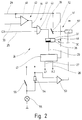
- FIG. 1 A circuit arrangement for a flashing light system, indicated at 11, of a wagon train is designated in FIG. 1 overall.
- the turn signal system 11 comprises three turn signals 12, 13, 14 in each direction of travel.
- the turn signals 12 and 13 are turn signals of the towing vehicle, while the turn signal lamp 14 is closed belongs to a trailer electrically connected to the towing vehicle, not shown, and is connected in parallel to the flashing lamps 12 and 13 via a plug shown at 15.
- the turn signal system 11 is only shown in FIG. 1 for one direction of travel, but the turn signals in the second direction of travel are connected accordingly.
- a flashing clock generator 17 is provided, which is connected via an ignition switch 18 labeled ZS to a supply voltage 19 which usually corresponds to the positive connection of the vehicle battery.
- the external wiring is only shown to the extent that it is necessary for understanding the new circuit arrangement.
- the flashing clock generator 17 is connected at its clock output 21 to a travel direction switch 22, which is shown in FIG. 1 in its neutral center position. By pivoting the direction switch, one of the two branches of the turn signal system 11 is connected to the clock output 21. If this happens, the flashing clock generator 17 outputs the flashing clock at its clock output 21 and indicates this on a signal lamp 23.
- the flasher clock generator 17 generally has a flasher unit and a flasher relay which is separate from it and controlled by it and which is connected between the supply voltage 19 and the clock output 21.
- the blinking relay is an integral part of the blinking clock generator 17, although the blinking clock generator 17, as mentioned, also consists of a separate blinker generator and one there may be separate flashing relays. In this case, additional circuits are required, which ensure that the flasher relay picks up immediately when the direction switch 22 is flipped. However, such a circuit is well known from the prior art and does not require any further description here.
- the flashing clock generator 17 also has a control output, also called C2, which is connected to switching means 24 to be explained in more detail.
- the flashing clock generator 17 is a conventional flashing clock generator designed for the operation of three flashing lamps in each direction of travel. If all three connected flashing lamps 12, 13, 14 are in order, the flashing clock generator indicates the flashing clock in the usual wiring both on the control output C2 and on the signal lamp 23. If, on the other hand, the flashing clock generator 17 operates only two flashing lamps, it does not output any signal at the control output C2, while the signal lamp 23 continues to flash in the rhythm of the flashing clock. This condition occurs if either one of the three flashing lights 12, 13 or 14 is defective, or if the trailer is not electrically connected.
- the flashing clock generator 17 only drives a flashing lamp 12 or 13 or 14, it recognizes this as an error and switches over to a higher flashing frequency. This is also indicated on the signal lamp 23 so that the vehicle driver recognizes the fault condition. In the circuit arrangement 10 described so far, however, the vehicle driver is unable to distinguish between the state in which the trailer is not electrically connected and the state in which one of the three flashing lamps 12, 13 or 14 is defective.
- the flashing clock generator 17 also has two control inputs E1 and E2, which are likewise connected to the switching means 24. These control inputs are usually permanently connected to a voltage divider, via which the number of flashing lights of the towing vehicle to be monitored is determined. In this way, the known flashing clock 17 can be retrofitted in different towing vehicles, which optionally have two or more flashing lamps in each direction of travel. In the new circuit arrangement from FIG. 1, however, the fixed wiring has been dispensed with, in order to make it possible, in a manner to be described in more detail, that all operating states of the flashing light system 11 are displayed on the signal lamp 23. For this purpose, the flashing clock generator 17 is connected to the switching means 24 via control lines 24, 25, 26.
- a voltage line 28 is provided, which connects the switching means 24 to the supply voltage 19 via the interposed ignition switch 18. Furthermore, it can be seen that the switching means 24 have a trailer detection circuit 30 connected via a trailer detection line 29, which is designated AE in FIG. 1.
- the trailer detection circuit 30 recognizes in a manner to be described in more detail whether a trailer is electrically connected to the towing vehicle. In this case, it outputs a corresponding signal on the trailer detection line 29.
- an acoustic device identified by 31 can also be seen, which in the example shown is a piezo buzzer 32.
- a measuring line 33 is provided, via which the switching means 24 are connected to the clock output 21.
- the Switching means 24 measure the voltage drop across a shunt resistance indicated at 34, through which the operating current of the flashing lamps 12, 13, 14 of the flashing light system 11 flows. This measurement serves in a manner to be described in more detail so that the operation of the hazard warning system of the towing vehicle does not lead to a malfunction of the circuit arrangement 10.
- the switching means 24 After starting the towing vehicle, the switching means 24 initially switch the control inputs E1 and E2 in such a way that the flashing clock generator 17 controls and monitors two flashing lamps 12, 13 in each direction of travel. If a trailer is now switched on electrically, the trailer detection circuit 30 detects this and outputs a corresponding signal on the trailer detection line 29. This signal causes the switching means 24 to connect the control inputs E1 and E2 in such a way that the internal switching threshold of the flashing clock generator 17 is raised as far as if the towing vehicle itself had three flashing lamps per direction of travel.
- the flashing clock generator 17 recognizes this by the current flow being too low compared to the switching threshold and switches to the increased flashing frequency, so that the driver fails one of the three flashing lamps 12, 13, 14 can be recognized by the rhythm of the flashing of the signal lamp 23. If the trailer is switched off electrically again, the signal on the trailer detection line 29 returns to the initial state, so that the switching means 24 connect the control inputs E1 and E2 via the control lines 26 and 27 again accordingly for the operation of two flashing lamps 12, 13 in each direction of travel.
- the flashing clock generator 17 indicates this in the same way as it would indicate the failure of one of the two flashing lights 12 or 13 of the towing vehicle when operating without a trailer .
- the flashing clock generator 17 When converting a conventional towing vehicle from a flashing clock generator designed for the operation of two flashing lamps to the flashing clock generator 17, it is therefore possible to dispense with the subsequent installation of a control lamp which indicates the signals pending on the control output 25. The vehicle driver is completely informed about the state of his flashing light system via the signal lamp 23, which is provided anyway in the dashboard.
- the piezo buzzer 32 is provided, which is controlled by the switching means 24 so that it either emits an acoustic signal in rhythm with the signals from the control output 25, or this acoustic signal sounds only once at the start of the first flashing process per trip. In the latter case, the driver is informed by the one-time signal that the trailer is switched on correctly.
- the switching means 24 are shown in more detail.
- the trailer detection circuit 30 comprises a memory element 37 in the form of a flip-flop 38, the input line 39 of which is connected to a logic circuit 41 in the form of a latch circuit 42.
- the latch circuit 42 in turn feeds the control output 25 through to the input 39 of the flip-flop 38, which stores the pending signal of the control output C2. It has already been explained that the flashing clock generator 17 only emits such a signal if more in each direction of travel Flashing lights are operated when selected via the control inputs E1 and E2.
- the circuit according to FIG. 2 also takes into account the fact that some blinking clock generators 17 cannot distinguish between the operation of three blinking lamps in each direction of travel and the operation of a total of four blinking lamps when the hazard warning system is switched on.
- such flashing clocks When the hazard warning system is switched on, such flashing clocks have a signal on the control output 25, which in turn leads to the trailer detection circuit responding.
- a false message can occur, namely that after switching off the hazard warning system, only two flashing lights are operated per direction of travel as before, although the switching means 24 now switch the control inputs E1 and E2 as if three flashing lamps were being operated in each direction of travel. In this case, although no trailer is switched on and although all the flashing lamps are still ready for operation in each direction of travel, the flashing clock generator 17 switches to the increased flashing frequency.
- the locking device 42 which for this purpose comprises a measuring circuit 46.
- the measuring circuit 46 is connected to the voltage line 28 and to the measuring line 33 so that it measures the voltage drop across the shunt resistor 34.
- the measuring circuit 46 is now designed so that it only outputs an H signal at its inverting output 44 as long as as long as the current flow through the shunt resistor 34 does not exceed a certain value. This value corresponds to the simultaneous operation of four flashing lamps by the flashing clock generator 17.
- the measuring circuit 46 is guided with its output 44 to an AND gate 43, on the second input of which the control output 25 is connected.
- the AND gate 43 leads with its output 39 to the flip-flop 38. As long as the current through the shunt resistor 34 does not reach the set limit value, the output of the measuring circuit 46 is logic H and the control output C2 is through the AND gate 43 looped through and arrives at the flip-flop 38.
- the output of the flip-flop 38 is the trailer detection line 29, which leads to a voltage divider circuit 47, which will be described in more detail below.
- the two outputs of the voltage divider circuit 47 lead via the control lines 26 and 27 to the control inputs E2 and E1 of the flashing clock generator 17.
- the flip-flop 38 is connected via its reset line 48 to the voltage line 28, so that the flip-flop 38 each time the ignition switch is turned off 18 is reset. After restarting the towing vehicle, the flip-flop 38 initially remains in its basic state, in which it controls the voltage divider circuit 47 so that the control inputs E1 and E2 are connected in the sense of two flashing lights 12, 13 to be monitored in each direction of travel. If a trailer is now electrically connected, the control output C2 outputs a signal on the control line 25 when the direction switch 22 is actuated, which is stored by the flip-flop 38.
- the flashing clock generator now monitors the function of all three flashing lamps 12, 13, 14 due to the raised internal switching threshold. If one of these flashing lamps 12, 13, 14 fails, the flashing clock generator 17 switches to the increased flashing frequency, which the vehicle driver on the basis of the signal lamp 23. Since he was informed beforehand by means of the piezo buzzer 32 about the correct connection of the trailer, he knows that he must check both the flashing lights of the towing vehicle and those of the trailer.
- the interlock circuit 42 uncouples the control output C2 from the flip-flop 38, but after the hazard warning system has been switched off, the control output C2 is looped through again to the flip-flop 38. This prevents the malfunction mentioned above from occurring.
- the hazard warning system is actuated, only three flashing lights of the towing vehicle are actually functional. This then results in the latch circuit 42 not responding and the flip-flop 38 incorrectly storing the presence of a tag.
- the flashing clock generator is thus switched to the monitoring mode for three flashing lamps per direction of travel, although in reality there are only two flashing lamps per direction of travel.
- a reset device 51 can be seen in FIG. 2, which is connected to the flip-flop 38. As follows from the following, the reset device 51 can also replace the latch circuit 42 entirely. The task of this reset device 51 is to detect the trailer detection line 29 to be withdrawn in cases where the driver has uncoupled a trailer without switching off the towing vehicle beforehand or in between. In such a case, the flip-flop 38 would continue to output a corresponding signal on the trailer detection line 29, which would lead to a malfunction of the circuit arrangement 10. The reset device 51 also switches back a trailer detection signal incorrectly set by the hazard warning system.
- the reset device 51 comprises a make contact 52, which connects a reset input of the flip-flop 38 to the supply voltage 19.
- the closing contact 52 can either be a door contact, so that it automatically resets the flip-flop 38 when a door of the towing vehicle is opened.
- the closing contact 52 can also be provided separately in the vehicle, so that the vehicle driver can reset the trailer detection circuit by simply pressing this switch after disconnecting the trailer.
- Fig. 2 it is shown that the make contact 52 is switched via a measuring device 53 which measures the current flow through a measuring resistor 54 which is connected in parallel to a switch 55 for a lamp 56 of the towing vehicle.
- the measuring device 53 switches a relay 57, the contacts of which also include the make contact 52.
- the lamp 56 is only given as an example; it can be, for example, the trailer brake light or the trailer parking light.
- the measuring device 53 can either monitor the normal braking operation of the trailer and thus recognize that the trailer is no longer present when the trailer is uncoupled after the trailer has been uncoupled.
- Fig. 2 it is shown that the measuring resistor 54 directly with the supply voltage on the one hand and connected to the lamp 56 on the other. The value of the measuring resistor 54 is so large that only a small current is fed into the lamp 56, which does not yet make it glow.
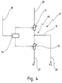
- FIG. 3 shows a first exemplary embodiment of the voltage divider circuit 47 from FIG. 2.
- the voltage divider circuit 47 comprises two voltage dividers 61, 62 connected in parallel, which are connected between the voltage line 28 and the control line 27 to the control input E1.
- a relay 63 is provided which has two changeover contacts 64, 65.
- the changeover contact 64 optionally connects the voltage divider 61 or the voltage divider 62 to the control line 27.
- the changeover contact 65 actuated synchronously with the changeover contact 64, on the other hand, optionally connects the control line 26 to center taps 66 and 67 of the voltage dividers 61 and 62.
- the voltage divider 61 comprises two Resistors R1, R2, by means of their relationship to one another, the control inputs E1 and E2 are connected in such a way that the flashing clock generator 17 expects and monitors two lamps in each direction of travel. If a signal is now present on the trailer detection line 29, this leads to the relay 63 switching the changeover contacts 64, 65, so that the voltage divider 62 now connects the control inputs E1 and E2 with its resistors R1 'and R2'.
- This circuit can be selected, for example, so that the flashing clock generator 17 now expects and monitors three flashing lamps in each direction of travel.
- This voltage divider circuit 47 has a single voltage divider 69, which comprises a series shading of electrically controllable resistors 71, 72.
- Resistors 71, 72 can e.g. Be FETs.
- a schematically indicated control circuit 73 is provided which, depending on signals on the trailer detection line 29, switches the resistors 71, 72 in such a way that they either the resistance values R1 and R2 or the resistance values R1 'and R2' accept.
- This voltage divider 69 is also connected between the voltage line 28 and the control line 27 to the control input E1.
- the center tap 74 is again guided via the control line 26 to the control input E2.
Abstract
Description
Die Erfindung betrifft eine Schaltungsanordnung für eine Blinklichtanlage eines aus einem Zugfahrzeug und einem elektrisch an das Zugfahrzeug anschließbaren Hänger bestehenden Wagenzuges, mit einem Blinktaktgeber, der dazu ausgelegt ist, an seinem Taktausgang sämtliche je Fahrtrichtung vorgesehenen Blinklampen des Zugfahrzeuges zu betreiben, der zumindest einen Steuereingang aufweist, über den die Anzahl der je Fahrtrichtung vorgesehenen und überwachten Blinklampen des Zugfahrzeuges auswählbar ist, und der eine Signallampe zur Anzeige des Blinktaktes treibt, wobei der Blinktaktgeber bei nicht elektrisch angeschlossenem Hänger den Ausfall einer angesteuerten Blinklampe des Zugfahrzeuges über eine erhöhte Blinkfrequenz anzeigt.The invention relates to a circuit arrangement for a turn signal system of a wagon train consisting of a towing vehicle and a trailer which can be electrically connected to the towing vehicle, with a blinking clock generator which is designed to operate at its clock output all the blinking lamps of the towing vehicle which are provided in each direction of travel and which have at least one control input over which the number of the provided in each direction of travel and monitored flashing lamps of the towing vehicle can be selected, and which drives a signal lamp to indicate the flashing cycle, the flashing clock signaling the failure of a controlled flashing lamp of the towing vehicle when the trailer is not electrically connected via an increased flashing frequency.
Derartige Schaltungsanordnungen sind aus der Praxis bekannt.Such circuit arrangements are known from practice.
Die bekannten Schaltungsanordnungen weisen einen Blinktaktgeber auf, der in der Regel je Fahrtrichtung drei Blinklampen treiben kann, und der einen Kontrollausgang aufweist, an dem der je Fahrtrichtung gleichzeitige Betrieb der entsprechenden Blinklampen des Zugfahrzeuges und des Hängers angezeigt wird. Zwei dieser Blinklampen gehören zu der Blinklichtanlage des Zugfahrzeuges und die dritte Blinklampe zu der Blinklichtanlage des Hängers. Sämtliche Blinklampen werden in der Regel parallel betrieben, so daß der Stromfluß aus dem Blinktaktgeber umso größer wird, je mehr Blinklampen angeschlossen sind.The known circuit arrangements have a flashing clock generator, which can generally drive three flashing lamps in each direction of travel, and which has a control output at which the simultaneous operation of the corresponding flashing lamps of the towing vehicle and the trailer is indicated in each direction of travel. Two of these flashing lamps belong to the flashing light system of the towing vehicle and the third flashing lamp to the flashing light system of the trailer. All flashing lights are usually operated in parallel, so that the more flashing lights are connected, the greater the current flow from the flashing clock generator.
Ist der Hänger elektrisch an das Zugfahrzeug angeschlossen, so treibt der Blinktaktgeber folglich drei Blinklampen je Fahrtrichtung. In diesem Falle gibt er an seinem C2 genannten Kontrollausgang ein Signal aus, über das mit dem Blinktakt in der Regel eine Kontrolleuchte betrieben wird, die im Armaturenbrett unterzubringen ist. Anhand dieser im Blinktakt blinkenden Kontrolleuchte kann der Fahrzeugführer erkennen, daß sämtliche drei Blinklampen funktionsfähig sind. Zusätzlich weist die Schaltungsanordnung die übliche Signallampe auf, welche ebenfalls in dem Armaturenbrett vorgesehen ist, und nicht nur den Blinktakt sondern auch die Fahrtrichtungsanzeige wiederspiegelt. Wenn der Blinktaktgeber dagegen nur zwei Blinklampen je Fahrtrichtung treibt, sei es, daß eine der drei Blinklampen je Fahrtrichtung ausgefallen ist, oder daß aber kein Hänger elektrisch angeschlossen ist, so gibt der Blinktaktgeber an seinem Kontrollausgang C2 kein Signal aus. Die Signallampe wird jedoch weiter betrieben und zeigt den Blinktakt und die Fahrtrichtung an.If the trailer is electrically connected to the towing vehicle, the flashing clock generator drives three flashing lamps in each direction of travel. In this case, it outputs a signal at its control output called C2, via which a flashing light is usually operated with the flashing cycle and must be accommodated in the dashboard. On the basis of this indicator light, which flashes in the blinking cycle, the vehicle driver can recognize that all three blinking lamps are functional. In addition, the circuit arrangement has the usual signal lamp, which is also provided in the dashboard, and not only reflects the blinking cycle but also the direction indicator. If, on the other hand, the flashing clock generator drives only two flashing lamps per direction of travel, it is that one of the three flashing lamps per direction of travel has failed, or that no trailer is electrically connected, the flashing clock generator does not output any signal at its control output C2. However, the signal lamp continues to operate and shows the blinking cycle and the direction of travel.
Ist jetzt kein Hänger angeschlossen und fällt zusätzlich eine Blinklampe der Blinklichtanlage des Zugfahrzeuges aus, so erkennt dies der Blinktaktgeber an der veränderten Stromabgabe und schaltet auf eine höhere Blinkfrequenz.If no trailer is now connected and a blinking lamp of the towing vehicle's turn signal system also fails, the blinking clock generator recognizes this from the changed current output and switches to a higher blinking frequency.
Wegen der bei dem bekannten Blinktaktgeber vorgesehenen Steuereingänge ist es ferner möglich, nicht nur die üblicherweise zwei Blinklampen des Zugfahrzeuges je Fahrtrichtung zu treiben und zu überwachen, sondern zusätzlich z.B. auf den Türen oder in den Stoßstangen vorgesehene Blinklampen treiben zu können. Die bekannten Blinktaktgeber sind somit universell einsetzbar, durch eine feste Beschaltung der Steuereingänge mit Spannungsteilern werden die jeweiligen Blinktaktgeber auf die Gegebenheiten des speziellen Zugfahrzeuges abgestimmt. Diese Blinktaktgeber sind dabei dazu ausgelegt, je Fahrtrichtung zwei Blinklampen mit einer Leistungsaufnahme von jeweils 21 W sowie mehrere Blinklampen mit geringerer Leistungsaufnahme zu treiben.Because of the control inputs provided in the known flashing clock generator, it is also possible not only to drive and monitor the usually two flashing lights of the towing vehicle in each direction of travel, but also e.g. to be able to drive flashing lights provided on the doors or in the bumpers. The known flashing clock transmitters can thus be used universally; the respective flashing clock transmitters are matched to the conditions of the special towing vehicle by means of a fixed connection of the control inputs with voltage dividers. These flasher clocks are designed to drive two flasher lamps with a power consumption of 21 W each and several flasher lamps with lower power consumption in each direction of travel.
Bei der insoweit beschriebenen Schaltungsanordnung wird es als Nachteil empfunden, daß der Fahrzeugführer anhand der Betriebszustände der Kontrolleuchte und der Signallampe nicht erkennen kann, ob eine der Blinklampen je Fahrtrichtung ausgefallen ist oder ob der Hänger nicht richtig gesteckt ist.In the circuit arrangement described so far, it is perceived as a disadvantage that the vehicle driver cannot use the operating states of the control lamp and the signal lamp to recognize whether one of the turn signal lamps has failed in each direction of travel or whether the trailer is not correctly inserted.
Hier ist zu bemerken, daß die Blinktaktgeber üblicherweise nur zum Betreiben von zwei Blinklampen (plus ggf. eine z.B. Türblinklampe mit geringerer Leistungsaufnahme) je Fahrtrichtung ausgelegt sind. Soll ein Zugfahrzeug auf Hängerbetrieb umgerüstet werden, so gab es bisher die folgenden beiden Möglichkeiten:It should be noted here that the flasher clock generators are usually only designed to operate two flasher lamps (plus a door flasher lamp, for example, with lower power consumption) in each direction of travel. So far, there are two options for converting a towing vehicle to trailer operation:
Der zum Betreiben von zwei Blinklampen je Fahrtrichtung vorgesehene Blinktaktgeber wird gegen einen solchen ausgetauscht, der drei Blinklampen je Fahrtrichtung betreiben kann, wie dies eingangs bereits beschrieben wurde. Darüberhinaus muß die zusätzliche Kontrolleuchte C2 im Blickfeld des Fahrzeugführers montiert werden. Insbesondere bei Fahrzeugen mit Airbag und ähnlichen Sicherheitseinrichtungen führt insbesondere das nachträgliche Einbauen dieser Kontrolleuchte zu langwierigen und damit kostenintensiven Arbeiten. Insbesondere bei kleinen Zugfahrzeugen ist es darüberhinaus oft gar nicht möglich, diese zusätzliche Kontrolleuchte im Armaturenbrett unterzubringen.The flasher clock generator provided for operating two flasher lamps per direction of travel is replaced by one which can operate three flasher lamps per direction of travel, as was already described at the beginning. In addition, the additional control lamp C2 must be installed in the driver's field of vision. Particularly in vehicles with airbags and similar safety devices, the retrofitting of this indicator light leads to lengthy and therefore cost-intensive work. In addition, especially in the case of small towing vehicles, it is often not possible to accommodate this additional indicator lamp in the dashboard.
Darüberhinaus ist es bekannt, den zum Betreiben von zwei Blinklampen je Fahrtrichtung ausgelegten Blinktaktgeber im Fahrzeug zu belassen und entweder die hintere Blinklampe des Zugfahrzeuges oder die Blinklampe des Hängers über eine hochohmige Treiberschaltung zu betreiben, welche den Blinktaktgeber nicht zusätzlich belastet. Die hierzu erforderliche Schaltungsanordnung umfaßt in der Regel noch eine Fehlererkennungsschaltung, welche die jeweils hochohmig betriebene Blinklampe überwacht. Fällt diese dritte Blinklampe aus, was der Blinktaktgeber nicht erkennen kann, so wird eine der beiden unmittelbar von dem Blinktaktgeber betriebenen Blinklampen von dem Blinktaktgeber weggeschaltet und ebenfalls hochohmig betrieben. Auf diese Weise wird dem Blinktaktgeber der Ausfall einer Blinklampe simuliert, was dazu führt, daß der Blinktaktgeber auf die erhöhte Blinkfrequenz umschaltet.In addition, it is known to leave the flashing clock generator designed to operate two flashing lamps in each direction of travel in the vehicle and to operate either the rear flashing lamp of the towing vehicle or the flashing lamp of the trailer via a high-impedance driver circuit which does not additionally burden the flashing clock generator. The circuit arrangement required for this usually also includes an error detection circuit which monitors the flashing lamp operated in a high-resistance manner. If this third flashing lamp fails, which the flashing clock generator cannot recognize, then one of the two flashing lamps operated directly by the flashing clock generator is switched off by the flashing clock generator and also operated with high resistance. In this way, the failure of a flashing lamp is simulated for the flashing clock generator, which leads to the flashing clock generator switching over to the increased flashing frequency.
Bei dieser z.B. aus der DE-OS 41 34 993 bekannten Schaltung ist es von Nachteil, daß eine große Anzahl von Bauteilen benötigt wird, um einerseits für das hochohmige Abgreifen und andererseits für das Wegschalten zur Fehlersimulation zu sorgen. Zwar sind mit dieser Schaltungsanordnung die Einbauprobleme beseitigt, welche mit dem Nachrüsten eines für drei Blinklampen vorgesehenen Blinktaktgebers sowie der zugehörigen Kontrolleuchte verbunden sind, es bleiben jedoch die hohen Kosten.With this e.g. from DE-OS 41 34 993 known circuit, it is disadvantageous that a large number of components are required, on the one hand to ensure high-resistance tapping and on the other hand to disconnect for fault simulation. Although this circuit arrangement eliminates the installation problems associated with retrofitting a flashing clock generator provided for three flashing lamps and the associated control lamp, the high costs remain.
Darüberhinaus ist es aus der DE-OS 41 35 546 bekannt, in die Blinklichtanlage des Zugfahrzeuges zur Beeinflussung des Blinktaktgebers einen Fehlerstrom einzuspeisen, wenn die hochohmig betriebene Blinklampe des Hängers defekt ist. Bei dieser Anordnung kann auf das Wegschalten einer intakten Blinklampe zwar verzichtet werden, es sind jedoch immer noch eine Reihe von Bauteilen erforderlich, welche zu erhöhten Kosten führen. So ist es z.B. nötig, neben der Fehlererkennungsschaltung noch eine Hängererkennungsschaltung vorzusehen, welche anhand eines gesonderten Massekontaktes oder anhand der über weitere Lampen der Signalanlage des Hängers gelieferten Massekontakte erkennt, ob tatsächlich ein Hänger elektrisch an das Zugfahrzeug angeschlossen ist.Furthermore, it is known from DE-OS 41 35 546 to feed a fault current into the flashing light system of the towing vehicle to influence the flashing clock generator if the high-resistance flashing lamp of the trailer is defective. With this arrangement, there is no need to switch off an intact flashing lamp, but a number of components are still required, which lead to increased costs. So it is e.g. In addition to the error detection circuit, it is necessary to provide a trailer detection circuit which detects whether a trailer is actually electrically connected to the towing vehicle by means of a separate ground contact or by means of the ground contacts supplied via further lamps of the trailer signal system.
Darüberhinaus müssen die bekannten Schaltungen in sogenannten Anhängermodulen im Bereich des Übergabesteckers zwischen Zugfahrzeug und Anhänger im Heck des Zugfahrzeuges untergebracht werden. Dies ist aus Platzgründen jedoch oft mit großem Aufwand verbunden.In addition, the known circuits must be housed in so-called trailer modules in the area of the transfer plug between the towing vehicle and the trailer in the rear of the towing vehicle. However, this is often associated with great effort for reasons of space.
Ausgehend von diesem Stand der Technik ist es Aufgabe der vorliegenden Erfindung, eine Schaltungsanordnung der eingangs genannten Art dahingehend weiterzubilden, daß es bei geringem Bauteil- und Montageaufwand möglich wird, sowohl die Blinklampen des Zugfahrzeuges als auch die nur ggf. angeschalteten Blinklampen des Hängers zu überwachen.Based on this prior art, it is an object of the present invention to further develop a circuit arrangement of the type mentioned in such a way that it is possible to monitor both the flashing lights of the towing vehicle and the possibly only switched on flashing lights of the trailer with little outlay on components and assembly .
Erfindungsgemäß wird diese Aufgabe dadurch gelöst, daß der oder jeder Steuereingang des Blinktaktgebers mit Schaltmitteln verbunden ist, die bei elektrisch angeschlossenem Hänger den oder jeden Steuereingang derart beschalten, daß der Blinktaktgeber bei Ausfall einer angesteuerten Blinklampe auf die erhöhte Blinkfrequenz schaltet.According to the invention this object is achieved in that the or each control input of the flashing clock is connected to switching means which, when the trailer is electrically connected, connects the or each control input in such a way that the flashing clock switches to the increased flashing frequency in the event of a controlled flashing lamp failure.
Die der Erfindung zugrundeliegende Aufgabe wird auf diese Weise vollkommen gelöst. Die erfindungsgemäß vorgesehenen Schaltmittel beeinflussen den Blinktaktgeber jetzt nämlich über die Steuereingänge, welche eigentlich nur für eine feste Beschaltung während der Montage in dem Zugfahrzeug vorgesehen sind. Der Anmelder hat jedoch überraschenderweise gefunden, daß durch eine entsprechende noch näher zu erläuternde Beeinflussung des Blinktaktgebers über die Steuereingänge eine einfache Fehleranzeige möglich ist.The object underlying the invention is completely achieved in this way. The switching means provided according to the invention now influence the flashing clock generator via the control inputs, which are actually only intended for fixed wiring during assembly in the towing vehicle. However, the applicant has surprisingly found that by influencing the flashing clock generator via the control inputs, which is yet to be explained in more detail, a simple error display is possible.
Die Schaltmittel können z.B. die oben erwähnten Fehlererkennungsschaltungen umfassen, so daß sie zunächst den Ausfall einer angesteuerten Blinklampe erkennen. Wenn der Blinktaktgeber zum Betreiben von zwei Blinklampen im Zugfahrzeug sowie zusätzlich einer Blinklampe im Hänger je Fahrtrichtung ausgerüstet ist, so würde dieser Ausfall einer Blinklampe zunächst nicht dazu führen, daß der Blinktaktgeber auf die erhöhte Blinkfrequenz umschaltet. Dieser Ausfall würde vielmehr lediglich auf dem ggf. vorhandenen Kontrollausgang angezeigt. Über die Schaltmittel werden die Steuereingänge jetzt jedoch in der Weise beschaltet, daß der Blinktaktgeber nun zum Betreiben von drei Blinklampen im Zugfahrzeug sowie einer zusätzlichen Blinklampe im Hänger je Fahrtrichtung geschaltet ist. Da jedoch in Wirklichkeit nur insgesamt drei Blinklampen je Fahrtrichtung vorgesehen sind, erkennt der Blinktaktgeber einen Fehler und schaltet auf die erhöhte Blinkfrequenz. Hier ist von ganz besonderem Vorteil, daß auf den Einbau der C2-Kontrolleuchte im Armaturenbrett verzichtet werden kann. Die sowieso vorhandene Signallampe zur Anzeige des Blinktaktes wird durch diese "Umsteuerung" des Blinktaktgebers zur Fehleranzeige verwendet.The switching means can include, for example, the error detection circuits mentioned above, so that they first recognize the failure of a controlled flashing lamp. If the flasher clock generator is equipped to operate two flasher lamps in the towing vehicle and an additional flasher lamp in the trailer for each direction of travel, this failure of a flasher lamp would initially not result in the flasher clock generator switching to the increased flashing frequency. Rather, this failure would only occur on the any existing control output is displayed. However, the control inputs are now connected via the switching means in such a way that the flashing clock generator is now switched to operate three flashing lamps in the towing vehicle and an additional flashing lamp in the trailer for each direction of travel. However, since in reality only three flashing lights are provided in each direction of travel, the flashing clock sensor detects an error and switches to the increased flashing frequency. It is of particular advantage here that the C2 indicator light can be dispensed with in the dashboard. The signal lamp for displaying the flashing clock which is present anyway is used by this "reversal" of the flashing clock for error display.
Eine derartige Beschaltung ist möglich, weil nach den Erkenntnissen des Anmelders durch eine geeignete Beschaltung der Steuereingänge die entsprechende Schaltschwelle im Blinktaktgeber so hoch gelegt werden kann, daß dieser auch drei Blinklampen mit 21 W Leistung überwachen kann.Such a connection is possible because, according to the applicant's knowledge, the appropriate switching threshold in the flashing clock generator can be set so high by suitable wiring of the control inputs that it can also monitor three flashing lamps with a power of 21 W.
Zusammengefaßt ist bei der neuen Schaltungsanordnung also von Vorteil, daß auf den Einbau der C2-Kontrolleuchte im Armaturenbrett während des Umrüstens eines Zugfahrzeuges auf Hängerbetrieb verzichtet werden kann. Es ist lediglich ein neuer Blinkgeber einzubauen, welcher über die neue Schaltungsanordnung in der soeben beschriebenen Weise betrieben wird. Gegenüber den eingangs genannten Maßnahmen der Fehlerstromeinspeisung oder des Wegschaltens bzw. Zuschaltens von hochohmig betriebenen Blinklampen hat die neue Schaltungsanordnung den weiteren Vorteil, daß erheblich weniger Bauteile erforderlich sind. So kann z.B. vollständig auf die erforderlichen Relais verzichtet werden. Die neue Schaltungsanordnung kann darüber hinaus mit den gleichen Vorteilen auch in Neufahrzeugen bei der Produktion eingebaut werden.In summary, it is advantageous in the new circuit arrangement that the C2 control lamp can be dispensed with in the dashboard while converting a towing vehicle to trailer operation. It is only necessary to install a new flasher unit, which is operated via the new circuit arrangement in the manner just described. Compared to the measures mentioned at the beginning of the leakage current feed or the disconnection or connection of high-resistance flashing lamps, the new circuit arrangement has the further advantage that considerably fewer components are required. For example, the required relays can be completely dispensed with. The new circuit arrangement can also be installed in the production of new vehicles with the same advantages.
In einer Weiterbildung ist es bevorzugt, wenn die Schaltmittel bei elektrisch angeschlossenem Hänger den oder jeden Steuereingang derart beschalten, daß die Anzahl der überwachten Blinklampen gleich der Anzahl der Blinklampen je Fahrtrichtung ist.In a further development, it is preferred if the switching means, when the trailer is electrically connected, connect the or each control input in such a way that the number of monitored flashing lamps is equal to the number of flashing lamps per direction of travel.
Bei dieser Maßnahme ist von Vorteil, daß die Schaltmittel selbst keine Fehlererkennungsschaltungen mehr umfassen müssen, so daß sie konstruktiv noch einfacher aufgebaut werden können, als es aus dem Stand der Technik bekannt ist. In dem Augenblick, in dem ein Hänger elektrisch angeschlossen wird, wird dies über geeignete Maßnahmen den Schaltmitteln mitgeteilt, welche über die Steuereingänge den Blinktaktgeber dann so beschalten, als ob eine größere Anzahl von Blinklampen im Zugfahrzeug selbst vorhanden sei. Die Fähigkeit des Blinktaktgebers, den Ausfall einer Lampe des Zugfahrzeuges zu erkennen, wird somit quasi doppelt ausgenutzt. Derartige Maßnahmen sind aus dem Stand der Technik nicht bekannt, denn bisher wurde ja die C2-Kontrolleuchte zusätzlich verwendet, um - wie oben ausführlich beschrieben - eine zusätzliche Information über die Blinklampen des Hängers zu geben.This measure has the advantage that the switching means themselves no longer have to comprise error detection circuits, so that they can be constructed in a structurally simpler manner than is known from the prior art. At the moment when a trailer is electrically connected, this is communicated to the switching means by means of suitable measures, which then connect the flashing clock generator via the control inputs as if a larger number of flashing lamps were present in the towing vehicle itself. The flashing clock's ability to detect the failure of a lamp in the towing vehicle is thus used in two ways. Such measures are not known from the prior art, because up to now the C2 indicator light has been used in addition to provide additional information about the trailer's flashing lights, as described in detail above.
Die neue Schaltungsanordnung ist damit extrem einfach aufzubauen, denn sie benötigt lediglich einen Eingang, auf dem ihr der elektrische Anschluß eines Hängers "mitgeteilt" wird. In Abhängigkeit von dieser Information beschalten die Schaltmittel die Steuereingänge des Blinktaktgebers so, daß er sämtliche Blinklampen des Wagenzuges überwacht. Auch der Einbau der neuen Schaltungsanordnung gestaltet sich wesentlich einfacher als es aus dem eingangs diskutierten Stand der Technik bekannt ist. Soll nämlich ein Zugfahrzeug auf Hängerbetrieb umgerüstet werden, so muß nunmehr lediglich der Blinkgeber gewechselt und die neue Schaltungsanordnung eingebaut werden. Der Blinkgeber und die externe Beschaltung durch die neue Schaltungsanordnung können jedoch auch monolithisch als ein einziges IC oder aber als gedruckte Leiterplatte ausgelegt sein, so daß lediglich der bisherige Blinkgeber durch dieses neue Bauteil ersetzt werden muß. Darüberhinaus ist es lediglich erforderlich, für die Hängererkennung zu sorgen, was beispielsweise durch einen von dem Fahrzeugführer zu betätigenden Schalter erfolgen kann.The new circuit arrangement is thus extremely simple to set up, since it only requires an input on which the electrical connection of a trailer is "communicated" to it. Depending on this information, the switching means connect the control inputs of the flashing clock so that it monitors all the flashing lights of the wagon train. The installation of the new circuit arrangement is also much easier than is known from the prior art discussed at the outset. If a towing vehicle is to be converted to trailer operation, all that now has to be changed is the flasher unit and the new one Circuit arrangement can be installed. The flasher unit and the external circuitry through the new circuit arrangement can also be designed monolithically as a single IC or as a printed circuit board, so that only the previous flasher unit has to be replaced by this new component. In addition, it is only necessary to provide trailer detection, which can be done, for example, by a switch to be actuated by the vehicle driver.
Hier ist es ferner bevorzugt, wenn eine Hängererkennungsschaltung vorgesehen ist, die einen elektrisch an das Zugfahrzeug angeschlossenen Hänger auf einer Hängererkennungsleitung meldet.It is further preferred here if a trailer detection circuit is provided which reports a trailer electrically connected to the towing vehicle on a trailer detection line.
Hier ist von Vorteil, daß der Hänger automatisch erkannt wird, so daß der Fahrzeugführer nicht mehr nach dem Ankoppeln und elektrischen Anschalten des Hängers einen entsprechenden Schalter umlegen muß. Dies führt insoweit ebenfalls zu einer Reduzierung der Bauteile, da der zusätzliche Schalter wegfällt. Die Hängererkennungsschaltung ist an sich aus dem Stand der Technik bekannt. Neben der Abfrage der Hängermasse kann sie ihre Informationen auch durch Überwachung des Stromflusses beispielsweise durch den Schalter für Bremslicht und/oder Standlicht ableiten. Ein erhöhter Stromfluß deutet auf einen angeschlossenen Hänger hin.The advantage here is that the trailer is recognized automatically, so that the vehicle driver no longer has to flip an appropriate switch after coupling and electrically switching on the trailer. This also leads to a reduction in the number of components, since the additional switch is omitted. The trailer detection circuit is known per se from the prior art. In addition to querying the trailer mass, it can also derive its information by monitoring the current flow, for example using the switch for the brake light and / or parking light. An increased current flow indicates a connected trailer.
Dabei ist es weiter bevorzugt, wenn bei einem Blinktaktgeber mit Kontrollausgang C2 die Hängererkennungsschaltung mit dem Kontrollausgang des Blinktaktgebers verbunden ist und aus den Signalen des Kontrollausganges einen elektrisch angeschlossenen Hänger erkennt.It is further preferred if, in the case of a flashing clock generator with control output C2, the trailer detection circuit is connected to the control output of the flashing clock generator and recognizes an electrically connected trailer from the signals of the control output.
Hier ist jetzt weiter von Vorteil, daß das sowieso erzeugte Signal auf dem Kontrollausgang dazu verwendet wird, einen Hänger zu erkennen. Dabei wird ausgenutzt, daß der Kontrollausgang nur dann ein Signal abgibt, wenn auch tatsächlich ein Hänger elektrisch angeschlossen ist und die Blinklichtanlage des Wagenzuges entsprechend betätigt wird. Die aus dem Stand der Technik bekannten Maßnahmen, einen zusätzlichen Hängererkennungskontakt oder eine Masseabfragevorrichtung für die Hängermasse vorzusehen, können damit entfallen. Auch dies führt zu einem sehr geringen Bauteilbedarf. Ferner ist es jetzt möglich, nicht nur die neuen Schaltmittel vorne im Zugfahrzeug unterzubringen, sondern auch die Hängererkennung ohne zusätzliche Leitungen zum Heck des Zugfahrzeuges aus vorne vorhandenen Informationen abzuleiten.Another advantage here is that the signal generated anyway on the control output is used to detect a trailer. This takes advantage of the fact that the control output only emits a signal when a trailer is actually electrically connected and the flashing light system of the wagon train is actuated accordingly. The measures known from the prior art of providing an additional trailer detection contact or a mass interrogation device for the trailer mass can thus be omitted. This also leads to a very low component requirement. Furthermore, it is now possible not only to accommodate the new switching means in the front of the towing vehicle, but also to derive the trailer detection without additional lines to the rear of the towing vehicle from information available at the front.
Bei dieser Ausführung ist es bevorzugt, wenn die Hängererkennungsschaltung ein Speicherelement umfaßt, welches das erste Ansprechen des Kontrollausgangs speichert und permanent auf der Hängererkennungsleitung meldet.In this embodiment, it is preferred if the trailer detection circuit comprises a memory element which stores the first response of the control output and permanently reports on the trailer detection line.
Diese Maßnahme ist insbesondere unter schaltungstechnischen Randbedingungen von Vorteil, denn es muß lediglich ein Speicherelement vorgesehen sein, was nach dem ersten Ansprechen des Kontrollausganges in einen permanenten Zustand geschaltet wird, aus dem es beispielsweise erst nach dem Öffnen des Zündschalters wieder zurückgesetzt wird. Mit anderen Worten geht das Speicherelement beispielsweise nach dem Starten des Zugfahrzeuges zunächst in einen Grundzustand, in dem es kein Signal auf der Hängererkennungsleitung ausgibt. Wird dann zum ersten Mal der Fabrtrichtungsschalter betätigt, so spricht der Kontrollausgang an, was von dem Speicherelement gespeichert wird. Auf diese Weise kann im einfachsten Fall ein Flip-Flop an den Kontrollausgang angeschlossen werden, wobei der Ausgang des Flip-Flops dann mit der Hängererkennungsleitung verbunden wird.This measure is particularly advantageous under technical circuit conditions, because only one memory element must be provided, which is switched to a permanent state after the first response of the control output, from which it is only reset, for example, after the ignition switch has been opened. In other words, after the towing vehicle has started, the storage element initially goes into a basic state in which it does not output a signal on the trailer detection line. If the factory direction switch is then actuated for the first time, the control output responds to what is stored by the storage element. In the simplest case, a flip-flop can be connected to the control output in this way, the output of the flip-flop then being connected to the trailer detection line.
Insgesamt ist es hierbei bevorzugt, wenn der Kontrollausgang mit einer akustischen Einrichtung verbunden ist.Overall, it is preferred if the control output is connected to an acoustic device.
Es wurde bereits erwähnt, daß bei der neuen Schaltungsanordnung auf das Nachrüsten der zusätzlichen Kontrolleuchte im Armaturenbrett verzichtet werden kann. Um jedoch in Übereinstimmung mit dem § 54 STVO für eine Anzeige des Hängerbetriebes zu sorgen, wird die akustische Einrichtung vorgesehen. Der Kontrollausgang kann nun entweder jedesmal bei seinem Ansprechen über die akustische Einrichtung ein akustisches Signal abgeben, so daß der Fahrzeugführer jederzeit über die Funktionsfähigkeit sämtlicher Blinklampen je Fahrtrichtung informiert ist, oder dies aber nur einmal zu Beginn der Fahrt tun. Da der Fahrzeugführer weiß, daß er über die übliche Signallampe vollständig über den Zustand seiner Blinklichtanlage informiert wird, kann das zusätzliche akustische Signal nun dazu verwendet werden, dem Fahrzeugführer zu Beginn der Fahrt einmal anzuzeigen, daß der Hänger korrekt elektrisch an das Zugfahrzeug angeschlossen wurde. Fehlt das Signal, so muß der Fahrzeugführer gleich zu Fahrtbeginn die Blinklichtanlage überprüfen.It has already been mentioned that the additional control lamp in the dashboard can be dispensed with in the new circuit arrangement. However, in order to provide an indication of trailer operation in accordance with § 54 STVO, the acoustic device is provided. The control output can now either give an acoustic signal each time it responds via the acoustic device, so that the vehicle driver is informed at all times about the functionality of all flashing lights in each direction of travel, or do so only once at the start of the journey. Since the driver knows that he is fully informed about the status of his flashing light system via the usual signal lamp, the additional acoustic signal can now be used to indicate to the driver at the start of the trip that the trailer has been correctly electrically connected to the towing vehicle. If the signal is missing, the driver must check the turn signal system right at the start of the journey.
Beim Austausch des für zwei Blinklampen je Fahrtrichtung vorgesehenen Blinktaktgebers gegen den für drei Blinklampen vorgesehenen Blinktaktgebers kann die neue Schaltanordnung mit eingebaut werden, ohne daß größere Montagearbeiten an dem Zugfahrzeug durchgeführt werden müssen. Die neue Schaltungsanordnung umfaßt derart wenige Bauteile, daß sie sehr preiswert hergestellt werden kann. Darüberhinaus ist der Montageaufwand verglichen mit dem Einbau der zusätzlichen Kontrolleuchte vernachlässigbar gering.When replacing the flashing clock provided for two flashing lamps in each direction of travel with the flashing clock provided for three flashing lights, the new switching arrangement can be installed without having to carry out major assembly work on the towing vehicle. The new circuit arrangement comprises so few components that it can be manufactured very inexpensively. In addition, the assembly effort is negligible compared to the installation of the additional control lamp.
Ferner ist es bevorzugt, wenn die Hängererkennungsschaltung mit einer Reset-Vorrichtung verbunden ist, über welche die Hängererkennungsleitung zurückschaltbar ist.It is further preferred if the trailer detection circuit is connected to a reset device, via which the trailer detection line can be switched back.
Diese Maßnahme ist insbesondere dann von Vorteil, wenn der Fahrzeugführer bei laufendem Zugfahrzeug den Hänger abkoppelt. Wäre jetzt keine Reset-Vorrichtung vorgesehen, so würde die Hängererkennungsschaltung immer noch den vorher gespeicherten Zustand eines angeschalteten Hängers auf der Hängererkennungsleitung ausgeben. Dies würde beim Betätigen des Fahrtrichtungsschalters dazu führen, daß die Schaltmittel einen Fehlerzustand erkennen und den Blinktaktgeber entsprechend beeinflussen.This measure is particularly advantageous if the driver decouples the trailer while the towing vehicle is running. If no reset device were now provided, the trailer detection circuit would still output the previously stored state of a connected trailer on the trailer detection line. When the travel direction switch was actuated, this would result in the switching means recognizing an error state and influencing the flashing clock generator accordingly.
Dabei ist es bevorzugt, wenn die Reset-Vorrichtung einen Schließkontakt umfaßt.It is preferred if the reset device comprises a make contact.
Dies ist die schaltungstechnisch einfachste Möglichkeit, einen Speicherbaustein zurückzusetzen. Dieser Schließkontakt kann ein Druckschalter sein, den der Fahrzeugführer nach dem Abkoppeln des Hängers kurz betätigt, um die Hängererkennungsschaltung zurückzusetzen. Gegenüber dem Einbau der im Blickfeld des Fahrers anzubringenden C2-Lampe hat dies den Vorteil, daß der Druckschalter an einer beliebigen Stelle untergebracht werden kann, was zu erheblich erleichterten Einbaubedingungen führt. Der Schließkontakt kann aber auch ein Türkontakt sein, der beim Öffnen der Fahrertür oder der Beifahrertür geschlossen wird. Steigen jetzt der Fahrer oder der Beifahrer aus dem laufenden Zugfahrzeug aus, um einen Hänger abzukoppeln, so führt dies automatisch zum Zurücksetzen der Hängererkennungsschaltung.In terms of circuitry, this is the simplest way to reset a memory chip. This make contact can be a pressure switch, which the driver briefly actuates after uncoupling the trailer in order to reset the trailer detection circuit. Compared to the installation of the C2 lamp to be installed in the driver's field of vision, this has the advantage that the pressure switch can be accommodated at any point, which leads to considerably easier installation conditions. The make contact can also be a door contact that is closed when the driver's door or the passenger's door is opened. If the driver or front passenger get out of the running towing vehicle to uncouple a trailer, this automatically leads to the trailer detection circuit being reset.
Dabei ist es weiter bevorzugt, wenn die Reset-Vorrichtung eine Meßvorrichtung für den Stromfluß durch ausgewählte Lampen des Hängers umfaßt und in Abhängigkeit von dem Stromfluß die Hängererkennungsleitung zurückschaltet.It is further preferred if the reset device comprises a measuring device for the current flow through selected lamps of the trailer and switches the trailer detection line back on as a function of the current flow.
Hier ist von Vorteil, daß auch dann, wenn eine dritte Person den Hänger abkoppelt, ohne daß eine der Türen geöffnet wurde, die Hängererkennungsschaltung jetzt durch die Meßvorrichtung zurückgesetzt wird. Zu diesen ausgewählten Lampen zählen vorzugsweise das Bremslicht oder das Standlicht. Die Reset-Vorrichtung muß lediglich über zwei Kabel mit dem entsprechenden Schalter beispielsweise für das Bremslicht verbunden werden, wobei die Meßvorrichtung zwischen Zuständen unterscheiden kann, in denen nur die Zugfahrzeug- oder zusätzlich noch die Hängerlampen angesteuert werden. Nachdem der Hänger abgekoppelt wurde, wird somit beim ersten Bremsen erkannt, daß kein Hänger vorliegt. Die Reset-Vorrichtung gibt daraufhin ein Rücksetzsignal an die Hängererkennungsschaltung aus.The advantage here is that even if a third person decouples the trailer without opening one of the doors, the trailer detection circuit is now reset by the measuring device. These selected lamps preferably include the brake light or the parking light. The reset device only has to be connected to the corresponding switch, for example for the brake light, by means of two cables, the measuring device being able to differentiate between states in which only the towing vehicle lamps or additionally the trailer lamps are controlled. After the trailer has been uncoupled, it is recognized when the first braking that there is no trailer. The reset device then outputs a reset signal to the trailer detection circuit.
Insgesamt ist es bevorzugt, wenn der Kontrollausgang mit einer Verriegelungsschaltung verbunden ist, die in Abhängigkeit von dem Betrieb der Warnblinkanlage den Kontrollausgang von der Hängererkennungsschaltung abkoppelt.Overall, it is preferred if the control output is connected to a locking circuit which, depending on the operation of the hazard warning system, decouples the control output from the trailer detection circuit.
Diese Maßnahme ist für Blinktaktgeber vorgesehen, die auch dann ein C2-Signal ausgeben, wenn ohne elektrisch angeschlossenen Hänger die Warnblinkanlage betätigt wird, wenn also insgesamt vier Lampen von dem Blinktaktgeber versorgt werden. Diese Blinktaktgeber können nicht zwischen dem Betrieb von drei Blinklampen - Zugfahrzeug + Hänger - und dem Betrieb von vier Blinklampen - kein Hänger, aber Warnblinkanlage des Zugfahrzeuges eingeschaltet - unterscheiden. Daher muß die beim Betrieb der Warnblinkanlage fehlerhaft erfolgende Hängererkennung verhindert oder rückgängig gemacht werden. Zu diesem Zweck ist die Verriegelungsschaltung vorgesehen, die den Kontrollausgang von der Hängererkennungsschaltung abkoppelt. Auf diese Weise ist sichergestellt, daß beim Betrieb der Warnblinkanlage der Kontrollausgang der Hängererkennungsschaltung nicht in den Zustand schaltet, in dem sie auf ihrer Hängererkennungsleitung einen elektrisch angeschlossenen Hänger meldet.This measure is intended for flashing clock transmitters, which also output a C2 signal when the hazard warning system is operated without an electrically connected trailer, that is, when a total of four lamps are supplied by the flashing clock generator. These flasher clock generators cannot distinguish between the operation of three flasher lamps - towing vehicle + trailer - and the operation of four flasher lamps - no trailer, but hazard warning system of the towing vehicle switched on. Therefore, the operation of the Hazard warning system incorrectly occurring trailer detection can be prevented or reversed. For this purpose, the locking circuit is provided, which decouples the control output from the trailer detection circuit. In this way it is ensured that, when the hazard warning system is in operation, the control output of the trailer detection circuit does not switch to the state in which it reports an electrically connected trailer on its trailer detection line.
Weiter ist es bevorzugt, wenn die Verriegelungsvorrichtung eine Meßschaltung für den von dem Blinktaktgeber abgegebenen Lampenstrom aufweist.It is further preferred if the locking device has a measuring circuit for the lamp current emitted by the flashing clock generator.
Hier ist von Vorteil, daß die Verriegelungsschaltung selbst erkennt, ob der Blinktaktgeber drei oder vier Lampen betreibt. Nur in dem Fall, in dem vier Lampen betrieben werden, wird der Kontrollausgang von der Hängererkennungsschaltung abgekoppelt. Hier ergeben sich aber auch keine Probleme, wenn beim Betrieb der Warnblinkanlage nur drei Lampen in Betrieb sind, weil eine der Lampen der Blinklichtanlage des Zugfahrzeuges ausgefallen ist. Zwar wird durch das Betätigen der Warnblinkanlage die Hängererkennungsschaltung entsprechend gesetzt, die daraufhin bei normalem Betrieb der Blinklichtanlage erfolgende Fehlermeldung würde jedoch sowieso zumindest in einer Fahrtrichtung erfolgen. Das gespeicherte Hängererkennungssignal veranlaßt die Schaltmittel nun nämlich, den Blinktaktgeber so zu beschalten, als ob ein Hänger angeschaltet wäre. Mit anderen Worten erwartet der Blinktaktgeber jetzt z.B. drei mal 21 W Leistungsaufnahme je Fahrtrichtung, also zwei mal 21 W vom Zugfahrzeug und ein mal 21 W vom Hänger. Da aber tatsächlich eine der Lampen des Zugfahrzeuges defekt ist, bietet diese Maßnahme sogar den zusätzlichen Vorteil, daß die defekte Lampe auch dann angezeigt wird, wenn der Fahrtrichtungsschalter bei dem augenblicklichen Schaltungszustand zwei funktionierende Lampen ansteuert, obwohl eine der Lampen der zur Zeit nicht ausgewählten Fahrtrichtung defekt ist.The advantage here is that the locking circuit itself detects whether the flashing clock operates three or four lamps. The control output is only decoupled from the trailer detection circuit if four lamps are operated. However, there are no problems here if only three lamps are in operation when the hazard warning system is in operation, because one of the lamps in the flashing system of the towing vehicle has failed. Actuating the hazard warning lights sets the trailer detection circuit accordingly, but the error message that would then occur during normal operation of the flashing lights system would occur anyway in at least one direction of travel. The stored trailer detection signal now causes the switching means to connect the flashing clock generator as if a trailer were switched on. In other words, the flashing clock generator now expects, for example, three times 21 W power consumption in each direction, ie two times 21 W from the towing vehicle and one time 21 W from the trailer. However, since one of the lamps of the towing vehicle is actually defective, this measure even has the additional advantage that the defective lamp is then also displayed becomes when the direction switch switches two functioning lamps in the current switching state, although one of the lamps of the direction not currently selected is defective.
Hier ist es bevorzugt, wenn die Schaltmittel eine Spannungsteilerschaltung umfassen, welche in Abhängigkeit von Signalen auf der Hängererkennungsleitung verschiedene Spannungsteiler mit den Steuereingängen verbindet.It is preferred here if the switching means comprise a voltage divider circuit which, depending on signals on the trailer detection line, connects different voltage dividers to the control inputs.
Auch diese Maßnahme ist schaltungstechnisch von Vorteil, denn die Beschaltung der Steuereingänge mit unterschiedlichen Spannungsteilern ist die einfachste Möglichkeit, den Blinktaktgeber in der gewünschten Weise zu beeinflussen. Es können z.B. zwei verschiedene Spannungsteiler einmal für den Betriebszustand mit zwei überwachten Blinklampen je Fahrtrichtung und einmal für den Betriebszustand mit drei überwachten Blinklampen je Fahrtrichtung (angeschalteter Hänger) vorgesehen sein, zwischen denen mittels eines Relais oder elektronischen Umschalters in Abhängigkeit von der Hängererkennung umgeschaltet wird.This measure is also advantageous in terms of circuitry, because wiring the control inputs with different voltage dividers is the simplest way to influence the flashing clock generator in the desired manner. For example, Two different voltage dividers are provided, one for the operating state with two monitored flashing lamps per direction of travel and one for the operating state with three monitored flashing lamps per direction of travel (trailer switched on), between which switching takes place by means of a relay or electronic switch depending on the trailer detection.
Dabei ist es bevorzugt, wenn nur ein Spannungsteiler vorgesehen ist, der elektronisch steuerbare Widerstände umfaßt, wobei das Spannungsteilerverhältnis in Abhängigkeit von Signalen auf der Hängererkennungsleitung veränderbar ist.It is preferred if only one voltage divider is provided, which includes electronically controllable resistors, the voltage divider ratio being variable as a function of signals on the trailer detection line.
Hier ist von Vorteil, daß der Bauteilbedarf noch weiter reduziert wird. Insbesondere ist kein Relais oder ähnlicher mechanischer Umschalter mehr erforderlich, es können vielmehr elektronisch steuerbare Widerstände in Form z.B. von FETs gewählt werden, die sich einfach in einer integrierten Schaltung realisieren lassen.The advantage here is that the component requirement is reduced even further. In particular, a relay or similar mechanical changeover switch is no longer required; rather, electronically controllable resistors in the form of FETs, for example, can be selected, which can be easily implemented in an integrated circuit.
Weitere Vorteile ergeben sich aus der Beschreibung und der beigefügten Zeichnung.Further advantages result from the description and the attached drawing.
Es versteht sich, daß die vorstehend genannten und die nachstehend noch zu erläuternden Merkmale nicht nur in der jeweils angegebenen Kombination, sondern auch in anderen Kombinationen und in Alleinstellung verwendbar sind, ohne den Rahmen der vorstehenden Erfindung zu verlassen.It goes without saying that the features mentioned above and those yet to be explained below can be used not only in the combination specified in each case, but also in other combinations and on their own without departing from the scope of the above invention.
Die Erfindung ist in der Zeichnung dargestellt und wird in der nachfolgenden Beschreibung näher erläutert. Es zeigen:
- Fig. 1
- eine prinzipielle Darstellung der neuen Schaltungsanordnung, in welcher die Blinklampen einer Fahrtrichtung, der Blinktaktgeber und die Schaltmittel schematisch dargestellt sind;
- Fig. 2
- ein Ausführungsbeispiel der Schaltmittel aus Fig. 1 mit schematisch angedeuteter Spannungsteilerschaltung;
- Fig. 3
- ein Ausführungsbeispiel der Spannungsteilerschaltung aus Fig. 2; und
- Fig. 4
- ein zweites Ausführungsbeispiel der Spannungsteilerschaltung aus Fig. 2.
- Fig. 1
- a schematic representation of the new circuit arrangement in which the flashing lights of a direction of travel, the flashing clock generator and the switching means are shown schematically;
- Fig. 2
- an embodiment of the switching means of Figure 1 with a schematically indicated voltage divider circuit.
- Fig. 3
- an embodiment of the voltage divider circuit of Fig. 2; and
- Fig. 4
- 2 shows a second exemplary embodiment of the voltage divider circuit from FIG. 2.
In Fig. 1 ist insgesamt mit 10 eine Schaltungsanordnung für eine bei 11 angedeutete Blinklichtanlage eines Wagenzuges bezeichnet. Die Blinklichtanlage 11 umfaßt je Fahrtrichtung drei Blinklampen 12, 13, 14. Die Blinklampen 12 und 13 sind Blinklampen des Zugfahrzeuges, während die Blinklampe 14 zu einem an das nicht dargestellte Zugfahrzeug elektrisch angeschlossenen Hänger gehört und über einen bei 15 gezeigten Stecker zu den Blinklampen 12 und 13 parallel geschaltet ist.A circuit arrangement for a flashing light system, indicated at 11, of a wagon train is designated in FIG. 1 overall. The
Die Blinklichtanlage 11 ist in Fig. 1 nur für eine Fahrtrichtung dargestellt, die Blinklampen der zweiten Fahrtrichtung sind jedoch entsprechend verschaltet.The
Zum Betreiben der Blinklichtanlage 11 ist ein Blinktaktgeber 17 vorgesehen, welcher über einen mit ZS bezeichneten Zündschalter 18 mit einer Versorgungsspannung 19 verbunden ist, die üblicherweise dem Plusanschluß der Fahrzeugbatterie entspricht. Die äußere Beschaltung ist nur insoweit gezeigt, als sie für das Verständnis der neuen Schaltungsanordnung erforderlich ist.To operate the flashing
Der Blinktaktgeber 17 ist an seinem Taktausgang 21 mit einem Fahrtrichtungsschalter 22 verbunden, der in Fig. 1 in seiner neutralen Mittenstellung gezeigt ist. Durch Verschwenken des Fahrtrichtungsschalters wird einer der beiden Zweige der Blinklichtanlage 11 mit dem Taktausgang 21 verbunden. Wenn dies geschieht, so gibt der Blinktaktgeber 17 an seinem Taktausgang 21 den Blinktakt aus und zeigt dies auf einer Signallampe 23 an.The flashing
Es sei noch bemerkt, daß der Blinktaktgeber 17 in der Regel einen Blinkgeber und ein davon getrenntes und von diesem angesteuertes Blinkrelais aufweist, welches zwischen die Versorgungsspannung 19 und den Taktausgang 21 geschaltet ist. Bei dem Blinktaktgeber 17 aus Fig. 1 wird jedoch der einfacheren Darstellung wegen angenommen, daß das Blinkrelais integraler Bestandteil des Blinktaktgebers 17 sei, obwohl der Blinktaktgeber 17 wie gesagt auch aus einem gesonderten Blinkgeber und einem davon getrennten Blinkrelais bestehen kann. In diesem Falle sind weitere Beschaltungen erforderlich, welche dafür sorgen, daß unmittelbar bei dem Umlegen des Fahrtrichtungsschalters 22 das Blinkrelais anzieht. Eine derartige Beschaltung ist jedoch aus dem Stand der Technik hinreichend bekannt und bedarf hier keiner weiteren Beschreibung.It should also be noted that the
Der Blinktaktgeber 17 weist ferner einen auch C2 genannten Kontrollausgang auf, der mit noch näher zu erläuternden Schaltmitteln 24 verbunden ist.The flashing
Der Blinktaktgeber 17 ist ein üblicher, für den Betrieb von drei Blinklampen je Fahrtrichtung ausgelegter Blinktaktgeber. Sind alle drei angeschlossenen Blinklampen 12, 13, 14 in Ordnung, so gibt der Blinktaktgeber in der üblichen Beschaltung sowohl auf dem Kontrollausgang C2 als auch auf der Signallampe 23 den Blinktakt an. Betreibt der Blinktaktgeber 17 dagegen nur zwei Blinklampen, so gibt er auf dem Kontrollausgang C2 kein Signal aus, während die Signallampe 23 weiter im Rhythmus des Blinktaktes blinkt. Dieser Zustand tritt ein, wenn entweder eine der drei Blinklampen 12, 13 oder 14 defekt ist, oder aber wenn der Hänger nicht elektrisch angeschlossen ist.The flashing
Wenn der Blinktaktgeber 17 nur eine Blinklampe 12 oder 13 oder 14 treibt, so erkennt er dies als Fehler und schaltet auf eine höhere Blinkfrequenz um. Dies wird auch auf der Signallampe 23 angezeigt, so daß der Fahrzeugführer den Fehlerzustand erkennt. Bei der insoweit beschriebenen Schaltungsanordnung 10 ist es dem Fahrzeugführer jedoch nicht möglich, zwischen dem Zustand zu unterscheiden, in dem der Hänger nicht elektrisch angeschlossen ist und dem Zustand, in dem eine der drei Blinklampen 12, 13 oder 14 defekt ist.If the
Ferner weist der Blinktaktgeber 17 zwei Steuereingänge E1 und E2 auf, welche ebenfalls mit den Schaltmitteln 24 verbunden sind. Diese Steuereingänge sind üblicherweise fest mit einem Spannungsteiler verbunden, über den die Zahl der zu überwachenden Blinklampen des Zugfahrzeuges festgelegt wird. Auf diese Weise kann der bekannte Blinktaktgeber 17 in unterschiedlichen Zugfahrzeugen nachgerüstet werden, die wahlweise zwei oder mehr Blinklampen je Fahrtrichtung aufweisen. Bei der neuen Schaltungsanordnung aus Fig. 1 ist jedoch auf die feste Beschaltung verzichtet worden, um es in noch näher zu beschreibender Weise zu ermöglichen, daß sämtliche Betriebszustände der Blinklichtanlage 11 auf der Signallampe 23 angezeigt werden. Zu diesem Zweck ist der Blinktaktgeber 17 über Steuerleitungen 24, 25, 26 mit den Schaltmitteln 24 verbunden. Ferner ist eine Spannungsleitung 28 vorgesehen, welche die Schaltungsmittel 24 mit der Versorgungsspannung 19 über den zwischengeschalteten Zündschalter 18 verbindet. Ferner ist zu erkennen, daß die Schaltmittel 24 eine über eine Hängererkennungsleitung 29 verbundene Hängererkennungsschaltung 30 aufweisen, welche in Fig. 1 mit AE bezeichnet ist. Die Hängererkennungsschaltung 30 erkennt in noch näher zu beschreibender Weise, ob ein Hänger elektrisch an das Zugfahrzeug angeschaltet ist. In diesem Falle gibt er auf der Hängererkennungsleitung 29 ein entsprechendes Signal aus.The flashing
In Fig. 1 ist ferner eine mit 31 gekennzeichnete akustische Einrichtung zu erkennen, welche in dem gezeigten Beispiel ein Piezosummer 32 ist.In FIG. 1, an acoustic device identified by 31 can also be seen, which in the example shown is a
Weiterhin ist eine Meßleitung 33 vorgesehen, über die die Schaltmittel 24 mit dem Taktausgang 21 verbunden sind. Über die Spannungsleitung 28 und die Meßleitung 33 vermögen die Schaltmittel 24 den Spannungsabfall über einem bei 34 angedeuteten Shuntwiderstand zu messen, durch den der Betriebsstrom der Blinklampen 12, 13, 14 der Blinklichtanlage 11 fließt. Diese Messung dient in noch näher zu beschreibender Weise dazu, daß der Betrieb der Warnblinkanlage des Zugfahrzeuges nicht zu einer Fehlfunktion der Schaltungsanordnung 10 führt.Furthermore, a measuring
Nach dem Starten des Zugfahrzeuges beschalten die Schaltmittel 24 die Steuereingänge E1 und E2 zunächst so, daß der Blinktaktgeber 17 zwei Blinklampen 12, 13 je Fahrtrichtung ansteuert und überwacht. Wird jetzt ein Hänger elektrisch angeschaltet, so erkennt dies die Anhängererkennungsschaltung 30 und gibt ein entsprechendes Signal auf der Hängererkennungsleitung 29 aus. Dieses Signal veranlaßt die Schaltmittel 24 dazu, die Steuereingänge E1 und E2 so zu beschalten, daß die interne Schaltschwelle des Blinktaktgebers 17 so weit hochgesetzt wird, als ob das Zugfahrzeug selbst drei Blinklampen je Fahrtrichtung aufweisen würde. Fällt jetzt eine der beiden Blinklampen 12, 13 des Zugfahrzeuges oder die ebenfalls parallel geschaltete Blinklampe 14 des Hängers aus, so erkennt der Blinktaktgeber 17 dies an dem verglichen mit der Schaltschwelle zu geringen Stromfluß und schaltet auf die erhöhte Blinkfrequenz, so daß der Fahrzeugführer den Ausfall einer der drei Blinklampen 12, 13, 14 an dem Rhythmus des Blinkens der Signallampe 23 erkennen kann. Wird der Hänger elektrisch wieder abgeschaltet, geht das Signal auf der Hängererkennungsleitung 29 in den Anfangszustand zurück, so daß die Schaltmittel 24 die Steuereingänge E1 und E2 über die Steuerleitungen 26 und 27 wieder entsprechend für den Betrieb von zwei Blinklampen 12, 13 je Fahrtrichtung beschalten.After starting the towing vehicle, the switching means 24 initially switch the control inputs E1 and E2 in such a way that the flashing
Obwohl also in dem durchgespielten Fall nur eine der drei angesteuerten Blinklampen 12, 13 oder 14 defekt ist, zeigt der Blinktaktgeber 17 dies auf die selbe Weise an, wie er bei Betrieb ohne Hänger den Ausfall einer der beiden Blinklampen 12 oder 13 des Zugfahrzeuges anzeigen würde. Bei dem Umrüsten eines konventionellen Zugfahrzeuges von einem für den Betrieb von zwei Blinklampen ausgelegten Blinktaktgeber auf den Blinktaktgeber 17 kann also auf das nachträgliche Einbauen einer Kontrollleuchte verzichtet werden, welche die auf den Kontrollausgang 25 anstehenden Signale anzeigt. Der Fahrzeugführer wird über die Signallampe 23, die sowieso im Armaturenbrett vorgesehen ist, vollständig über den Zustand seiner Blinklichtanlage informiert. Als zusätzliche Maßnahme ist der Piezosummer 32 vorgesehen, welcher von den Schaltmitteln 24 wahlweise so angesteuert wird, daß er entweder im Rhythmus der Signale des Kontrollausganges 25 ein akustisches Signal abgibt, oder dieses akustische Signal nur einmal zu Beginn des ersten Blinkvorganges je Fahrt ertönen läßt. Im letzteren Falle wird dem Fahrzeugführer durch das einmalige Signal angezeigt, daß der Hänger korrekt angeschaltet ist.Although only one of the three activated flashing
In Fig. 2 sind die Schaltmittel 24 genauer dargestellt.2, the switching means 24 are shown in more detail.
Es ist zu erkennen, daß die Hängererkennungsschaltung 30 ein Speicherelement 37 in Form eines Flip-Flop 38 umfaßt, dessen Eingangsleitung 39 mit einer Logikschaltung 41 in Form einer Verriegelungsschaltung 42 verbunden ist. Die Verriegelungsschaltung 42 ihrerseits schleift den Kontrollausgang 25 auf den Eingang 39 des Flip-Flop 38 durch, welches das einmalige Anstehen eines Signales des Kontrollausganges C2 speichert. Es wurde bereits erklärt, daß der Blinktaktgeber 17 ein derartiges Signal nur dann ausgibt, wenn je Fahrtrichtung mehr Blinklampen betrieben werden, als über die Steuereingänge E1 und E2 ausgewählt wurden. Anders ausgedrückt bedeutet dies, daß bei einer üblichen Beschaltung der Steuereingänge E1 und E2 für zwei Blinklampen 12, 13 des Zugfahrzeuges eine parallel geschaltete dritte Blinklampe 14 des Hängers zur Ausgabe eines Signales am Kontrollausgang C2 führt. Dieses Signal wird in dem Flip-Flop 38 als Hängererkennung gespeichert.It can be seen that the
In der Schaltung nach Fig. 2 ist weiter berücksichtigt, daß einige Blinktaktgeber 17 nicht zwischen dem Betrieb von drei Blinklampen je Fahrtrichtung und dem Betrieb von insgesamt vier Blinklampen bei eingeschalteter Warnblinkanlage unterscheiden können. Wenn die Warnblinkanlage eingeschaltet wird, so weisen derartige Blinktaktgeber ein Signal auf dem Kontrollausgang 25 auf, was wiederum dazu führt, daß die Hängererkennungsschaltung anspricht. Beim weiteren Betrieb kann es dann zu einer Falschmeldung kommen, wenn nämlich nach dem Abschalten der Warnblinkanlage wie bisher nur zwei Blinklampen je Fahrtrichtung betrieben werden, obwohl die Schaltmittel 24 die Steuereingänge E1 und E2 jetzt so beschalten, als würden drei Blinklampen je Fahrtrichtung betrieben werden. Obwohl also kein Hänger angeschaltet ist und obwohl weiter sämtliche Blinklampen je Fahrtrichtung betriebsbereit sind, schaltet der Blinktaktgeber 17 in einem solchen Falle auf die erhöhte Blinkfrequenz.The circuit according to FIG. 2 also takes into account the fact that some blinking
Um eine derartige Fehlfunktion zu verhindern, ist die Verriegelungsvorrichtung 42 vorgesehen, welche zu diesem Zweck eine Meßschaltung 46 umfaßt. Die Meßschaltung 46 ist mit der Spannungsleitung 28 und mit der Meßleitung 33 verbunden, so daß sie den Spannungsabfall über dem Shunt-Widerstand 34 mißt. Die Meßschaltung 46 ist jetzt so ausgelegt, daß sie an ihrem invertierenden Ausgang 44 nur solange ein H-Signal ausgibt, solange der Stromfluß durch den Shunt-Widerstand 34 einen bestimmten Wert nicht überschreitet. Dieser Wert entspricht dem gleichzeitigen Betrieb von vier Blinklampen durch den Blinktaktgeber 17.In order to prevent such a malfunction, the locking
Die Meßschaltung 46 ist mit ihrem Ausgang 44 zu einem UND-Gatter 43 geführt, auf dessen zweiten Eingang der Kontrollausgang 25 gelegt ist. Das UND-Gatter 43 führt mit seinem Ausgang 39 zu dem Flip-Flop 38. Solange der Strom durch den Shunt-Widerstand 34 den eingestellten Grenzwert nicht erreicht, ist der Ausgang der Meßschaltung 46 logisch H und der Kontrollausgang C2 wird durch das UND-Gatter 43 durchgeschleift und gelangt zu dem Flip-Flop 38.The measuring
Wenn jetzt die Warnblinkanlage eingeschaltet wird, fließt durch den Shunt-Widerstand 34 ein so hoher Strom, daß die Meßschaltung 46 an ihrem Ausgang 44 ein L-Signal ausgibt. Obwohl jetzt auf dem Kontrollausgang 25 ein H-Signal ansteht, kann dieses nicht durch das UND-Gatter 43 hindurch zu dem Flip-Flop 38 gelangen. Mit anderen Worten wird die Hängererkennungsschaltung 30 nicht geschaltet, obwohl das C2-Signal auf der Kontrolleitung 25 ansteht, dieses Signal wird vielmehr von der Hängererkennungsschaltung 30 abgekoppelt.If the hazard warning system is now switched on, a current so high flows through the
Der Ausgang des Flip-Flops 38 ist die Hängererkennungsleitung 29, die zu einer Spannungsteilerschaltung 47 führt, die noch näher beschrieben werden wird. Die beiden Ausgänge der Spannungsteilerschaltung 47 führen über die Steuerleitungen 26 und 27 zu den Steuereingängen E2 und E1 des Blinktaktgebers 17.The output of the flip-
Ferner ist zu erkennen, daß das Flip-Flop 38 über seine Reset-Leitung 48 mit der Spannungsleitung 28 verbunden ist, so daß das Flip-Flop 38 jedesmal nach dem Ausschalten des Zündschalters 18 zurückgesetzt wird. Nach dem erneuten Starten des Zugfahrzeuges bleibt das Flip-Flop 38 zunächst in seinem Grundzustand, in dem es die Spannungsteilerschaltung 47 so ansteuert, daß die Steuereingänge E1 und E2 im Sinne von zwei zu überwachenden Blinklampen 12, 13 je Fahrtrichtung beschaltet werden. Ist jetzt ein Hänger elektrisch angeschlossen, so gibt der Kontrollausgang C2 beim ersten Betätigen des Fahrtrichtungsschalters 22 auf der Steuerleitung 25 ein Signal aus, das von dem Flip-Flop 38 gespeichert wird. Diese sogenannte Hängererkennung führt dann über die Hängererkennungsleitung 29 dazu, daß die Spannungsteilerschaltung 47 die Steuereingänge E1 und E2 nun im Sinne von drei zu überwachenden Blinklampen 12, 13, 14 beschaltet. Ist dies geschehen, gibt der Blinktaktgeber 17 kein C2-Signal mehr aus, da er wegen der hochgesetzten Schaltschwelle ja keinen Hänger mehr erkennt. Dies ist jedoch unschädlich, da die Hängererkennung gespeichert wurde. Es sei lediglich der Vollständigkeit halber erwähnt, daß der Wechsel von zwei auf drei überwachte Blinklampen lediglich beispielhaft ist. Es ist durchaus möglich, daß das Zugfahrzeug selbst bereits drei Blinklampen aufweist und/oder daß der Hänger je Fahrtrichtung selbst zwei Blinklampen hat.It can also be seen that the flip-
Sobald also der Hänger erkannt wurde überwacht jetzt der Blinktaktgeber aufgrund der angehobenen inneren Schaltschwelle die Funktion aller drei Blinklampen 12, 13, 14. Fällt eine dieser Blinklampen 12, 13, 14 aus, so schaltet der Blinktaktgeber 17 auf die erhöhte Blinkfrequenz, was der Fahrzeugführer anhand der Signallampe 23 erkennt. Da er bereits vorher mittels des Piezosummers 32 über die korrekte Anschaltung des Hängers informiert wurde, weiß er, daß er sowohl die Blinklampen des Zugfahrzeuges als auch die des Hängers kontrollieren muß.As soon as the trailer has been recognized, the flashing clock generator now monitors the function of all three flashing
Wenn jetzt zwischendurch die Warnblinkanlage betätigt wird, so entkoppelt die Verriegelungsschaltung 42 zwar den Kontrollausgang C2 von dem Flip-Flop 38, nach dem Abschalten der Warnblinkanlage ist der Kontrollausgang C2 jedoch wieder zu dem Flip-Flop 38 durchgeschleift. Auf diese Weise wird verhindert, daß es zu der oben erwähnten Fehlfunktion kommt. Es ist jedoch möglich, daß beim Betätigen der Warnblinkanlage tatsächlich nur drei Blinklampen des Zugfahrzeuges funktionsfähig sind. Dies führt dann dazu, daß die Verriegelungsschaltung 42 nicht anspricht und das Flip-Flop 38 fälschlicherweise das Vorhandensein eines Hängers speichert. Der Blinktaktgeber wird damit in den Überwachungsmodus für drei Blinklampen je Fahrtrichtung geschaltet, obwohl in Wirklichkeit nur zwei Blinklampen je Fahrtrichtung vorhanden sind. Beim ersten Betätigen des Fahrtrichtungsschalters 22 führt dies dazu, daß der Blinktaktgeber das Fehlen zumindest einer Blinklampe erkennt und in den Fehlerzustand mit erhöhter Blinkfrequenz schaltet. Dies ist aber nicht nachteilig, sondern ganz im Gegenteil von Vorteil, weil nun nämlich bereits beim ersten Betätigen der Blinklichtanlage der Fahrzeugführer darüber informiert wird, daß eine der Blinklampen defekt ist.If the hazard warning system is actuated now and then, the
Es wurde bereits erwähnt, daß jedesmal nach dem Abschalten des Zugfahrzeuges das Flip-Flop 38 in seinen Grundzustand zurückversetzt wird. Da in der Regel ein Fahrzeugführer das Zugfahrzeug abschaltet, bevor er den Hänger abkoppelt, ist auf diese Weise sichergestellt, daß nicht fälschlicherweise das Hängererkennungssignal in dem Flip-Flop 38 gespeichert bleibt. Als weitere optionale Maßnahme ist in Fig. 2 eine Reset-Vorrichtung 51 zu erkennen, welche mit dem Flip-Flop 38 verbunden ist. Wie sich aus dem folgenden ergibt, kann die Reset-Vorrichtung 51 die Verriegelungsschaltung 42 auch ganz ersetzen. Aufgabe dieser Reset-Vorrichtung 51 ist es, die Hängererkennungsleitung 29 in den Fällen zurückzunehmen, in denen der Fahrzeugführer einen Hänger abgekoppelt hat, ohne vorher oder zwischendurch das Zugfahrzeug auszuschalten. In einem solchen Falle würde nämlich das Flip-Flop 38 weiterhin auf der Hängererkennungsleitung 29 ein entsprechendes Signal ausgeben, was zu einem Fehlverhalten der Schaltungsanordnung 10 führen würde. Die Reset-Vorrichtung 51 schaltet aber auch ein durch die Warnblinkanlage fehlerhaft gesetztes Hängererkennungssignal zurück.It has already been mentioned that the flip-
Die Reset-Vorrichtung 51 umfaßt einen Schließkontakt 52, welcher einen Reset-Eingang des Flip-Flops 38 mit der Versorgungsspannung 19 verbindet. Der Schließkontakt 52 kann entweder ein Türkontakt sein, so daß er beim Öffnen einer Türe des Zugfahrzeuges automatisch das Flip-Flop 38 zurücksetzt. Der Schließkontakt 52 kann aber auch gesondert im Fahrzeug vorgesehen sein, so daß der Fahrzeugführer nach dem Abkoppeln des Hängers durch einfachen Druck auf diesem Schalter die Hängererkennungsschaltung zurücksetzen kann.The
In Fig. 2 ist jedoch gezeigt, daß der Schließkontakt 52 über eine Meßvorrichtung 53 geschaltet wird, welche den Stromfluß durch einen Meßwiderstand 54 mißt, der parallel zu einem Schalter 55 für eine Lampe 56 des Zugfahrzeuges geschaltet ist. Die Meßvorrichtung 53 schaltet ein Relais 57, zu dessen Kontakten auch der Schließkontakt 52 zählt.In Fig. 2, however, it is shown that the
Die Lampe 56 ist nur beispielhaft angegeben, sie kann z.B. das Hängerbremslicht oder das Hängerstandlicht sein. Die Meßvorrichtung 53 kann auf diese Weise entweder den normalen Bremsbetrieb des Hängers überwachen und somit bei dem ersten Bremsvorgang nach dem Abkoppeln des Hängers erkennen, daß der Hänger nicht mehr vorhanden ist. In Fig. 2 ist jedoch gezeigt, daß der Meßwiderstand 54 unmittelbar mit der Versorgungsspannung einerseits und mit der Lampe 56 andererseits verbunden ist. Der Wert des Meßwiderstandes 54 ist so groß, daß nur ein kleiner Strom in die Lampe 56 eingespeist wird, welcher sie noch nicht zum Glimmen bringt. Sobald jetzt die Lampe 56 entfernt wird, fällt keine oder wegen der Parallelschaltung der Lampen des Hängers zu den Lampen des Zugfahrzeuges eine geringere Spannung über dem Meßwiderstand 54 ab und die Meßvorrichtung 53 schließt den Schließkontakt 52, so daß das Signal auf der Hängererkennungsleitung 29 zurückgesetzt wird.The
In Fig. 3 ist ein erstes Ausführungsbeispiel der Spannungsteilerschaltung 47 aus Fig. 2 dargestellt. Die Spannungsteilerschaltung 47 umfaßt zwei parallel geschaltete Spannungsteiler 61, 62, welche zwischen die Spannungsleitung 28 und die Steuerleitung 27 zu dem Steuereingang E1 geschaltet sind. Ferner ist ein Relais 63 vorgesehen, das zwei Umschaltkontakte 64, 65 aufweist. Der Umschaltkontakt 64 verbindet wahlweise den Spannungsteiler 61 oder den Spannungsteiler 62 mit der Steuerleitung 27. Der synchron mit dem Umschaltkontakt 64 betätigte Umschaltkontakt 65 verbindet dagegen wahlweise die Steuerleitung 26 mit Mittenabgriffen 66 bzw. 67 der Spannungsteiler 61 bzw. 62. Der Spannungsteiler 61 umfaßt zwei Widerstände R1, R2, durch deren Verhältnis zueinander die Steuereingänge E1 und E2 so beschaltet werden, daß der Blinktaktgeber 17 zwei Lampen je Fahrtrichtung erwartet und überwacht. Liegt jetzt auf der Hängererkennungsleitung 29 ein Signal an, so führt dies dazu, daß das Relais 63 die Umschaltkontakte 64, 65 umschaltet, so daß jetzt der Spannungsteiler 62 mit seinen Widerständen R1' und R2' die Steuereingänge E1 und E2 beschaltet. Diese Beschaltung kann beispielsweise so gewählt sein, daß der Blinktaktgeber 17 nunmehr drei Blinklampen je Fahrtrichtung erwartet und überwacht.FIG. 3 shows a first exemplary embodiment of the
In Fig. 4 ist ein zweites Ausführungsbeispiel der Spannungsteilerschaltung 47 dargestellt, bei dem auf das Relais 63 verzichtet werden konnte. Diese Spannungsteilerschaltung 47 weist einen einzigen Spannungsteiler 69 auf, welcher eine Reihenschattung von elektrisch steuerbaren Widerständen 71, 72 umfaßt. Die Widerstände 71, 72 können z.B. FETs sein. Für die Ansteuerung der Widerstände 71, 72 ist eine schematisch angedeutete Steuerschaltung 73 vorgesehen, welche in Abhängigkeit von Signalen auf der Hängererkennungsleitung 29 die Widerstände 71, 72 so schaltet, daß sie entweder die Widerstandswerte R1 und R2 oder aber die Widerstandswerte R1' und R2' annehmen.4 shows a second exemplary embodiment of the
Auch dieser Spannungsteiler 69 ist zwischen die Spannungsleitung 28 und die Steuerleitung 27 zu dem Steuereingang E1 geschaltet. Der Mittenabgriff 74 ist wieder über die Steuerleitung 26 zu dem Steuereingang E2 geführt.This
Claims (13)
Applications Claiming Priority (2)
| Application Number | Priority Date | Filing Date | Title |
|---|---|---|---|
| DE4318879 | 1993-06-08 | ||
| DE4318879A DE4318879C2 (en) | 1993-06-08 | 1993-06-08 | Circuit arrangement for a flashing light system |
Publications (1)
| Publication Number | Publication Date |
|---|---|
| EP0630780A1 true EP0630780A1 (en) | 1994-12-28 |
Family
ID=6489805
Family Applications (1)
| Application Number | Title | Priority Date | Filing Date |
|---|---|---|---|
| EP94107196A Withdrawn EP0630780A1 (en) | 1993-06-08 | 1994-05-07 | Circuit device for flashing light |
Country Status (2)
| Country | Link |
|---|---|
| EP (1) | EP0630780A1 (en) |
| DE (1) | DE4318879C2 (en) |
Families Citing this family (2)
| Publication number | Priority date | Publication date | Assignee | Title |
|---|---|---|---|---|
| DE19624755A1 (en) * | 1996-06-21 | 1998-01-02 | Werner Gneiting | Circuit arrangement for connecting the flashing light system of a vehicle trailer with the flashing light system of a towing vehicle |
| NL1006570C2 (en) * | 1997-07-14 | 1999-01-15 | Ecs Electronics N V | Method and circuit for detecting a defect in a flashing light. |
Citations (4)
| Publication number | Priority date | Publication date | Assignee | Title |
|---|---|---|---|---|
| EP0251319A2 (en) * | 1986-07-04 | 1988-01-07 | MFK-Maschinenfabrik Kraeft GmbH | Device for controlling the functioning of the flashing lights of a motor car with a trailer |
| DE4010765C1 (en) * | 1990-04-04 | 1991-04-11 | Mercedes-Benz Aktiengesellschaft, 7000 Stuttgart, De | |
| DE4135546A1 (en) * | 1990-10-27 | 1992-05-27 | Dietrich Gebhard | Circuit arrangement for towing trailer - supplies additional current to tractor direction indicator lamps after detection of failure of corresp. trailer lamp |
| DE4134993A1 (en) * | 1991-02-27 | 1992-08-27 | Dietrich Gebhard | CIRCUIT ARRANGEMENT FOR A TRAIN VEHICLE |
Family Cites Families (3)
| Publication number | Priority date | Publication date | Assignee | Title |
|---|---|---|---|---|
| GB1421739A (en) * | 1972-02-19 | 1976-01-21 | Cav Ltd | Vehicle electrical systems |
| DE2232703C3 (en) * | 1972-07-04 | 1975-06-19 | Swf-Spezialfabrik Fuer Autozubehoer Gustav Rau Gmbh, 7120 Bietigheim | Flashing light system for motor vehicles |
| DE3531560A1 (en) * | 1985-09-04 | 1987-03-05 | Hella Kg Hueck & Co | Monitoring device for the flashing indicator signalling system of motor vehicles |
-
1993
- 1993-06-08 DE DE4318879A patent/DE4318879C2/en not_active Expired - Fee Related
-
1994
- 1994-05-07 EP EP94107196A patent/EP0630780A1/en not_active Withdrawn
Patent Citations (4)
| Publication number | Priority date | Publication date | Assignee | Title |
|---|---|---|---|---|
| EP0251319A2 (en) * | 1986-07-04 | 1988-01-07 | MFK-Maschinenfabrik Kraeft GmbH | Device for controlling the functioning of the flashing lights of a motor car with a trailer |
| DE4010765C1 (en) * | 1990-04-04 | 1991-04-11 | Mercedes-Benz Aktiengesellschaft, 7000 Stuttgart, De | |
| DE4135546A1 (en) * | 1990-10-27 | 1992-05-27 | Dietrich Gebhard | Circuit arrangement for towing trailer - supplies additional current to tractor direction indicator lamps after detection of failure of corresp. trailer lamp |
| DE4134993A1 (en) * | 1991-02-27 | 1992-08-27 | Dietrich Gebhard | CIRCUIT ARRANGEMENT FOR A TRAIN VEHICLE |
Also Published As
| Publication number | Publication date |
|---|---|
| DE4318879C2 (en) | 1996-01-25 |
| DE4318879A1 (en) | 1994-12-15 |
Similar Documents
| Publication | Publication Date | Title |
|---|---|---|
| EP0450301B1 (en) | Device for monitoring the direction indicator on a towed vehicle | |
| EP0501014B1 (en) | Circuit arrangement for a towing vehicle | |
| EP1966016A1 (en) | Pushbutton for actuating an electropneumatic parking brake (eph) | |
| EP1634729A1 (en) | Control for the drive of a trailer coupling | |
| EP0483650B1 (en) | Circuit arrangement for a towing vehicle | |
| EP0539705B1 (en) | Electrical circuit device for a towing vehicle | |
| DE102005063344B4 (en) | Device for driving vehicle lamps | |
| EP0598379A2 (en) | Circuit for flashing lights | |
| DE4416008B4 (en) | Vehicle equipped with a control system | |
| WO2012055718A1 (en) | Combination of an on-board power supply control device and at least one light control device of a motor vehicle | |
| DE3423466A1 (en) | METHOD FOR DETECTING THE INTERFERENCE OF A HEATING DEVICE USED WITH LIQUID FUEL | |
| DE4446197C1 (en) | System for monitoring correct functioning of vehicle or trailer lights | |
| DE4318879C2 (en) | Circuit arrangement for a flashing light system | |
| EP0813995A2 (en) | Connection circuit between the flasher units of a trailer and his touring vehicle | |
| DE10063802C2 (en) | Device for recognizing a trailer coupled to a towing vehicle | |
| DE4334371C1 (en) | Direction indicator and hazard flashing light system for a motor vehicle | |
| DE4135546A1 (en) | Circuit arrangement for towing trailer - supplies additional current to tractor direction indicator lamps after detection of failure of corresp. trailer lamp | |
| DE19814338C1 (en) | Circuit for a tractor vehicle to indicate fuse failure and to enable flasher operation | |
| DE202005006824U1 (en) | Control for controlling lamps that can be operated in parallel | |
| DE19809880C1 (en) | Circuit arrangement for a motor vehicle | |
| DE19957666C2 (en) | Circuit arrangement for a towing vehicle | |
| EP2469985B1 (en) | Device and method for ensuring LED lights are correctly evaluated in combination with on-board vehicle computers | |
| EP0693399A2 (en) | Blinking indicator | |
| EP1710123A1 (en) | Circuit arrangement for monitoring the direction indicators of a towing vehicle and a trailer | |
| DE3621473A1 (en) | TIME CENTRAL BLOCK FOR MOTOR VEHICLES |
Legal Events
| Date | Code | Title | Description |
|---|---|---|---|
| PUAI | Public reference made under article 153(3) epc to a published international application that has entered the european phase |
Free format text: ORIGINAL CODE: 0009012 |
|
| AK | Designated contracting states |
Kind code of ref document: A1 Designated state(s): AT DE ES FR GB IT NL |
|
| 17P | Request for examination filed |
Effective date: 19950509 |
|
| 17Q | First examination report despatched |
Effective date: 19960909 |
|
| STAA | Information on the status of an ep patent application or granted ep patent |
Free format text: STATUS: THE APPLICATION IS DEEMED TO BE WITHDRAWN |
|
| 18D | Application deemed to be withdrawn |
Effective date: 19970121 |