EP0630618B1 - Applikationsbesteck für Katheter o.dgl. - Google Patents
Applikationsbesteck für Katheter o.dgl. Download PDFInfo
- Publication number
- EP0630618B1 EP0630618B1 EP94108239A EP94108239A EP0630618B1 EP 0630618 B1 EP0630618 B1 EP 0630618B1 EP 94108239 A EP94108239 A EP 94108239A EP 94108239 A EP94108239 A EP 94108239A EP 0630618 B1 EP0630618 B1 EP 0630618B1
- Authority
- EP
- European Patent Office
- Prior art keywords
- set according
- aspiration
- instruments set
- application instruments
- cannula
- Prior art date
- Legal status (The legal status is an assumption and is not a legal conclusion. Google has not performed a legal analysis and makes no representation as to the accuracy of the status listed.)
- Expired - Lifetime
Links
- 239000000523 sample Substances 0.000 claims description 30
- 210000002105 tongue Anatomy 0.000 claims description 24
- 229920002994 synthetic fiber Polymers 0.000 claims 2
- 238000002405 diagnostic procedure Methods 0.000 claims 1
- 230000000717 retained effect Effects 0.000 claims 1
- 230000001225 therapeutic effect Effects 0.000 claims 1
- 238000003780 insertion Methods 0.000 description 28
- 230000037431 insertion Effects 0.000 description 28
- 210000002784 stomach Anatomy 0.000 description 15
- 239000004033 plastic Substances 0.000 description 9
- 230000014759 maintenance of location Effects 0.000 description 6
- 210000003815 abdominal wall Anatomy 0.000 description 5
- 238000000034 method Methods 0.000 description 4
- 208000031481 Pathologic Constriction Diseases 0.000 description 3
- 208000027418 Wounds and injury Diseases 0.000 description 3
- 230000006378 damage Effects 0.000 description 3
- 210000003238 esophagus Anatomy 0.000 description 3
- 208000014674 injury Diseases 0.000 description 3
- 229920001296 polysiloxane Polymers 0.000 description 3
- 230000000295 complement effect Effects 0.000 description 2
- 239000002184 metal Substances 0.000 description 2
- 210000000056 organ Anatomy 0.000 description 2
- 238000007789 sealing Methods 0.000 description 2
- 208000031872 Body Remains Diseases 0.000 description 1
- 238000001574 biopsy Methods 0.000 description 1
- 230000000694 effects Effects 0.000 description 1
- 238000005516 engineering process Methods 0.000 description 1
- 230000002349 favourable effect Effects 0.000 description 1
- 210000004211 gastric acid Anatomy 0.000 description 1
- 238000002347 injection Methods 0.000 description 1
- 239000007924 injection Substances 0.000 description 1
- 239000004816 latex Substances 0.000 description 1
- 229920000126 latex Polymers 0.000 description 1
- 238000004519 manufacturing process Methods 0.000 description 1
- 239000000463 material Substances 0.000 description 1
- 230000037361 pathway Effects 0.000 description 1
- 239000000126 substance Substances 0.000 description 1
- 230000007704 transition Effects 0.000 description 1
Images




Classifications
-
- A—HUMAN NECESSITIES
- A61—MEDICAL OR VETERINARY SCIENCE; HYGIENE
- A61J—CONTAINERS SPECIALLY ADAPTED FOR MEDICAL OR PHARMACEUTICAL PURPOSES; DEVICES OR METHODS SPECIALLY ADAPTED FOR BRINGING PHARMACEUTICAL PRODUCTS INTO PARTICULAR PHYSICAL OR ADMINISTERING FORMS; DEVICES FOR ADMINISTERING FOOD OR MEDICINES ORALLY; BABY COMFORTERS; DEVICES FOR RECEIVING SPITTLE
- A61J15/00—Feeding-tubes for therapeutic purposes
- A61J15/0015—Gastrostomy feeding-tubes
- A61J15/0023—Gastrostomy feeding-tubes inserted by using a sheath
-
- A—HUMAN NECESSITIES
- A61—MEDICAL OR VETERINARY SCIENCE; HYGIENE
- A61B—DIAGNOSIS; SURGERY; IDENTIFICATION
- A61B17/00—Surgical instruments, devices or methods
- A61B17/34—Trocars; Puncturing needles
- A61B17/3415—Trocars; Puncturing needles for introducing tubes or catheters, e.g. gastrostomy tubes, drain catheters
-
- A—HUMAN NECESSITIES
- A61—MEDICAL OR VETERINARY SCIENCE; HYGIENE
- A61B—DIAGNOSIS; SURGERY; IDENTIFICATION
- A61B17/00—Surgical instruments, devices or methods
- A61B17/34—Trocars; Puncturing needles
- A61B17/3417—Details of tips or shafts, e.g. grooves, expandable, bendable; Multiple coaxial sliding cannulas, e.g. for dilating
-
- A—HUMAN NECESSITIES
- A61—MEDICAL OR VETERINARY SCIENCE; HYGIENE
- A61B—DIAGNOSIS; SURGERY; IDENTIFICATION
- A61B17/00—Surgical instruments, devices or methods
- A61B17/34—Trocars; Puncturing needles
- A61B2017/348—Means for supporting the trocar against the body or retaining the trocar inside the body
- A61B2017/3482—Means for supporting the trocar against the body or retaining the trocar inside the body inside
- A61B2017/3484—Anchoring means, e.g. spreading-out umbrella-like structure
-
- A—HUMAN NECESSITIES
- A61—MEDICAL OR VETERINARY SCIENCE; HYGIENE
- A61J—CONTAINERS SPECIALLY ADAPTED FOR MEDICAL OR PHARMACEUTICAL PURPOSES; DEVICES OR METHODS SPECIALLY ADAPTED FOR BRINGING PHARMACEUTICAL PRODUCTS INTO PARTICULAR PHYSICAL OR ADMINISTERING FORMS; DEVICES FOR ADMINISTERING FOOD OR MEDICINES ORALLY; BABY COMFORTERS; DEVICES FOR RECEIVING SPITTLE
- A61J15/00—Feeding-tubes for therapeutic purposes
- A61J15/0026—Parts, details or accessories for feeding-tubes
- A61J15/003—Means for fixing the tube inside the body, e.g. balloons, retaining means
- A61J15/0034—Retainers adjacent to a body opening to prevent that the tube slips through, e.g. bolsters
- A61J15/0038—Retainers adjacent to a body opening to prevent that the tube slips through, e.g. bolsters expandable, e.g. umbrella type
-
- A—HUMAN NECESSITIES
- A61—MEDICAL OR VETERINARY SCIENCE; HYGIENE
- A61M—DEVICES FOR INTRODUCING MEDIA INTO, OR ONTO, THE BODY; DEVICES FOR TRANSDUCING BODY MEDIA OR FOR TAKING MEDIA FROM THE BODY; DEVICES FOR PRODUCING OR ENDING SLEEP OR STUPOR
- A61M25/00—Catheters; Hollow probes
- A61M25/01—Introducing, guiding, advancing, emplacing or holding catheters
- A61M2025/0188—Introducing, guiding, advancing, emplacing or holding catheters having slitted or breakaway lumens
Definitions
- the invention relates to an application set according to the preamble of claim 1.
- Such probes or catheters are used to empty the Content of body organs and pathways or for the introduction of Substances in the body, such as for introducing food in the stomach.
- Application cutlery used.
- percutaneous endoscopic gastrostomy first inserted a puncture cannula into the stomach and then removed the puncture needle. Then the Guide thread placed, with an insertion aid for the thread on the plastic cannula and then the thread in the stomach is introduced. Then the insertion aid is used again removed and the thread in the stomach with a biopsy forceps and pulled out. The probe then comes with its fixation loop attached to the guide thread by slowly pulling on the distal Thread end to place the probe. Eventually the probe along with the plastic cannula through the abdominal wall pulled outwards until the elastic retaining disc of the probe comes on abuts the inner wall of the stomach.
- Thread pulling method A major disadvantage of this Thread pulling method is that to control the Puncture site and an endoscope for laying the guide thread is required.
- the application of the percutaneous endoscopic gastrostomy in many cases does not applicable, such as B. with stenoses in the esophagus, so that it is no longer possible, a gastroscope and also on the catheter or the holding plate through the esophagus introduce.
- Gastroscopic catheters above the stomach for additional stenoses form, so that the catheter or the probe may still removed, but no new catheter can be inserted.
- the probe does not cross the throat, but to insert directly over the abdominal wall.
- the so-called direct puncture method serves as a retention element a latex or silicone balloon filled with air.
- this puncture method is with the Disadvantageous that because of the balloon shape of the Retaining element sealing the probe against the Inner stomach wall is only possible to a limited extent. Also tend such balloons under the influence of gastric acid that they leak or the air in the balloon escapes and thereby the retention effect or fixation between the anterior wall of the stomach and the abdominal wall.
- an application set is in combination with known a catheter, the application set a cannula and has a needle guided therein and the catheter has a retaining device in the form of a balloon or a "basket".
- the invention is based on the object Application cutlery of the type mentioned above to further develop that the placement of the probe or the catheter is significantly simplified and also with stenoses in the Esophagus or above the stomach is still possible.
- the probe or the Catheter no longer over the throat, but directly into the Body introduced to the respective organ or body cavity can be, but through the retaining plate a safe Sealing the probe on the respective inner wall of the body is reached and without endoscopic control requirement.
- the puncture cannula is also inserted Puncture needle, for example, inserted into the stomach and then the puncture needle is removed. Then the probe or the Catheter using a pushing aid with the retention plate first inserted into the puncture cannula.
- the existing plastic, especially silicone Retaining plate opposite to the sliding direction to the rear um the passage of the puncture cannula radially is expanded and the probe with retention plate in the stomach penetrates. Then the pushing aid is removed and the probe with the puncture cannula slowly outwards through the abdominal wall pulled until the retention plate on the anterior wall of the stomach is present.
- the puncture cannula in the area of their Shank with at least one, preferably four longitudinal slots arranged at the front end of the puncture cannula Has predetermined breaking points, which when pushing the Pushing aid with retaining plate by spreading the through break open the longitudinal slots formed segment-shaped tongues. Because the tongues of the puncture cannula are in their front area are still held together at first, the Functional cannula with puncture needle in a simple manner Insert the body without the tissue outside the Puncture site is affected.
- the invention also provides that the puncture cannula in the area of its shaft at least has one, preferably four, continuous longitudinal slots, the segment-shaped formed by the longitudinal slots Tongues formed by means of the circumferential side of the puncturing needle Guides held together and when inserting the pushing aid can be spread with the retaining plate.
- the puncture needle is in the position of the puncture needle held close to the puncture needle so that the insertion of the Puncture cannula with inserted puncture needle again is improved.
- the guides on the puncture needle can be considered radial projecting, longitudinally extending guide webs be formed, which lie with the in between coming tongues to an i. w. closed cylindrical Complement the outer surface.
- the guide bars i. w. Be T-shaped, in which the tongues with about Intervene step-by-step side edges. This is the risk of injury and the resistance when inserting the puncture cannula with attached puncture needle is essential reduced.
- the handling of the application kit according to the invention can according to an embodiment of the invention be improved that the puncture cannula on its rear End has an insertion funnel, whereby the insertion of the Injection cannula but also the pushing aid essential is relieved.
- the longitudinal slots extend Puncture cannula over the insertion funnel up to one Stop plate. This is the spreading of the tongues when Insertion of the probe or its retention plate as a result of Angling the area between the insertion funnel and the i. w. straight shaft section of the puncture cannula improved again.
- the pushing aid itself is designed as a piece of pipe and can consist of metal and / or plastic.
- a sleeve piece with in the puncture cannula a the input-side diameter of the insertion funnel i. w. corresponding outer diameter can be inserted into which the pushing aid with the retaining plate of the instrument can be introduced. Damage to the tissue outside of the Puncture site when inserting the probe or catheter is thus excluded.
- insertion aid which can be inserted into the sleeve piece, which in the inserted position one from the front Sleeve end protruding, preferably rounded has a frustoconical tip.
- the cutlery according to the invention can still be handled thereby improve that the sleeve piece at its rear end has a radially outward facing stop plate against which the insertion aid in the inserted position in the Sleeve piece rests with its grip part.
- the puncture cannula, the sleeve piece and / or the insertion aid can consist of plastic, for example.
- a puncture cannula 1 made of plastic, into which a puncture needle 5 is inserted for the initial puncturing is.
- the puncture cannula 1 has four continuous ones Longitudinal slots 9, wherein, as can be seen from Figure 2, by the longitudinal slots 9 formed circular segment-shaped tongues 10 by means of the circumferential side of the shaft of the puncturing needle 5 provided guides 11 are held together to a Insert the puncture cannula 1 with the puncture needle 5 without further injury to the tissue around the puncture site enable.
- the guides are on the shaft of the puncturing needle 5 as radially outward above, i. w. T-shaped and in the longitudinal direction the puncturing needle 5 running guide webs 11 executed in which the circular segment-shaped tongues 10 of the puncture cannula 1 with approximately stepped side edges 12 intervention.
- the intermediate tongues 10 In the inserted position of the puncture needle 5 in the puncture cannula 1 complement the guide webs 11 the intermediate tongues 10 to an i. w. closed cylindrical outer surface.
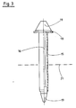
- the puncture cannula 1 has one at its rear end Insertion funnel 13 with stop plate 14 on the end, which the insertion of the puncture needle 5 and the below to be described sleeve piece 15 should facilitate.
- the puncture needle 5 After puncturing, the puncture needle 5 is removed from the Puncture cannula 1 pulled out, the latter in the body remains. When the puncture needle 5 is pulled out, the Connection between the tongues 10 of the puncture cannula 1.
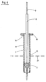
- a sleeve piece 15 with inserted therein Insertion aid 16 via the insertion funnel 13 in the Puncture cannula 1 inserted, as shown in Figure 4 is.
- the insertion aid 16 points according to FIG Position a protruding from the front end of the sleeve, rounded frusto-conical tip 17.
- the sleeve piece 15 is on its rear End with a stop plate 18 pointing radially outwards provided, against which the insertion aid 16 in the inserted Position in the sleeve piece 15 rests with its grip part 19.
- the insertion aid 16 is then pulled out and the probe 3 brought in.
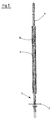
- the Probe 3 with its tube 7 through passage 6 one tubular pushing aid 8 passed until the Retaining plate 2 of the probe at the front end of the pushing aid 8 is present.
- the pushing aid 8 with the retaining plate 2 first inserted into the sleeve piece 15, as shown in Figure 6 is shown.
- the silicone material lays down existing elastic retaining plate 2 opposite the Slide direction to the rear so that the Retaining plate 2 within the sleeve piece 15 easily is possible without tissue in the area outside the Puncture point is injured.
- the probe 3 is through slow pull at the distal end of the thread placed intragastral.
- the puncture cannula 1, the sleeve piece 15 and / or the Insertion aid 16 are preferably made of plastic. From Metal existing puncture needle 5 is the one Guide point 11 for the tongues 10 of the puncture cannula 1 having plastic part arranged at the rear end Grip 20 held.
Landscapes
- Health & Medical Sciences (AREA)
- Life Sciences & Earth Sciences (AREA)
- Surgery (AREA)
- Animal Behavior & Ethology (AREA)
- General Health & Medical Sciences (AREA)
- Public Health (AREA)
- Veterinary Medicine (AREA)
- Nuclear Medicine, Radiotherapy & Molecular Imaging (AREA)
- Pathology (AREA)
- Gastroenterology & Hepatology (AREA)
- Engineering & Computer Science (AREA)
- Biomedical Technology (AREA)
- Heart & Thoracic Surgery (AREA)
- Medical Informatics (AREA)
- Molecular Biology (AREA)
- Media Introduction/Drainage Providing Device (AREA)
- Surgical Instruments (AREA)
Description
- Figur 1
- einen Halbschnitt in Längsrichtung durch eine mögliche Ausführungsform der erfindungsgemäßen Punktionskanüle mit eingesteckter Punktionsnadel,
- Figur 2
- einen Querschnitt längs der Schnittlinie 2-2 gemäß Figur 1,
- Figur 3
- einen Halbschnitt in Längsrichtung einer möglichen Ausführungsform eines erfindungsgemäßen Hülsenstückes mit eingesteckter Einführhilfe,
- Figur 4
- einen Halbschnitt in Längsrichtung durch die Punktionskanüle mit eingestecktem Hülsenteil und Einführhilfe,
- Figur 5
- einen Längsschnitt durch eine mögliche Ausführungsform einer erfindungsgemäßen Schiebehilfe mit Sonde,
- Figur 6
- einen Längsschnitt durch die Punktionskanüle mit eingeschobener Schiebehilfe mit Sonde und
- Figur 7
- eine fertig plazierte Sonde.
- 1
- - Punktionskanüle
- 2
- - Rückhalteplatte
- 3
- - Sonde, Instrument
- 4
- - Durchführung
- 5
- - Punktionsnadel
- 6
- - Durchgang
- 7
- - Instrumentenschlauch
- 8
- - Schiebehilfe
- 9
- - Längsschlitze
- 10
- - Zungen
- 11
- - Führung, Steg
- 12
- - Seitenrand
- 13
- - Einführtrichter
- 14
- - Anschlagplatte
- 15
- - Hülsenstück
- 16
- - Einführhilfe
- 17
- - Spitze
- 18
- - Anschlagplatte
- 19
- - Griffteil
- 20
- - Griffstück
- 21
- - Mageninnenwand
Claims (13)
- Applikationsbesteck in Kombination mit einem schlauch- oder röhrenförmigen Instrument (3) mit einem Instrumentenschlauch, wie Sonden, Katheter o. dgl., zur chirurgischen oder therapeutischen Behandlung des menschlichen oder tierischen Körpers oder zur Anwendung im Diagnostizierverfahren, wobei das Applikationsbesteck eine Punktionskanüle (1) mit einer Durchführung (4) mit wenigstens einem Längsschlitz (9) aufweist, dadurch gekennzeichnet, daß das Applikationsbesteck eine in die Punktionskanüle (1) verschieblich aufgenommene Punktionsnadel (5) aufweist, daß das Instrument (3) eine elastische Rückhalteplatte (2) aufweist, wobei das Instrument (3) nach Entfernen der Punktionsnadel (5) mit seiner Rückhalteplatte (2) voran mittels einer einen Durchgang (6) für den Instrumentenschlauch (7) aufweisenden Schiebehilfe (8) durch die Punktionskanüle (1) unter radialem Aufweiten ihrer längstgeschlitzten Durchführung (4) schiebbar und somit in den Körper einführbar ist.
- Applikationsbesteck nach Anspruch 1, dadurch gekennzeichnet, daß die Punktionskanüle (1) im Bereich ihres Schaftes (4), vorzugsweise vier Längsschlitze mit am vorderen Ende der Punktionskanüle (1) angeordneten Sollbruchstellen aufweist, welche beim Durchschieben der Schiebehilfe (8) mit Rückhalteplatte (2) unter Aufspreizen der durch die Längsschlitze gebildeten segmentförmigen Zungen aufbrechen.
- Applikationsbesteck nach Anspruch 1, dadurch gekennzeichnet, daß die Punktionskanüle (1) im Bereich ihres Schaftes (4), vorzugsweise vier Längsschlitze (9) aufweist, wobei durch die Längsschlitze (9) gebildeten segmentförmigen Zungen (10) mittels umfangsseitig der Punktiemadel (5) gebildeten Führungen (11) zusammengehalten und beim Einführen der Schiebehilfe (8) mit der Rückhalteplatte (2) aufspreizbar sind.
- Applikationsbesteck nach Anspruch 3, dadurch gekennzeichnet, daß die Führungen an der Punktiernadel (5) als nach radial außen vorstehende, in Längsrichtung der Punktionsnadel (5) verlaufende Führungsstege (11) ausgebildet sind, welche sich mit den dazwischen zu liegen kommenden Zungen (10) zu einer i. w. geschlossenen zylindrischen Außenmantelfläche ergänzen.
- Applikationsbesteck nach Anspruch 3 oder 4, dadurch gekennzeichnet, daß die Führungsstege (11) i. w. T-förmig ausgebildet und von den Zungen (10) mit etwa stufenförmig abgesetzten Seitenrändern (12) hintergreifbar sind.
- Applikationsbesteck nach einem der Ansprüche 1 bis 5, dadurch gekennzeichnet, daß die Punktionskanüle (1) an ihrem hinteren Ende einen Einführtrichter (13) aufweist.
- Applikationsbesteck nach einem der Ansprüche 2 bis 5, dadurch gekennzeichnet, daß sich die Längsschlitze (9) der Punktionskanüle (1) über den Einführtrichter (13) bis zu einer am hinteren Ende der Punktionskanüle (1) angeordneten Anschlagplatte (14) erstrecken.
- Applikationsbesteck nach einem der Ansprüche 1 bis 7, dadurch gekennzeichnet, daß die Schiebehilfe (8) als Rohrstück ausgebildet.
- Applikationsbesteck nach einem der Ansprüche 1 bis 8, dadurch gekennzeichnet, daß in die Punktionskanüle (1) ein Hülsenstück (15) mit einem dem eingangsseitigen Durchmesser des Einführtrichters (13) i. w. entsprechenden Außendurchmesser einschiebbar ist, in welches die Schiebehilfe (8) mit Rückhalteplatte (2) des Instrumentes (3) einführbar ist.
- Applikationsbesteck nach Anspruch 9, dadurch gekennzeichnet, daß zum Einführen des Hülsenstückes (15) die Punktionskanüle (1) eine in das Hülsenstück (15) einschiebbare Einführhilfe (16) vorgesehen ist, welche in eingeschobener Stellung eine aus dem vorderen Hülsenende vorstehende, vorzugsweise abgerundete kegelstumpfförmige Spitze (17) aufweist.
- Applikationsbesteck nach Anspruch 9 oder 10, dadurch gekennzeichnet, daß das Hülsenstück (15) an seinem hinteren Ende eine radial nach außen weisende Anschlagplatte (18) aufweist, gegen welche die Einführhilfe (16) in eingeschobener Stellung in dem Hülsenstück (15) mit ihrem Griffteil (19) anliegt.
- Applikationsbesteck nach einem der vorhergehenden Ansprüche, dadurch gekennzeichnet, daß die Punktionskanüle (1), das Hülsenstück (15), die Einführhilfe (16) und/oder die Schiebehilfe (8) aus Kunststoff bestehen.
- Applikationsbesteck nach einem der vorhergehenden Ansprüche, dadurch gekennzeichnet, daß die Punktionsnadel (5) an einen die Führungen (11) für die Zungen (10) der Punktionskanüle (1) aufweisenden Kunststoffteil mit am hinteren Ende angeordnetem Griffstück (20) gehalten ist.
Applications Claiming Priority (2)
| Application Number | Priority Date | Filing Date | Title |
|---|---|---|---|
| DE4317754 | 1993-05-28 | ||
| DE4317754 | 1993-05-28 |
Publications (2)
| Publication Number | Publication Date |
|---|---|
| EP0630618A1 EP0630618A1 (de) | 1994-12-28 |
| EP0630618B1 true EP0630618B1 (de) | 1998-12-02 |
Family
ID=6489112
Family Applications (1)
| Application Number | Title | Priority Date | Filing Date |
|---|---|---|---|
| EP94108239A Expired - Lifetime EP0630618B1 (de) | 1993-05-28 | 1994-05-27 | Applikationsbesteck für Katheter o.dgl. |
Country Status (3)
| Country | Link |
|---|---|
| EP (1) | EP0630618B1 (de) |
| DE (1) | DE59407368D1 (de) |
| ES (1) | ES2126675T3 (de) |
Families Citing this family (3)
| Publication number | Priority date | Publication date | Assignee | Title |
|---|---|---|---|---|
| US5628753A (en) * | 1995-06-01 | 1997-05-13 | Sandoz Nutrition Ltd. | Gastrostomy tube removal tool |
| US6030364A (en) * | 1997-10-03 | 2000-02-29 | Boston Scientific Corporation | Apparatus and method for percutaneous placement of gastro-intestinal tubes |
| CN113974723B (zh) * | 2021-11-24 | 2024-06-18 | 河南印何阗生物科技有限公司 | 可视脑深部手术穿刺引流牵开导引导管 |
Family Cites Families (5)
| Publication number | Priority date | Publication date | Assignee | Title |
|---|---|---|---|---|
| GB8316640D0 (en) * | 1983-06-18 | 1983-07-20 | Gill S S | Introducing drainage tubing scopes/instruments into cavities |
| GB8424436D0 (en) * | 1984-09-27 | 1984-10-31 | Pratt Int Ltd Burnerd | Surgical appliance |
| DE3713828A1 (de) * | 1987-04-24 | 1988-11-10 | Frimberger Erintrud | Vorrichtung zum plazieren einer durchfuehrungshuelse, insbesondere trokarhuelse, an der aussenwand des menschlichen oder tierischen koerpers und darin angeordneten hohlen organen |
| US5074846A (en) * | 1990-09-13 | 1991-12-24 | Abbott Laboratories | Stoma creator gastrostomy device and method for placement of a feeding tube |
| US5112310A (en) * | 1991-02-06 | 1992-05-12 | Grobe James L | Apparatus and methods for percutaneous endoscopic gastrostomy |
-
1994
- 1994-05-27 EP EP94108239A patent/EP0630618B1/de not_active Expired - Lifetime
- 1994-05-27 ES ES94108239T patent/ES2126675T3/es not_active Expired - Lifetime
- 1994-05-27 DE DE59407368T patent/DE59407368D1/de not_active Expired - Lifetime
Also Published As
| Publication number | Publication date |
|---|---|
| DE59407368D1 (de) | 1999-01-14 |
| EP0630618A1 (de) | 1994-12-28 |
| ES2126675T3 (es) | 1999-04-01 |
Similar Documents
| Publication | Publication Date | Title |
|---|---|---|
| EP0679408B1 (de) | Vorrichtung zum Einführen eines Katheters in einen Körperhohlraum | |
| EP0667763B1 (de) | Set zur schaffung eines künstlichen mageneingangs | |
| DE602004011568T2 (de) | Gerät zur abgabe von hämostatischen dichtungsmitteln | |
| DE69427901T2 (de) | Kathetersystem für die gastrostomie | |
| DE69737897T2 (de) | Nähgerät von Blutgefässen | |
| DE69228257T2 (de) | Halter für chirurgische instrumente | |
| DE69123982T2 (de) | Dehnung aufrechterhaltendes führungselement sowie dilatator | |
| DE69408630T2 (de) | Trokar und Trokarkatheter für Drainage | |
| EP0256546B1 (de) | Vorrichtung zum Plazieren eines Ernährungs-Schlauches am Magen des menschlichen oder tierischen Körpers | |
| DE69323084T2 (de) | Vorrichtung zum setzen eines katheters | |
| DE69410148T2 (de) | Kathetereinführungsvorrichtung mit verbessertem Nadelgreifglied | |
| DE102013101538B3 (de) | Set für die periphere Nervenblockade | |
| WO2007147439A1 (de) | Vorrichtung zum einführen und positionieren von chirurgischen instrumenten und entsprechendes verfahren | |
| DE102005021470A1 (de) | Einführhilfe für die perkutane Tracheostomie | |
| EP0433717A1 (de) | Punktionsbesteck | |
| DE4204210A1 (de) | Extraktionsbeutel fuer die endoskopische chirurgie | |
| EP2952222A1 (de) | Ballonkatheter mit einer Einführhilfe für einen Führungsdraht | |
| DE68924518T2 (de) | Biegbarer Trokar. | |
| EP0630618A1 (de) | Applikationsbesteck für Katheter o.dgl. | |
| DE102016111647B4 (de) | Punktionskatheter | |
| DE2922511A1 (de) | Abdominaler injektor | |
| WO2004000410A1 (de) | Dilatator | |
| DE19706529C2 (de) | Perkutanes vaskuläres Verschlußsystem | |
| DE2050805A1 (de) | Gerät zum Einsetzen eines Katheters | |
| DE102022121987B3 (de) | Medizinisches Instrument |
Legal Events
| Date | Code | Title | Description |
|---|---|---|---|
| PUAI | Public reference made under article 153(3) epc to a published international application that has entered the european phase |
Free format text: ORIGINAL CODE: 0009012 |
|
| AK | Designated contracting states |
Kind code of ref document: A1 Designated state(s): DE ES FR GB IT |
|
| 17P | Request for examination filed |
Effective date: 19950121 |
|
| 17Q | First examination report despatched |
Effective date: 19970627 |
|
| GRAG | Despatch of communication of intention to grant |
Free format text: ORIGINAL CODE: EPIDOS AGRA |
|
| GRAG | Despatch of communication of intention to grant |
Free format text: ORIGINAL CODE: EPIDOS AGRA |
|
| GRAH | Despatch of communication of intention to grant a patent |
Free format text: ORIGINAL CODE: EPIDOS IGRA |
|
| GRAH | Despatch of communication of intention to grant a patent |
Free format text: ORIGINAL CODE: EPIDOS IGRA |
|
| GRAA | (expected) grant |
Free format text: ORIGINAL CODE: 0009210 |
|
| AK | Designated contracting states |
Kind code of ref document: B1 Designated state(s): DE ES FR GB IT |
|
| GBT | Gb: translation of ep patent filed (gb section 77(6)(a)/1977) |
Effective date: 19981202 |
|
| REF | Corresponds to: |
Ref document number: 59407368 Country of ref document: DE Date of ref document: 19990114 |
|
| ITF | It: translation for a ep patent filed | ||
| ET | Fr: translation filed | ||
| REG | Reference to a national code |
Ref country code: ES Ref legal event code: FG2A Ref document number: 2126675 Country of ref document: ES Kind code of ref document: T3 |
|
| PGFP | Annual fee paid to national office [announced via postgrant information from national office to epo] |
Ref country code: GB Payment date: 19990521 Year of fee payment: 6 |
|
| PGFP | Annual fee paid to national office [announced via postgrant information from national office to epo] |
Ref country code: ES Payment date: 19990528 Year of fee payment: 6 |
|
| PLBE | No opposition filed within time limit |
Free format text: ORIGINAL CODE: 0009261 |
|
| STAA | Information on the status of an ep patent application or granted ep patent |
Free format text: STATUS: NO OPPOSITION FILED WITHIN TIME LIMIT |
|
| 26N | No opposition filed | ||
| PG25 | Lapsed in a contracting state [announced via postgrant information from national office to epo] |
Ref country code: GB Free format text: LAPSE BECAUSE OF NON-PAYMENT OF DUE FEES Effective date: 20000527 |
|
| PG25 | Lapsed in a contracting state [announced via postgrant information from national office to epo] |
Ref country code: ES Free format text: THE PATENT HAS BEEN ANNULLED BY A DECISION OF A NATIONAL AUTHORITY Effective date: 20000529 |
|
| GBPC | Gb: european patent ceased through non-payment of renewal fee |
Effective date: 20000527 |
|
| PG25 | Lapsed in a contracting state [announced via postgrant information from national office to epo] |
Ref country code: FR Free format text: LAPSE BECAUSE OF NON-PAYMENT OF DUE FEES Effective date: 20010131 |
|
| REG | Reference to a national code |
Ref country code: FR Ref legal event code: ST |
|
| REG | Reference to a national code |
Ref country code: ES Ref legal event code: FD2A Effective date: 20020204 |
|
| PG25 | Lapsed in a contracting state [announced via postgrant information from national office to epo] |
Ref country code: IT Free format text: LAPSE BECAUSE OF NON-PAYMENT OF DUE FEES;WARNING: LAPSES OF ITALIAN PATENTS WITH EFFECTIVE DATE BEFORE 2007 MAY HAVE OCCURRED AT ANY TIME BEFORE 2007. THE CORRECT EFFECTIVE DATE MAY BE DIFFERENT FROM THE ONE RECORDED. Effective date: 20050527 |
|
| PG25 | Lapsed in a contracting state [announced via postgrant information from national office to epo] |
Ref country code: FR Free format text: LAPSE BECAUSE OF NON-PAYMENT OF DUE FEES Effective date: 19990531 |
|
| PGFP | Annual fee paid to national office [announced via postgrant information from national office to epo] |
Ref country code: DE Payment date: 20130529 Year of fee payment: 20 |
|
| REG | Reference to a national code |
Ref country code: DE Ref legal event code: R071 Ref document number: 59407368 Country of ref document: DE |
|
| PG25 | Lapsed in a contracting state [announced via postgrant information from national office to epo] |
Ref country code: DE Free format text: LAPSE BECAUSE OF EXPIRATION OF PROTECTION Effective date: 20140528 |