EP0629551B1 - Method and apparatus for wrapping articles - Google Patents
Method and apparatus for wrapping articles Download PDFInfo
- Publication number
- EP0629551B1 EP0629551B1 EP94830290A EP94830290A EP0629551B1 EP 0629551 B1 EP0629551 B1 EP 0629551B1 EP 94830290 A EP94830290 A EP 94830290A EP 94830290 A EP94830290 A EP 94830290A EP 0629551 B1 EP0629551 B1 EP 0629551B1
- Authority
- EP
- European Patent Office
- Prior art keywords
- wrapping
- conveyor
- article
- piece
- bar
- Prior art date
- Legal status (The legal status is an assumption and is not a legal conclusion. Google has not performed a legal analysis and makes no representation as to the accuracy of the status listed.)
- Expired - Lifetime
Links
- 238000000034 method Methods 0.000 title claims description 12
- 239000000463 material Substances 0.000 claims description 78
- 238000011144 upstream manufacturing Methods 0.000 claims description 9
- 230000001360 synchronised effect Effects 0.000 claims description 2
- 230000007423 decrease Effects 0.000 claims 1
- 230000032258 transport Effects 0.000 description 14
- 230000007480 spreading Effects 0.000 description 6
- 230000000694 effects Effects 0.000 description 5
- 230000008901 benefit Effects 0.000 description 3
- 230000008859 change Effects 0.000 description 3
- 238000004519 manufacturing process Methods 0.000 description 2
- 230000000254 damaging effect Effects 0.000 description 1
- 230000007613 environmental effect Effects 0.000 description 1
- 239000002654 heat shrinkable material Substances 0.000 description 1
- 230000007246 mechanism Effects 0.000 description 1
- 230000009467 reduction Effects 0.000 description 1
- 230000002522 swelling effect Effects 0.000 description 1
Images




Classifications
-
- B—PERFORMING OPERATIONS; TRANSPORTING
- B65—CONVEYING; PACKING; STORING; HANDLING THIN OR FILAMENTARY MATERIAL
- B65B—MACHINES, APPARATUS OR DEVICES FOR, OR METHODS OF, PACKAGING ARTICLES OR MATERIALS; UNPACKING
- B65B11/00—Wrapping, e.g. partially or wholly enclosing, articles or quantities of material, in strips, sheets or blanks, of flexible material
- B65B11/06—Wrapping articles, or quantities of material, by conveying wrapper and contents in common defined paths
- B65B11/08—Wrapping articles, or quantities of material, by conveying wrapper and contents in common defined paths in a single straight path
- B65B11/10—Wrapping articles, or quantities of material, by conveying wrapper and contents in common defined paths in a single straight path to fold the wrappers in tubular form about contents
Definitions
- the present invention has, as a subject, a method and an apparatus for transporting a piece of wrapping material during the article wrapping phase in a machine for wrapping articles with pieces of wrapping material, particularly heat-shrinkable material.
- the above mentioned wrapping machine generally and basically comprises:
- reference numeral 1 indicates the article feeding conveyor
- reference numeral 2 indicates the conveyor along which the wrapping of the articles is performed
- reference numeral 3 indicates the wrapped article receiving conveyor.
- Reference numeral 4 indicates endless transport means which carry, for instance, two wrapping bars indicated by 5a and 5b.
- the wrapping material feeding means are referred to as 6, while the wrapping material pieces are indicated by the numerals 7a and 7b.
- the articles to be wrap packaged are referred to as 8a and 8b.
- an article 8a to be wrap packaged is being transferred from the conveyor 1 to the conveyor 2.
- the whole article is placed on the conveyor 2 with the leading part of the wrapping material piece situated between the bottom of the article 8a and the transport surface of the conveyor 2, while the wrapping bar 5a, suitably synchronised, intercepts the wrapping material piece 7a in its intermediate region.
- the wrapping bar 5a has begun the transport of wrapping material piece 7a so that to set the same around the article.
- the article 8a is moved forward and the transfer of the subsequent article 8b from the conveyor 1 to the conveyor 2 can take place only when the rear extremity of the wrapping material piece 7a is beyond the inlet end of the conveyor 2, so that the leading end of the said subsequent article 8b does not push the rear extremity of the wrapping material piece 7a against the conveyor 2, thus preventing a correct flowing of the wrapping material piece 7a pulled by the bar 5a.
- the distance between the precedent package 8a and the subsequent package 8b must be in relation with the length of the wrapping material piece.
- This distance determines the feeding step of the articles 8a, 8b, etc., defining the production capacity of the wrapping machine.
- the recent embodiment illustrated in figures 4 and 4a, provides for early withdrawing of the rear part of wrapping material piece 7a, so that the step between the articles may be reduced in order to increase the productive capacity of the wrapping machine.
- the substantial difference between the two embodiments lies in the fact that the close loop path in the endless transport means has the upper path considerably higher than the top of the article to be wrapped.
- Such embodiment presents many drawbacks, the first of which results from the fact that during the phases of wrapping the article, the part of wrapping material piece comprised between the wrapping bar 5a and the top of the article, due to its forward advancement, fills with air and swells, causing a longitudinal tension that sometimes can withdraw the lead extremity of the wrapping material piece from under the article, specially with articles of limited weight.
- a further disadvantage of such embodiment that prevents a correct spreading of the wrapping material piece around the article 8a is due to the long distance of the wrapping bar 5a from the surface of the article to be wrapped.
- the main object of the present invention is therefore to avoid the drawbacks reported above.
- the invention resolves the problem of finding out a method and producing apparatus for transport of the wrapping material piece during the wrapping phase of articles in a machine for wrapping articles with wrapping material pieces.
- the first advantage of the present invention is that the articles to be wrapped can be positioned closer one to another, thus reducing the step, since the rear of the wrapping material piece is withdrawn earlier from between the feeding and wrapping conveyors, and the machine productive capacity increases.
- Another advantage of the present invention is a better spreading of the wrapping material piece around the article in the phase of wrapping of the latter and the possibility to use the above mentioned machine in any environmental conditions and/or with any type of wrapping material and/or any length of wrapping material piece, since damaging effects resulting from a wrapping bar that is far from the surfaces to wrap and/or effects resulting from adherence of the wrapping material pieces one to another are avoided.
- the wrapping machine is constituted by a base 10 that carries a first conveyor 11 designed to support and feed, in single sequence, articles 14 to a second conveyor 12 on which the same articles are wrapped; and by a third conveyor 13 that receives the articles from the second conveyor 12 and that complete the wrapping thereof.
- a conveyor 15 designed to feed, in single sequence, wrapping material pieces 16, putting their leading end over the up-stream end of the second conveyor 12.
- a frame 17 including two uprights 17a, 17b, arranged in a mirror-like manner on the sides of the conveyor12 and extending therealong.
- Each upright 17a, 17b, e.g. 17b defines a pair of sliding guides 18b, 19b, destined to guide respective chains 20b, 21b, each of which transports one end of respective plurality of wrapping bars 22a, 22b and 23a, 23b, only two of them being present in the indicated example.
- Said chains 20a-21a, 20b-21b are moved by respective chain supporting wheels 24a-25a and 24b-25b that are keyed on a common driving shaft 26.
- the bars 22 describe a first orbit 27, contained in a vertical plane circumscribing the conveyor 12; while the bars 23 describe a second longer orbit 28, contained in a vertical plane preferably parallel to the previous one, and circumscribing the conveyor 12.
- said orbits 27 and 28 have a path I-II substantially coincident, a path II-III first divergent and then convergent, a path III-IV substantially coincident, and a path IV-I first divergent and then convergent; this causes the change of the relative distance between the single bars 22, 23 during circulation of each pair of bars 22a-23a, 22b-23b.
- Such changeable relative distance is obtained by making the orbital path 27 shorter than the orbital path 28, and, simultaneously, the pitch line of the driving wheel 24 shorter than the one of the wheel 25, and making both wheels 24 and 25 rotate with the same angular speed in order to compensate the difference of the path of the chains 20, 21.
- the wrapping machine is also equipped with a kinematic mechanism (not shown because it is not part of the subject of the present invention) such that it synchronises the movements of the three conveyors 11, 12, 13, of the carrier 15, and of the shaft 26 so as to obtain a synchronisation for the proceeding articles 14, for the wrapping material pieces 16 being fed and for the pair of wrapping bars 22, 23.
- a kinematic mechanism not shown because it is not part of the subject of the present invention
- the wrapping machine feeds the articles 14a, 14b to the conveyor 12 by the conveyor 11 in a sequence.
- an article 14a is situated over the two conveyors 11 and 12, and the leading extremity of a wrapping material piece 16a is so placed as to result interposed between the bottom of the same article 14a and the transport surface of the conveyor 12.
- the leading extremity of the wrapping material piece 16a is interposed between the bottom of the article 14a and the transport surface of the conveyor 12; when the whole article 14a is on the conveyor 12, the wrapping bar 22a comes into contact with the wrapping material piece being fed, while the bar 23a remains slightly behind.
- the bar 22a is spreading the wrapping material piece 16a on the back facing of the article.
- the bar 23a also interposed between the two conveyors 11 and 12, has come in contact with and raised the wrapping material piece.
- a subsequent article 14b is situated on the conveyor 11 behind the article 14a and is moved towards the conveyor 12 by the same conveyor 11.
- the wrapping material piece 16a is carried and transported by the bars 22a, 23a that define its linear segmented configuration.
- the segmented conformation of the figure 11 prevents the contact or overlapping of the parts of the wrapping material piece behind and before the bar 22, thus eliminating the undesired effects reported earlier; while, comparing with the figure 4a, also illustrating the known technique, the wrapping bar appears to be close to the upper facing of the article, avoiding the disadvantages reported earlier.
- the bar 22a together with the bar 23a, has partially wrapped the article 14a and has made the rear extremity of the wrapping material piece 16a to pass between the conveyors 12 and 13, then positioning it below the transport surface of the same.
- the subsequent article 14b is placed on the conveyors 11 and 12, the leading extremity of a subsequent wrapping material piece 16b is situated below the bottom of the same article and the transport surface of the conveyor 12; a subsequent pair of wrapping bars 22b, 23b, moving in phase relation with the same article 14b that is now proceeding as well as with the wrapping material piece 16b being fed, are going in contact with the wrapping material piece; the conditions illustrated in figure 7 relative to the article 14a, are thus repeated and the operating cycle may take place again.
- the article 14a is being transported from the conveyor 12 to the conveyor 13 and in said passage the rear extremity of the wrapping material piece 16a is placed below the leading extremity of the same wrapping material piece 16a, thus completing the wrapping of the same article 14a.
- the article 14b proceeds and, as for the precedent article, the leading extremity of a subsequent wrapping material piece 16b has been interposed between the bottom of the article and the transport surface of the conveyor 12.
Landscapes
- Engineering & Computer Science (AREA)
- Mechanical Engineering (AREA)
- Basic Packing Technique (AREA)
- Auxiliary Devices For And Details Of Packaging Control (AREA)
Description
- The present invention has, as a subject, a method and an apparatus for transporting a piece of wrapping material during the article wrapping phase in a machine for wrapping articles with pieces of wrapping material, particularly heat-shrinkable material.
- Presently, as described in the patents US-A-3.791.100, US-A-5.203.144 and US-A-5.203.146, these last two patents being owned by the applicant of this patent application, the above mentioned wrapping machine generally and basically comprises:
- a first conveyor, designed for supporting the articles to be wrapped and to feed them one by one to a second conveyor;
- a second wrapping phase conveyor having an inlet end, an outlet end, and an upper surface situated between the above mentioned inlet and outlet ends, this upper surface being aimed at supporting and conveying articles while being wrap packaged in succession;
- means for feeding the wrapping material, designed to feed single pieces of wrapping material, in succession, to the above mentioned wrapping phase conveyor, placing the lead extremity of each wrapping material piece on top of the upper surface of the above mentioned wrapping phase conveyor, at the inlet end thereof;
- wrapping means comprising an endless conveyor carrying at least one wrapping bar along a path surrounding the above mentioned wrapping phase conveyor, these wrapping means being designed to set the above mentioned heat-shrinkable wrapping material pieces over and in front of each article being wrapped, then placing the rear extremity of the above mentioned wrapping material piece in a region between the above mentioned wrapping phase conveyor and the upstream end of a third receiving conveyor;
- a third receiving conveyor, for receiving and supporting the articles partially wrapped, aimed at placing the rear extremity of the wrapping material piece under the lead extremity of the same wrapping material piece;
- synchronising means, designed to set in proper time relation the motion of the above mentioned first conveyor, the motion of the above mentioned second conveyor, said means for feeding the wrapping material, said endless transport means and the related wrapping bar, and the motion of the above mentioned third receiving conveyor.
- These machines, made as explained hitherto, are affected by several drawbacks as far as the transport of the wrapping material piece is concerned, as performed by the wrapping bar endless transport means.
- These drawbacks affect negatively the production rate, as well as the correct and harmonious settlement of the wrapping material piece.
- With reference to figures 1, 2, 3, 3a and 3b of the drawings attached hereto, which show subsequent sequences concerning the main operative stages in which an article is wrapped while being made to advance, in accordance with the known method as described hereinabove,
reference numeral 1 indicates the article feeding conveyor,reference numeral 2 indicates the conveyor along which the wrapping of the articles is performed whilereference numeral 3 indicates the wrapped article receiving conveyor. -
Reference numeral 4 indicates endless transport means which carry, for instance, two wrapping bars indicated by 5a and 5b. - The wrapping material feeding means are referred to as 6, while the wrapping material pieces are indicated by the
numerals 7a and 7b. - The articles to be wrap packaged are referred to as 8a and 8b.
- Referring now to Figure 1, an
article 8a to be wrap packaged, is being transferred from theconveyor 1 to theconveyor 2. - Meanwhile the wrapping
material piece 7a is fed by theconveyor 6, which places the leading edge of the same wrapping material piece between the bottom of thearticle 8 and theconveyor 2. - Referring now to figure 2, the whole article is placed on the
conveyor 2 with the leading part of the wrapping material piece situated between the bottom of thearticle 8a and the transport surface of theconveyor 2, while thewrapping bar 5a, suitably synchronised, intercepts the wrappingmaterial piece 7a in its intermediate region. - Referring to figure 3, the
wrapping bar 5a has begun the transport of wrappingmaterial piece 7a so that to set the same around the article. - Referring to figure 3a, the
article 8a is moved forward and the transfer of thesubsequent article 8b from theconveyor 1 to theconveyor 2 can take place only when the rear extremity of the wrappingmaterial piece 7a is beyond the inlet end of theconveyor 2, so that the leading end of the saidsubsequent article 8b does not push the rear extremity of the wrappingmaterial piece 7a against theconveyor 2, thus preventing a correct flowing of the wrappingmaterial piece 7a pulled by thebar 5a. - For this reason, the distance between the
precedent package 8a and thesubsequent package 8b must be in relation with the length of the wrapping material piece. - This distance determines the feeding step of the
articles - Referring now to fig 3b, it is noted that, during setting of the wrapping
material piece 7a by thebar 5a, the part of the same wrappingmaterial piece 7a being at the back of thebar 5a touches the part of the wrappingmaterial piece 7a being before thesame bar 5a, thus provoking adherence of the two contacting surfaces. - This adherence, in its turn, brings about undesired creeping effects resulting principally from the feature of the same wrapping material to charge electrostatically.
- In particular environment situations, such effects could not allow for the correct spreading of the wrapping material piece thus making it impossible to use the machine with particular types of wrapping material or with particular lengths of the wrapping material pieces.
- The recent embodiment, illustrated in figures 4 and 4a, provides for early withdrawing of the rear part of wrapping
material piece 7a, so that the step between the articles may be reduced in order to increase the productive capacity of the wrapping machine. - The substantial difference between the two embodiments lies in the fact that the close loop path in the endless transport means has the upper path considerably higher than the top of the article to be wrapped.
- Such embodiment presents many drawbacks, the first of which results from the fact that during the phases of wrapping the article, the part of wrapping material piece comprised between the
wrapping bar 5a and the top of the article, due to its forward advancement, fills with air and swells, causing a longitudinal tension that sometimes can withdraw the lead extremity of the wrapping material piece from under the article, specially with articles of limited weight. - Another drawback of the above mentioned embodiment, results from the fact that the wrapping bar must be moved much quicker because of its longer path, thus the aforementioned swelling effect is increased and a correct and harmonious spreading of the wrapping material piece may be obstructed.
- A further disadvantage of such embodiment that prevents a correct spreading of the wrapping material piece around the
article 8a is due to the long distance of thewrapping bar 5a from the surface of the article to be wrapped. - The last drawback, already pointed out in the previous embodiment, with reference to figure 4a, results from the fact that the part of the wrapping
material piece 7a that is behind thewrapping bar 5a touches the part of the wrappingmaterial piece 7a that is before thewrapping bar 5a causing the same undesired effects, already described in the first embodiment. - The main object of the present invention is therefore to avoid the drawbacks reported above.
- The invention, such as characterised by the claims, resolves the problem of finding out a method and producing apparatus for transport of the wrapping material piece during the wrapping phase of articles in a machine for wrapping articles with wrapping material pieces.
- The following results are obtained by the use of a method and an apparatus of this type:
- the rear extremity of the wrapping material piece is withdrawn earlier from the upstream end of the conveyor thus freeing earlier the zone between the feeding conveyor and the wrapping conveyor;
- the part of the wrapping material piece behind the wrapping bar does not touch the part before the wrapping bar;
- the wrapping bar can move close to the surfaces to be wrapped;
- the speed of wrapping bar is a bit higher that the advancement speed of the article to be wrapped.
- The first advantage of the present invention is that the articles to be wrapped can be positioned closer one to another, thus reducing the step, since the rear of the wrapping material piece is withdrawn earlier from between the feeding and wrapping conveyors, and the machine productive capacity increases.
- Another advantage of the present invention is a better spreading of the wrapping material piece around the article in the phase of wrapping of the latter and the possibility to use the above mentioned machine in any environmental conditions and/or with any type of wrapping material and/or any length of wrapping material piece, since damaging effects resulting from a wrapping bar that is far from the surfaces to wrap and/or effects resulting from adherence of the wrapping material pieces one to another are avoided.
- Further characteristics and advantages of the present invention will be better pointed out in the following detailed description of the preferred embodiment, given here as a mere example, not limitative, with reference to the enclosed drawings, in which:
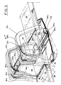
- Figure 5 is a perspective view of the apparatus being the subject of the present invention, incorporated in a section of the wrapping machine, designed to wrap the articles;
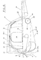
- Figure 6 is a schematic lateral view of the apparatus, in which the current operative phase is shown with continuous line and the precedent and subsequent phases are drafted with dotted line;
- Figures from 7 to 13 show a schematic view of some operative phases of the wrapping of an article.
- With reference to the accompanying figures, in particular to figures 5 and 6, the wrapping machine is constituted by a
base 10 that carries afirst conveyor 11 designed to support and feed, in single sequence,articles 14 to asecond conveyor 12 on which the same articles are wrapped; and by athird conveyor 13 that receives the articles from thesecond conveyor 12 and that complete the wrapping thereof. - Below said machine there is a
conveyor 15 designed to feed, in single sequence, wrappingmaterial pieces 16, putting their leading end over the up-stream end of thesecond conveyor 12. - Astride the
second conveyor 12, and near to it, there is aframe 17 including two uprights 17a, 17b, arranged in a mirror-like manner on the sides of the conveyor12 and extending therealong. - Each upright 17a, 17b, e.g. 17b defines a pair of sliding guides 18b, 19b, destined to guide respective chains 20b, 21b, each of which transports one end of respective plurality of
wrapping bars - The other end of the
bars chains - Said
chains 20a-21a, 20b-21b are moved by respective chain supporting wheels 24a-25a and 24b-25b that are keyed on acommon driving shaft 26. - Thus, the bars 22-23 of each pair of
bars 22a-23a, 22b- 23b are transported together. - Arranged in the way shown in figure 6, the
bars 22 describe a first orbit 27, contained in a vertical plane circumscribing theconveyor 12; while thebars 23 describe a second longer orbit 28, contained in a vertical plane preferably parallel to the previous one, and circumscribing theconveyor 12. - Still with reference to figure 6, said orbits 27 and 28 have a path I-II substantially coincident, a path II-III first divergent and then convergent, a path III-IV substantially coincident, and a path IV-I first divergent and then convergent; this causes the change of the relative distance between the
single bars bars 22a-23a, 22b-23b. - Such changeable relative distance is obtained by making the orbital path 27 shorter than the orbital path 28, and, simultaneously, the pitch line of the
driving wheel 24 shorter than the one of thewheel 25, and making bothwheels chains - With such arrangement, it is possible to change relative distance between the
reciprocal bars bars 22a-23a, 22b-23b by shifting one of them in respect to the other; it is also possible to change the orbital speed of the pair ofbars 22a-23a, 22b-23b or the speed of a single bar in respect to the other, providing for replacement of one or both driving wheels with others of different pitch line. - The wrapping machine is also equipped with a kinematic mechanism (not shown because it is not part of the subject of the present invention) such that it synchronises the movements of the three
conveyors carrier 15, and of theshaft 26 so as to obtain a synchronisation for the proceedingarticles 14, for the wrappingmaterial pieces 16 being fed and for the pair ofwrapping bars - With reference to the figures from 7 to 13, that illustrate subsequent sequences concerning the principal operative phases of the wrapping of an article during its proceeding, the wrapping machine feeds the articles 14a, 14b to the
conveyor 12 by theconveyor 11 in a sequence. - As shown in figure 7, an article 14a is situated over the two
conveyors material piece 16a is so placed as to result interposed between the bottom of the same article 14a and the transport surface of theconveyor 12. - As shown in figure 8, the leading extremity of the wrapping
material piece 16a is interposed between the bottom of the article 14a and the transport surface of theconveyor 12; when the whole article 14a is on theconveyor 12, thewrapping bar 22a comes into contact with the wrapping material piece being fed, while the bar 23a remains slightly behind. - As shown in figure 9, the
bar 22a is spreading the wrappingmaterial piece 16a on the back facing of the article. - The bar 23a, also interposed between the two
conveyors conveyor 11 behind the article 14a and is moved towards theconveyor 12 by thesame conveyor 11. - With reference to figure 10, the rear extremity of the wrapping
material piece 16a is already over the level of theconveyors - Comparing this arrangement with the one illustrated in figure 3a, relative to the known technique, it appears that the new arrangement increases the portion of the wrapping material piece that is withdrawn, thus allowing for the reduction of the space between the articles to be wrapped; in comparison with figure 4, also related to the known technique, it appears that the wrapping bar moves close to the facings of the article, improving the spreading of the wrapping material piece thereon.
- With reference to figure 11, the wrapping
material piece 16a is carried and transported by thebars 22a, 23a that define its linear segmented configuration. - In comparison with the conformation illustrated in figure 3b, the segmented conformation of the figure 11 prevents the contact or overlapping of the parts of the wrapping material piece behind and before the
bar 22, thus eliminating the undesired effects reported earlier; while, comparing with the figure 4a, also illustrating the known technique, the wrapping bar appears to be close to the upper facing of the article, avoiding the disadvantages reported earlier. - With reference to figure 12, the
bar 22a, together with the bar 23a, has partially wrapped the article 14a and has made the rear extremity of the wrappingmaterial piece 16a to pass between theconveyors - The subsequent article 14b is placed on the
conveyors conveyor 12; a subsequent pair of wrappingbars 22b, 23b, moving in phase relation with the same article 14b that is now proceeding as well as with the wrapping material piece 16b being fed, are going in contact with the wrapping material piece; the conditions illustrated in figure 7 relative to the article 14a, are thus repeated and the operating cycle may take place again. - With reference to figure 13, the article 14a is being transported from the
conveyor 12 to theconveyor 13 and in said passage the rear extremity of the wrappingmaterial piece 16a is placed below the leading extremity of the samewrapping material piece 16a, thus completing the wrapping of the same article 14a. - The article 14b proceeds and, as for the precedent article, the leading extremity of a subsequent wrapping material piece 16b has been interposed between the bottom of the article and the transport surface of the
conveyor 12. - The description of the method and the device made with reference to the enclosed figures of drawings are given as a pure example, not limitative, and therefore it is evident that changes or variants suggested by use or practice are possible as long as they fall within the scope of the following claims.
Claims (7)
- Method for wrapping an article with a piece of wrapping material in a wrapping machine comprising:characterised in that every single wrapping material piece is transported by means of two wrapping bars (22; 23), both the first and the second (23) wrapping bar supporting said piece, and said second bar moving along a second path (28) different from said first path (27) in a vertical plane circumscribing said wrapping conveyor (12) a distance spaced behind the first bar in moving direction, the movements of said wrapping bars (22, 23) being synchronised such that the trailing edge of the piece of wrapping material is withdrawn from the upstream end of the wrapping conveyor (12) by said second wrapping bar.feeding a piece of wrapping material (16) supplied in single sequence by conveying means (15) to an upstream end of a wrapping conveyor (12) such that the leading end of said piece overlies a receiving upper surface of said wrapping conveyor;advancing an article (14) to be wrapped onto said receiving surface onto the leading end of said piece of wrapping material lying thereon from a feeding conveyor (11) upstream of said wrapping conveyor, and conveying said article along said wrapping conveyor (12);wrapping said article placed on said wrapping conveyor with a single wrapping material piece by a first wrapping bar (22) carried by wrapping means (20), during the movement of said bar (22) along a first path (27) in a vertical plane circumscribing said wrapping conveyor (12), such that the trailing edge of the wrapping material piece is brought over the article and below the upper surface of the wrapping conveyor at its downstream end so that said piece will come under the moving article at its discharge;
- Method according to claim 1, characterised in that said wrapping bars (22, 23) are displaced along the respective paths (27, 28) at different speeds.
- Method according to claim 1 or 2, characterised in that said wrapping bars (22, 23) have a relative distance which increases upon passage of said bars between said feeding conveyor (11) and said wrapping conveyor (12) and then decreases again.
- Apparatus for wrapping an article (14) with a piece of wrapping material comprising:characterised in that is comprisesa wrapping conveyor (12), which has an upstream end and a receiving upper surface, for conveying the article to be wrapped there along;conveying means (15) to supply in single sequence a piece of wrapping material (16) to said upstream end of said wrapping conveyor (12) such that the leading end of said piece overlies said receiving upper surface;a feeding conveyor (11) upstream of said wrapping conveyor (12) for advancing an article (14) onto said receiving surface such that said article is moved onto said leading end to be wrapped;a first wrapping bar (22) carried by wrapping means (20) for wrapping said article placed on said wrapping conveyor with a single wrapping material piece during the movement of said bar (22) along a first path (27) in a vertical plane circumscribing said wrapping conveyor (12), such that the trailing end of the wrapping material piece is brought over the article and below the upper surface of the wrapping conveyor at its downstream end so that said piece will come under the moving article at its discharge;a second wrapping bar (23) carried by wrapping means (21), said first and second wrapping bars together supporting and transporting every single wrapping material piece,a second path (28) in a vertical plane circumscribing said wrapping conveyor (12) different from said first path (27), said second wrapping bar capable of being moved along said second path, a distance spaced behind the first bar (22) in moving direction,synchronising means for synchronising the movement of said wrapping bars (22, 23) such that the trailing edge of the piece of wrapping material is withdrawn from the upstream end of the wrapping conveyor (12) by said second wrapping bar.
- Apparatus according to claim 4, characterised in that sliding guides (18, 19) are provided entraining said wrapping bars (22, 23) around respective closed paths (27, 28), said guides (18, 19) guiding said wrapping means, said wrapping means being chains (20, 21).
- Apparatus according to claim 4 or 5, characterised in that said guide means (18, 19) are formed on a pair of uprights (17a, 17b) of a frame (17) straddling said wrapping conveyor (12).
- Apparatus according to claim 6 characterised in that said guide means (18, 19) further comprise a double pair of toothed wheels (24, 25) keyed to a common shaft (26).
Applications Claiming Priority (2)
| Application Number | Priority Date | Filing Date | Title |
|---|---|---|---|
| ITBO930279 | 1993-06-18 | ||
| ITBO930279A IT1263438B (en) | 1993-06-18 | 1993-06-18 | METHOD AND EQUIPMENT FOR THE TRANSPORT OF THE WINDING BAND IN THE WRAPPING STAGES OF THE ITEMS IN THE MACHINES PACKING MACHINES OF ITEMS WITH WRAPS OF WRAPPING MATERIAL. |
Publications (2)
| Publication Number | Publication Date |
|---|---|
| EP0629551A1 EP0629551A1 (en) | 1994-12-21 |
| EP0629551B1 true EP0629551B1 (en) | 2000-01-19 |
Family
ID=11339136
Family Applications (1)
| Application Number | Title | Priority Date | Filing Date |
|---|---|---|---|
| EP94830290A Expired - Lifetime EP0629551B1 (en) | 1993-06-18 | 1994-06-14 | Method and apparatus for wrapping articles |
Country Status (5)
| Country | Link |
|---|---|
| US (1) | US5463846A (en) |
| EP (1) | EP0629551B1 (en) |
| DE (1) | DE69422661T2 (en) |
| ES (1) | ES2142394T3 (en) |
| IT (1) | IT1263438B (en) |
Cited By (2)
| Publication number | Priority date | Publication date | Assignee | Title |
|---|---|---|---|---|
| DE202008007497U1 (en) | 2008-06-04 | 2008-08-07 | Krones Ag | impact element |
| CN103261032A (en) * | 2010-11-19 | 2013-08-21 | 西德尔合作公司 | Packaging components for packaging equipment |
Families Citing this family (20)
| Publication number | Priority date | Publication date | Assignee | Title |
|---|---|---|---|---|
| US5826499A (en) * | 1997-07-14 | 1998-10-27 | Illinois Tool Works Inc. | Baling and strapping machine with strap capturing and deflection apparatus and method therefor |
| IT1299962B1 (en) * | 1998-04-07 | 2000-04-04 | Baumer Srl | METHOD AND MACHINE FOR PACKAGING OBJECTS USING SLICES OF SHEET MATERIAL OBTAINED FROM A CONTINUOUS BELT. |
| IT244819Y1 (en) | 1998-12-22 | 2002-03-14 | Baumer Srl | CONVEYOR - WINDER GROUP FOR A PACKING MACHINE. |
| IT1304255B1 (en) | 1998-12-22 | 2001-03-13 | Baumer Srl | SYSTEM AND RELATED METHOD FOR REPLACING THE CONTINUOUS TRANSPORTATION BELT IN A BELT CONVEYOR. |
| ITBO20010284A1 (en) * | 2001-05-09 | 2002-11-09 | Aetna Group Spa | EQUIPMENT FOR THE WRAPPING OF GROUPS OF PRODUCTS WITH PLASTIC FILM |
| ITBO20020614A1 (en) * | 2002-09-30 | 2004-04-01 | Baumer Srl | OPERATING METHOD FOR A TYPE PACKING MACHINE |
| ITBO20020693A1 (en) * | 2002-11-04 | 2004-05-05 | Baumer Srl | SLEEVE TYPE PACKING MACHINE SYSTEM, |
| ITBO20030436A1 (en) * | 2003-07-22 | 2005-01-23 | Aetna Group Spa | EQUIPMENT FOR PRODUCT GROUPS. |
| ITBO20050630A1 (en) * | 2005-10-20 | 2007-04-21 | Kpl Packlaging S P A | METHOD AND MACHINE FOR PACKAGING OF GROUPS OF PRODUCTS ORDERED ON ONE OR MORE LAYERS |
| US7328554B1 (en) * | 2006-10-18 | 2008-02-12 | Alain Cerf | Adjustable height film wrapping machine |
| DE102008054237A1 (en) * | 2008-10-31 | 2010-05-06 | Krones Ag | Transportation device for transporting blank to impact unit for container, has electrostatic charge system assigned to conveyor belt for applying defined electrostatic state of charge on blank |
| US20110023413A1 (en) * | 2009-07-31 | 2011-02-03 | Ishida Co., Ltd. | Packaging apparatus |
| US8973340B2 (en) | 2009-09-24 | 2015-03-10 | Standard Knapp Inc. | Apparatus and method of product wrapping |
| US8356456B2 (en) * | 2010-03-04 | 2013-01-22 | Douglas Machine Inc. | Apparatus for adjustable wrapping |
| DE202010007012U1 (en) * | 2010-05-20 | 2010-09-16 | Krones Ag | Impact device with a rod-shaped impact element |
| DE102010051324A1 (en) | 2010-11-16 | 2012-05-16 | Krones Aktiengesellschaft | Packaging module for containers or groups of items to be wrapped with foil |
| DE102014106905A1 (en) * | 2013-07-24 | 2015-01-29 | Khs Gmbh | Film wrapping module for containers as a component of a packaging machine and method therefor |
| CH709674A1 (en) | 2014-05-20 | 2015-11-30 | Ferag Ag | A process for preparing collections of a plurality of different printing products, and device for carrying out the method. |
| CH711265A2 (en) | 2015-06-24 | 2016-12-30 | Ferag Ag | A method for producing collections of precursors by inserting a first precursor into a second precursor and a device for carrying out said method. |
| DE102019120789A1 (en) * | 2019-08-01 | 2021-02-04 | Khs Gmbh | Device and process for the formation of bundles from individual packs |
Citations (2)
| Publication number | Priority date | Publication date | Assignee | Title |
|---|---|---|---|---|
| US5203144A (en) * | 1991-04-03 | 1993-04-20 | Baumer S.R.L. | Machines for packaging articles with heat-shrinking material |
| US5203146A (en) * | 1991-07-29 | 1993-04-20 | Baumer S.R.L. | Machine for the packaging of articles of any size in sheets of, in particular, a heat-shrinking material |
Family Cites Families (6)
| Publication number | Priority date | Publication date | Assignee | Title |
|---|---|---|---|---|
| US3540187A (en) * | 1968-04-10 | 1970-11-17 | Weldotron Corp | Apparatus for packaging products |
| US3791100A (en) * | 1971-02-04 | 1974-02-12 | Weldotron Corp | Bundling machine and process |
| US4083163A (en) * | 1976-10-22 | 1978-04-11 | Ganz Brothers, Inc. | Package forming machine |
| ZA791322B (en) * | 1978-03-31 | 1980-04-30 | Ganz Brothers Inc | Package forming machine |
| US4689934A (en) * | 1985-03-08 | 1987-09-01 | The Mead Packaging Corporation | Apparatus for and method of applying wrap to article clusters |
| US4663914A (en) * | 1986-02-24 | 1987-05-12 | The Mead Corporation | Wrapping machine for applying a web to one or more articles to form a package |
-
1993
- 1993-06-18 IT ITBO930279A patent/IT1263438B/en active IP Right Grant
-
1994
- 1994-06-14 ES ES94830290T patent/ES2142394T3/en not_active Expired - Lifetime
- 1994-06-14 EP EP94830290A patent/EP0629551B1/en not_active Expired - Lifetime
- 1994-06-14 DE DE69422661T patent/DE69422661T2/en not_active Expired - Fee Related
- 1994-06-17 US US08/261,987 patent/US5463846A/en not_active Expired - Fee Related
Patent Citations (2)
| Publication number | Priority date | Publication date | Assignee | Title |
|---|---|---|---|---|
| US5203144A (en) * | 1991-04-03 | 1993-04-20 | Baumer S.R.L. | Machines for packaging articles with heat-shrinking material |
| US5203146A (en) * | 1991-07-29 | 1993-04-20 | Baumer S.R.L. | Machine for the packaging of articles of any size in sheets of, in particular, a heat-shrinking material |
Cited By (3)
| Publication number | Priority date | Publication date | Assignee | Title |
|---|---|---|---|---|
| DE202008007497U1 (en) | 2008-06-04 | 2008-08-07 | Krones Ag | impact element |
| CN103261032A (en) * | 2010-11-19 | 2013-08-21 | 西德尔合作公司 | Packaging components for packaging equipment |
| CN103261032B (en) * | 2010-11-19 | 2014-12-31 | 西德尔合作公司 | Packaging components for packaging equipment |
Also Published As
| Publication number | Publication date |
|---|---|
| DE69422661D1 (en) | 2000-02-24 |
| ES2142394T3 (en) | 2000-04-16 |
| ITBO930279A0 (en) | 1993-06-18 |
| IT1263438B (en) | 1996-08-05 |
| DE69422661T2 (en) | 2000-08-03 |
| US5463846A (en) | 1995-11-07 |
| ITBO930279A1 (en) | 1994-12-18 |
| EP0629551A1 (en) | 1994-12-21 |
Similar Documents
| Publication | Publication Date | Title |
|---|---|---|
| US5463846A (en) | Method of and apparatus for wrapping an article | |
| US4574565A (en) | Method and machine for packing continuously moving articles with a strip of heat-shrinkable material | |
| JP2006504602A (en) | Device for diverting consecutive articles in a single lane into multiple lanes | |
| US3908333A (en) | Device for registering articles and package elements therefor during feed to a packaging machine | |
| EP0623513B1 (en) | Packaging machine with controllable length conveyor | |
| JPH01294406A (en) | Packaging machine | |
| US4083163A (en) | Package forming machine | |
| US6964147B2 (en) | Operating method for a packaging machine of the “sleeve” type, packaging machine for implementing the said method, and package produced by the said method | |
| CA2604340C (en) | Feeding device for a packaging machine | |
| JP5057878B2 (en) | End seal device, packaging machine using the same, and pillow packaging machine | |
| JPH01167115A (en) | Device for conveying article to working-station | |
| US4631895A (en) | Cartoning machine which wraps cartons about preformed blocks of objects | |
| US4706444A (en) | Apparatus for wrapping continuously moving articles with heat-shrinkable material | |
| JPH0825529B2 (en) | Article packaging apparatus and packaging method | |
| CA1107632A (en) | Package forming machine | |
| CS195305B2 (en) | Facility for feeding the packing machine by oblong objects with the flat e.g. chocolate tablet | |
| US5277297A (en) | Controllable length conveyor | |
| CA2451331C (en) | Method and device for the packaging of flat objects | |
| US2649675A (en) | Article transfer mechanism for bread wrapping machines | |
| US20040104099A1 (en) | Device to modify the pitch between pushers according to the length of the product | |
| JP2002518269A (en) | Transport mechanism | |
| CN110239928B (en) | Intelligent belt conveying lane dividing machine | |
| JP2005200215A (en) | Feeder for article such as fruit | |
| US2204162A (en) | Article forwarding device for wrapping machines | |
| US20010007299A1 (en) | Process for conveying articles, for instance for automated packaging installations, and a device therefor |
Legal Events
| Date | Code | Title | Description |
|---|---|---|---|
| PUAI | Public reference made under article 153(3) epc to a published international application that has entered the european phase |
Free format text: ORIGINAL CODE: 0009012 |
|
| AK | Designated contracting states |
Kind code of ref document: A1 Designated state(s): DE ES FR GB |
|
| 17P | Request for examination filed |
Effective date: 19950419 |
|
| 17Q | First examination report despatched |
Effective date: 19960814 |
|
| GRAG | Despatch of communication of intention to grant |
Free format text: ORIGINAL CODE: EPIDOS AGRA |
|
| GRAG | Despatch of communication of intention to grant |
Free format text: ORIGINAL CODE: EPIDOS AGRA |
|
| GRAG | Despatch of communication of intention to grant |
Free format text: ORIGINAL CODE: EPIDOS AGRA |
|
| GRAH | Despatch of communication of intention to grant a patent |
Free format text: ORIGINAL CODE: EPIDOS IGRA |
|
| GRAH | Despatch of communication of intention to grant a patent |
Free format text: ORIGINAL CODE: EPIDOS IGRA |
|
| GRAA | (expected) grant |
Free format text: ORIGINAL CODE: 0009210 |
|
| AK | Designated contracting states |
Kind code of ref document: B1 Designated state(s): DE ES FR GB |
|
| REF | Corresponds to: |
Ref document number: 69422661 Country of ref document: DE Date of ref document: 20000224 |
|
| REG | Reference to a national code |
Ref country code: ES Ref legal event code: FG2A Ref document number: 2142394 Country of ref document: ES Kind code of ref document: T3 |
|
| ET | Fr: translation filed | ||
| PLBE | No opposition filed within time limit |
Free format text: ORIGINAL CODE: 0009261 |
|
| STAA | Information on the status of an ep patent application or granted ep patent |
Free format text: STATUS: NO OPPOSITION FILED WITHIN TIME LIMIT |
|
| 26N | No opposition filed | ||
| REG | Reference to a national code |
Ref country code: GB Ref legal event code: IF02 |
|
| PGFP | Annual fee paid to national office [announced via postgrant information from national office to epo] |
Ref country code: ES Payment date: 20020524 Year of fee payment: 9 |
|
| PGFP | Annual fee paid to national office [announced via postgrant information from national office to epo] |
Ref country code: FR Payment date: 20020610 Year of fee payment: 9 |
|
| PGFP | Annual fee paid to national office [announced via postgrant information from national office to epo] |
Ref country code: DE Payment date: 20020827 Year of fee payment: 9 |
|
| PGFP | Annual fee paid to national office [announced via postgrant information from national office to epo] |
Ref country code: GB Payment date: 20030609 Year of fee payment: 10 |
|
| PG25 | Lapsed in a contracting state [announced via postgrant information from national office to epo] |
Ref country code: ES Free format text: LAPSE BECAUSE OF NON-PAYMENT OF DUE FEES Effective date: 20030616 |
|
| PG25 | Lapsed in a contracting state [announced via postgrant information from national office to epo] |
Ref country code: DE Free format text: LAPSE BECAUSE OF NON-PAYMENT OF DUE FEES Effective date: 20040101 |
|
| PG25 | Lapsed in a contracting state [announced via postgrant information from national office to epo] |
Ref country code: FR Free format text: LAPSE BECAUSE OF NON-PAYMENT OF DUE FEES Effective date: 20040227 |
|
| REG | Reference to a national code |
Ref country code: FR Ref legal event code: ST |
|
| PG25 | Lapsed in a contracting state [announced via postgrant information from national office to epo] |
Ref country code: GB Free format text: LAPSE BECAUSE OF NON-PAYMENT OF DUE FEES Effective date: 20040614 |
|
| REG | Reference to a national code |
Ref country code: ES Ref legal event code: FD2A Effective date: 20030616 |
|
| GBPC | Gb: european patent ceased through non-payment of renewal fee |
Effective date: 20040614 |