EP0629037B1 - Procédé et dispositif de régulation de l'alimentation d'un moteur électrique asynchrone - Google Patents
Procédé et dispositif de régulation de l'alimentation d'un moteur électrique asynchrone Download PDFInfo
- Publication number
- EP0629037B1 EP0629037B1 EP94401202A EP94401202A EP0629037B1 EP 0629037 B1 EP0629037 B1 EP 0629037B1 EP 94401202 A EP94401202 A EP 94401202A EP 94401202 A EP94401202 A EP 94401202A EP 0629037 B1 EP0629037 B1 EP 0629037B1
- Authority
- EP
- European Patent Office
- Prior art keywords
- phase
- motor
- supply
- phase shift
- voltage
- Prior art date
- Legal status (The legal status is an assumption and is not a legal conclusion. Google has not performed a legal analysis and makes no representation as to the accuracy of the status listed.)
- Expired - Lifetime
Links
- 238000000034 method Methods 0.000 title claims abstract description 27
- 230000008569 process Effects 0.000 title description 4
- 230000001105 regulatory effect Effects 0.000 claims abstract description 30
- 239000003990 capacitor Substances 0.000 claims abstract description 18
- 230000033228 biological regulation Effects 0.000 claims description 63
- 230000010363 phase shift Effects 0.000 claims description 45
- 238000004804 winding Methods 0.000 claims description 35
- 230000006870 function Effects 0.000 claims description 11
- 230000003247 decreasing effect Effects 0.000 claims description 9
- 238000005259 measurement Methods 0.000 claims description 9
- 239000007788 liquid Substances 0.000 claims description 8
- 239000012530 fluid Substances 0.000 claims description 7
- 239000004065 semiconductor Substances 0.000 claims description 7
- 230000005540 biological transmission Effects 0.000 claims description 5
- 230000001276 controlling effect Effects 0.000 claims description 3
- 230000003111 delayed effect Effects 0.000 claims 1
- 230000007423 decrease Effects 0.000 description 19
- XLYOFNOQVPJJNP-UHFFFAOYSA-N water Substances O XLYOFNOQVPJJNP-UHFFFAOYSA-N 0.000 description 18
- 238000010438 heat treatment Methods 0.000 description 13
- 230000002829 reductive effect Effects 0.000 description 9
- 238000010586 diagram Methods 0.000 description 8
- 238000012545 processing Methods 0.000 description 8
- 238000009434 installation Methods 0.000 description 7
- 238000012544 monitoring process Methods 0.000 description 7
- 230000009467 reduction Effects 0.000 description 6
- 235000021183 entrée Nutrition 0.000 description 5
- 230000001360 synchronised effect Effects 0.000 description 5
- 230000008901 benefit Effects 0.000 description 4
- 230000015556 catabolic process Effects 0.000 description 4
- 238000005192 partition Methods 0.000 description 4
- 230000005284 excitation Effects 0.000 description 3
- 238000001595 flow curve Methods 0.000 description 3
- 238000005086 pumping Methods 0.000 description 3
- 230000002441 reversible effect Effects 0.000 description 3
- 241000555745 Sciuridae Species 0.000 description 2
- 230000009471 action Effects 0.000 description 2
- 230000003416 augmentation Effects 0.000 description 2
- 238000006731 degradation reaction Methods 0.000 description 2
- 238000001514 detection method Methods 0.000 description 2
- 239000008236 heating water Substances 0.000 description 2
- 210000000056 organ Anatomy 0.000 description 2
- 238000005057 refrigeration Methods 0.000 description 2
- 230000003068 static effect Effects 0.000 description 2
- 241000897276 Termes Species 0.000 description 1
- 240000008042 Zea mays Species 0.000 description 1
- 238000005299 abrasion Methods 0.000 description 1
- 238000013459 approach Methods 0.000 description 1
- 230000000903 blocking effect Effects 0.000 description 1
- 238000009530 blood pressure measurement Methods 0.000 description 1
- 239000004020 conductor Substances 0.000 description 1
- 238000001816 cooling Methods 0.000 description 1
- 230000000593 degrading effect Effects 0.000 description 1
- 230000001419 dependent effect Effects 0.000 description 1
- 230000000694 effects Effects 0.000 description 1
- 239000000839 emulsion Substances 0.000 description 1
- 238000004299 exfoliation Methods 0.000 description 1
- 230000008595 infiltration Effects 0.000 description 1
- 238000001764 infiltration Methods 0.000 description 1
- 230000002401 inhibitory effect Effects 0.000 description 1
- 238000003780 insertion Methods 0.000 description 1
- 230000037431 insertion Effects 0.000 description 1
- 239000011810 insulating material Substances 0.000 description 1
- 238000009413 insulation Methods 0.000 description 1
- 230000000670 limiting effect Effects 0.000 description 1
- 230000007774 longterm Effects 0.000 description 1
- 239000000463 material Substances 0.000 description 1
- 238000012986 modification Methods 0.000 description 1
- 230000004048 modification Effects 0.000 description 1
- 230000007935 neutral effect Effects 0.000 description 1
- 239000002245 particle Substances 0.000 description 1
- 230000035515 penetration Effects 0.000 description 1
- 230000000750 progressive effect Effects 0.000 description 1
- 238000011084 recovery Methods 0.000 description 1
- 238000005070 sampling Methods 0.000 description 1
- 238000005507 spraying Methods 0.000 description 1
- 230000006641 stabilisation Effects 0.000 description 1
- 230000000087 stabilizing effect Effects 0.000 description 1
- 239000000725 suspension Substances 0.000 description 1
- 238000012360 testing method Methods 0.000 description 1
- 230000009466 transformation Effects 0.000 description 1
- 230000001960 triggered effect Effects 0.000 description 1
- 238000011144 upstream manufacturing Methods 0.000 description 1
Images


Classifications
-
- H—ELECTRICITY
- H02—GENERATION; CONVERSION OR DISTRIBUTION OF ELECTRIC POWER
- H02P—CONTROL OR REGULATION OF ELECTRIC MOTORS, ELECTRIC GENERATORS OR DYNAMO-ELECTRIC CONVERTERS; CONTROLLING TRANSFORMERS, REACTORS OR CHOKE COILS
- H02P27/00—Arrangements or methods for the control of AC motors characterised by the kind of supply voltage
- H02P27/02—Arrangements or methods for the control of AC motors characterised by the kind of supply voltage using supply voltage with constant frequency and variable amplitude
Definitions
- the present invention relates to a method of regulation of the power supply of an asynchronous electric motor single phase of the main phase and auxiliary phase type permed. It also relates to the application of this process to control the pump motors, the regulating device for the implementation of this process, as well as the AC power control process the electric motor of a pump or other fluid machine in which we compare the measured phase shift angle of at least an electrical power supply phase of said motor with a reference value.
- US-A-4 806 838 describes a method and a device for regulating the supply of an electric motor single phase used for the compressor drive of a refrigeration unit.
- the electric motor includes, on the one hand, a starting winding coupled to a capacitor (and therefore forming an auxiliary phase) and a centrifugal switch starting and, on the other hand, a main winding and an auxiliary winding which thus constitute, during the starting the engine, a main phase and, after starting of the motor, the single phase of a simple single-phase motor.
- a detector detects the phase shift of the current flowing through the main winding with respect to the voltage across this main winding and emits a phase shift signal which controls a control element of a switching power supply of the winding auxiliary.
- phase shift at the sensor is, for example, around 40 °.
- the phase shift measured by the detector decreases while the power to cutting allows parts of increasing alternation to pass mains supply on the auxiliary winding, up to full network supply for a phase shift at detector (on the main winding) reduced to 20 °.
- This engine power regulation system single-phase electric which does not include an auxiliary phase has several disadvantages when you want to use it for pump drive motors whose resisting torque varies significantly as the square of the rotation speed, instead of decreasing slightly, like in the case of refrigeration compressors.
- the voltage regulation does not intervene on the main phase winding which consumes most of the power supplied by the network while, in a pump unit, the power consumed by the pump decreases sharply as soon as the speed the pump rotation decreases (the power consumed and approximately proportional to the cube of the speed of rotation).
- the document EP-A-311031 describes a method for regulating the speed of rotation of a single phase AC motor of the main phase and auxiliary phase type in which permanently supplies the auxiliary phase and a switch is controlled allowing supply the main phase, periodically causing the switch to close for a given time depending on the speed of rotation or the load.
- the document US-A-4806838 describes a method of regulating the power for a electric motor according to the load determined by the variations of the power factor in which the motor comprises a main winding supplied directly by a source of alternating current and a secondary winding variably coupled to the current source alternative as a function of the power factor measured.
- the present invention aims to control situations no-load or no flow in pump units or fans without having to use expensive sensors to install. It also aims to avoid traffic jolts occurring on pumping circuits (including circuits other than the heating circuits) even in in the event of a rapid modification of the circuit configuration, by means of a simple regulation method and device, reliable and inexpensive and which allow significant electrical energy savings and use optimal power supply network.
- the invention uses the measurement of the cosine ⁇ or the angle of phase shift ⁇ of one of the phases of the asynchronous electric motor, associated with new regulatory provisions.
- FIG. 1 a three-phase asynchronous electric motor M driving a pump or fan P.
- This motor has, so classic, a mechanically coupled rotor 1 with squirrel cage to the pump or fan rotor and a stator 2 which contains three phase windings X, Y, Z connected according to a adequate supply diagram (a connection is shown here in a triangle, the star connection also being possible) on a supply network 3, generally constituted by the three-phase 220/380 V sector, via a voltage switch 4.
- the supply of the windings of the three-phase asynchronous motor by the three-phase network voltage is a function of obtaining a minimum or threshold value of the overall cos ⁇ across the terminals of the electric motor.
- the value of the overall cos ⁇ of the motor which would be quite expensive to establish is replaced here by the value of the cos ⁇ of a phase of the asynchronous motor, assuming that all the phases are balanced, which is the case of the three-phase asynchronous motor in normal service, as long as a phase winding is not cut, in which case the electric motor can be considered as faulty or at the very least seriously degraded.
- the value of the cos ⁇ (or of the phase shift ⁇ ) of the motor is here determined by sampling from the winding of a phase of the intensity which traverses this phase (in the case where the phase winding is divided into several equal parallel circuits, just take the intensity on only one of these circuits).
- the value of the single-phase alternating current Ip taken from a phase is sent to a current measuring and processing circuit 5 while the voltage U p across the winding of the same phase is sent to a measuring and tension treatment 6.
- Circuits 5 and 6 are connected to a measurement circuit 7 and processing costree (or if this turns out to be more easily by electronic means, for processing the phase shift ⁇ ) which is connected to an error amplifier 8 which receives on a inverting terminal a signal 9 of reference value or cos ⁇ threshold.
- the error amplifier or amplifier operational 8 delivers a signal 8a to cut off the power supply three-phase motor M, acting for example through a cut-off coil 11 on a pallet of contact 12.
- the electric start of the asynchronous motor M of this group is provided for example by a start button 13 which excites a timed circuit 14 holding power, which circuit 14 excites by example a winding 15 inhibiting the cut-off coil 11 feed.
- the motor three-phase asynchronous M which is charged by the fluid machine, rotates with a sensitive slip g (from 0.1 to 0.02 for example) with respect to the synchronism speed and reached then a cos ⁇ which is certainly less than the cos ⁇ to the power nominal but which is nevertheless greater than the limit cos ⁇ (of 0.5 for example for a fractional motor, i.e. less than one kilowatt).
- the motor M is a single-phase asynchronous motor without auxiliary phase output to the outside, where the rotating field stator is produced for example using a turn of phase shift, the variation of the value of cos ⁇ between walking when the engine is idle and running under load of the engine is little significant and monitoring the engine running at from the measurement of cos ⁇ is practically not possible.
- the measure of cos ⁇ of the only main phase of the single-phase asynchronous motor indicates significant variations of the value of cos ⁇ , between the engine idling electric and its running under load.
- FIG. 2 shows another device for power regulation for a single-phase electric motor M 'coupled to a circulation pump P.
- this second regulation device we propose to enslave the supply voltage of the single-phase electric motor at the value of the phase shift ⁇ or cos ⁇ of the single-phase electric current going through the main phase of this asynchronous motor single phase with respect to the alternating voltage single phase aux main 16 and auxiliary 17 winding terminals of this motor M '.
- This single-phase motor conventionally comprises for circulation pumps, a squirrel cage rotor mechanically coupled to the rotor of pump P.
- the field turning of the single-phase motor is caused by the insertion an auxiliary phase winding 17 with phase shift capacitor 18. Due to the presence of the capacitor which causes a strong capacitive phase shift, the variations in the value of the cos ⁇ of the auxiliary phase as a function of the charge of the engine are weak and cannot be operated.
- This regulating means comprises, on the one hand, a circuit 19 for measuring the alternating current I pp which traverses the main phase 16 of the motor M ', this measurement circuit being able to be arranged in series but preferably being mounted as a bypass when significant intensities run through the main phase 16 and, on the other hand, a circuit 20 for measuring the alternating voltage U pp across the terminals of the main phase 16.
- the regulating device comprises comparison circuits similar to those shown in FIG. 1 and servo circuits which are shown schematically in part in FIG. 3.
- the circuit 7 for measuring and processing the cos ⁇ delivers a value of cos ⁇ 10 to an operational amplifier 8 whose reverse input receives a set value of cos ⁇ 21.
- the operational amplifier 8 delivers a signal 22 of servo-control voltage to a single-phase voltage regulation circuit 23 interposed between the single-phase sector 18 (voltage U S in FIG. 3) and the two input terminals of the single-phase motor M '.
- the regulation circuit 23 acts through a chopping or chopping frequency (here at 15 kHz) 24 on hash semiconductors (thyristors or transistors) 25 coupled in opposition or in bridge, to cause the high frequency chopping of the intensity sine wave.
- a chopping or chopping frequency here at 15 kHz
- hash semiconductors thyristors or transistors
- FIG. 4b shows an alternation of the intensity which then travels through the main phase winding 16. It can be seen that during the instants t b where the chopping semiconductors 25 are blocked, the main phase circuit 16 with coefficient of high self-induction discharges on itself with a decreasing intensity which corresponds to an instantaneous voltage also decreasing. These discharge or freewheeling phases appear on the alternating intensity sinusoid in the form of a small step of intensity d according to the shape of the local discharge curve and no longer that of the sinusoid, the amplitude of these setbacks d being anyway damped by the self-induction of the main phase winding 16.
- the voltage regulation circuit 23 is generally arranged to operate at a fixed chopping frequency (the chopping frequency which has proved to be the most advantageous in the current state of the electrical control circuits is of the order of 15 kHz. ) but it includes means for controlling the conduction time t c during a chopping phase of duration t, so as to adjust the ratio between the conduction time t c and the blocking time (non-conduction) t b and to vary, continuously, the supply intensity of the windings 16 and 17 of the main phase and of the auxiliary phase, while retaining a sinusoidal shape at this intensity.
- a fixed chopping frequency the chopping frequency which has proved to be the most advantageous in the current state of the electrical control circuits is of the order of 15 kHz.
- the value of cos ⁇ of the main phase 16 of the single-phase asynchronous motor driving the heating circulator pump P can be slaved to be greater than a minimum value such that the pump speed decreases when the various pump flow circuits (radiators) close, in such a way that the speed of movement through the open circuits do not increase and even the case if necessary, decreases.
- the duration of the conduction phases t c (at the chopping frequency) is controlled by the value of the cos ⁇ of the main phase 16 so that this duration decreases as long as the cos ⁇ of this main phase is less than a value predetermined and that it increases when the cos ⁇ is greater than this predetermined value.
- a timer 27 is intended to inhibit or prohibit the action of the regulation, for a short period of the order of a few seconds for central heating circulators, after initial phase of powering up with a start button 28, so as to allow a frank start of the engine.
- the starting of the motor M 'under full voltage takes proves essential, not only for pumps that can be subject to an exfoliation or a collage of the tree rotor after a long period of rest, but much more for organs such as compressors which can withstand the maximum braking or restraint torque at during their very start.
- the regulating device also allows the setting implementing the regulation method according to the invention.
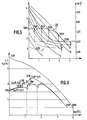
- the pressure-flow regulation curve 29 obtained with a regulation device according to the invention of the type shown diagrammatically in FIG. 2 is indicated in FIG. 5, that is to say a device where the supply voltage of the two phases of the single-phase asynchronous motor (auxiliary phase with capacitor and main phase) is regulated according to the cos ⁇ of the main phase.
- a cos ⁇ of at least 0.79 that is to say that the duration t c of the pulses passing at 15 kHz (see FIG. 4a) decreases as soon as the instantaneous cos ⁇ of the phase principal is less than 0.79 and increases when it is greater than this value of 0.79.
- the more sophisticated regulation curve shown in Figure 6 allows the operation of a pump unit in optimized conditions, i.e. lower noise and lower consumption, especially for the weak pump flow rates.
- the pressure-flow curve shown on the right of figure 6 corresponds to the operation of the engine at full network voltage, i.e. at voltage nominal 220 V, 50 Hz, for networks in the domestic sector in Europe.
- Running without pump flow (at one maximum rotation speed) generates discharge pressure static of about 3.8 m of water column for a consumption of 70 W, while the maximum discharge rate of the pump (in principle at a speed of rotation slightly lower, due to the torque load), reaches 4 m3 / h for a consumption of 80 W.
- the intensity chopping circuit is used in permanent operation to limit the tension power supply to the motor at around 200 V, which reduces its consumption in the maximum flow area (then limited to about 3.5 m3 / h) at 65 W.
- the operation then continues at increasing voltages up to point S where the discharge pressure is approximately 1.8 m of water column for a discharge flow of approximately 1.8 m3 / h.
- the operating points of the pump group then come to place themselves on the curve high flow rate corresponding to the supply of the two phases of the motor (main and auxiliary) under voltage reduced to 200 V by chopping at a frequency of 15 to 20 kHz which conserves the shape of the sinusoid at 50 Hz within limits allowing a reliable and faithful measurement of cos ⁇ (or of the phase shift angle ⁇ , if applicable).
- control of the regulation circuit whose operation is explained in FIG. 6, can have a full power run control button without automatic regulation, allowing for example give a burst of circulation used to chase bubbles of stagnant air on part of the circuit, after closing of the other parts of the circuit.
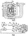
- the dewatering pump group shown in the figures 7 and 8 is in principle intended to be installed in a well collection tank 30 to periodically empty the water it contains.
- a well 30 is for example arranged on the floor of a cellar of building where water infiltration occurs which is to be discharged into the sewer via a discharge line 32.
- the removable dewatering pump 33 is for example included in a plastic body 34 which forms a rotor chamber pump 35 with a ring of collection orifices 36 arranged just above a pump base on the bottom 30a from well 30.
- the pump rotor or impeller 38 cooperates with a passage of suction arranged in a partition 39 of the chamber 35 for define a suction port 40 opening into the chamber lower rotor 35a.
- the pump rotor 38 is connected to a electric drive motor 41 sealingly arranged in an engine chamber 42.
- the tightness of the motor 42 is for example ensured by the fact that motor 41 has a gap tube tightly attached by a frontal flange 43 on a transverse partition 44 of the body pump.
- the partition 44 can be crossed in a non- sealed by the pump rotor shaft without the risk of produce leaks in the engine chamber 42 because the rotor 45 of motor 41 is completely encapsulated in the air gap tube of the motor.
- the wall of the body 34 can be crossed by a connector 47a for inflating the chambers 42, 47 allowing to put these chambers under air or gas pressure neutral dry better preventing possible penetration of water or moisture in these engine and equipment chambers and facilitating the cooling of electrical components or electronic devices liable to heat up.
- a crossing watertight 50 must also be provided, in the cover 49 or the body 34, for the supply wire 51a of the pump, to connect here to the single-phase sector 51.
- the wire feed 51a can be reinforced and placed in the center of the cover 49 to serve as a means of handling and suspension of pump group 33 likely, in some case, to have gone down to the bottom of a deep well.
- the system regulating the pump has two electrodes 52, 53 au contact of the inner wall of insulating material (material plastic) of the sealed chamber 47. These electrodes form thus a level 54 capacitive detector which detects the presence of water in well 30 at least up to the level of the upper electrode 52.
- the pump unit is placed in the collection well 30 in the position shown in Figure 7 while being connected to the 220 V single-phase electrical sector.
- level N of water flowing in the water collection well 30 present or infiltrated on the ground reaches the vicinity of the highest electrode 52 it occurs between the electrodes 52 and 53 a capacitive loop which triggers, by the processing circuit 59, the emission of a signal 56a which energizes operational amplifier 56 and causes emission a signal 64 triggering the closing of the switch 55.
- the electric motor 41 then supplied under the voltage of the single-phase network, starts by indicating, during its phase of start-up, a value of cos ⁇ measured by circuit 63 and which is less than the threshold value 57b.
- the transmission of the output signal 66 of the amplifier 57 is stopped by the timer circuit 65 then excited by the signal starting 64 and the increase in speed of the motor 41 and of the rotor pump 38 continues up to a speed of rotation for which the cos ⁇ measured by circuit 63 becomes greater at threshold value 57b.
- the discharge of the liquid collected in the well 30 is continues through discharge line 32 until the level N of the liquid inside the well 30 reaches the inlet collection orifices 36. There then occurs a increasing air intake at the suction port 40 of the rotor pump 38, which causes the pump to discharge an emulsion decreasing density of liquid and air. Because of the decrease in the effective density of the liquid discharged by the pump, the pump load decreases while the speed of its rotor increases, approaching the synchronism speed and the cos ⁇ of the main phase (winding 60) of the motor 41, as measured by circuit 63, decreases to become below the threshold value 57b.
- Signal 66 delivered by amplifier 57 is then immediately addressed at switch 55 because the delay of circuit 65 is long expired and switch 55 opens cutting the power to motor 41 which continues to run until the pump is primed and the rotor stops pump 38.
- switch 55 opens cutting the power to motor 41 which continues to run until the pump is primed and the rotor stops pump 38.
- the level of liquid N which has risen reaches again electrode 52 a new dewatering cycle resumes as described above.
- the engine asynchronous single phase 41 can be replaced in some more powerful applications by a three-phase asynchronous motor, regulation then taking place in a similar way to that of the diagram of FIG. 1, that is to say with reference to any single phase of the supposedly balanced three-phase motor.
- the motor 41 could even be a collector and ac motor single-phase (universal motor) direct or rectified (motor with ripple current) for which the cos ⁇ or the phase shift angle ⁇ , corresponding to the idle or dewatered running of the pump, is clearly identifiable and constitutes a threshold value suitable for cut off the power supply to the motor.
- the measurement phase shift can however apply to the current alternative supply upstream of the transformer block current (rectifier for ripple current supply or rectifier and inverter for three-phase power with variable frequency of a synchronous motor or a motor asynchronous).
- Regulation of the supply voltage at the terminals of the two phases (main phase, auxiliary phase) of the motor single-phase asynchronous for the embodiments described previously has the advantage of submitting the auxiliary phase capacitor 4 at terminal voltages lower and thereby decrease the risk of breakdown of this capacitor. Such regulation decreases the intensity empty through the auxiliary phase winding 17 and, by consequence, decreases electrical power as much as possible consumed by the single-phase asynchronous motor.
- the minimum or stop voltage can also be determined by the memory card included in the circuit regulation of the supply of the single-phase asynchronous motor.
- the memory card or the regulation circuit of the voltage of the main phase or of the two phases (main and auxiliary) of the engine may also include a member limitation (for example a control circuit for the organ limitation 61b shown in Figure 8) of the intensity going through the main phase of this motor, or the case where applicable, of the total alternating current passing through the motor, so as to constitute a body of protection against short-circuits of the motor, as well as an adjustment device the maximum consumption of the engine.
- a member limitation for example a control circuit for the organ limitation 61b shown in Figure 8 of the intensity going through the main phase of this motor, or the case where applicable, of the total alternating current passing through the motor, so as to constitute a body of protection against short-circuits of the motor, as well as an adjustment device the maximum consumption of the engine.
Landscapes
- Engineering & Computer Science (AREA)
- Power Engineering (AREA)
- Control Of Ac Motors In General (AREA)
- Control Of Positive-Displacement Pumps (AREA)
- Control Of Motors That Do Not Use Commutators (AREA)
- Control Of Eletrric Generators (AREA)
- Control Of Electric Motors In General (AREA)
- Control Of Non-Positive-Displacement Pumps (AREA)
- Dc-Dc Converters (AREA)
Description
- la figure 1 représente schématiquement un dispositif de régulation selon l'invention de l'alimentation du moteur électrique asynchrone triphasé d'un ensemble motogénérateur de pression et/ou de débit de fluide;
- la figure 2 représente schématiquement un dispositif de régulation selon l'invention pour un moteur électrique asynchrone monophasé à phase auxiliaire à condensateur, utilisé pour l'entraínement d'une pompe de circulation d'eau;
- la figure 3 est un schéma électrique et électronique plus détaillé, utilisable pour le dispositif de régulation de la figure 2;
- la figure 4 représente graphiquement: en 4a le mode de découpage d'une alternance du courant électrique monophasé à l'entrée du circuit d'alimentation du moteur électrique contrôlé selon les schémas de régulation des figures 2 et 3, et en 4b la variation sinusoïdale ou quasi-sinusoïdale d'une alternance du courant électrique parcourant la phase principale du moteur électrique monophasé régulé selon les schémas des figures 2 et 3;
- la figure 5 représente graphiquement une courbe d'asservissement pression-débit obtenue par stabilisation du cos ϕ de la phase principale d'un moteur électrique monophasé d'entraínement de pompe dont la tension d'alimentation est régulée selon les schémas des figures 2 et 3;
- la figure 6 représente graphiquement un cycle de régulation automatique pression-débit utilisant des plages successives d'asservissement, à cos ϕ ou à déphasage ϕ constant selon l'invention, pour un groupe motopompe entraíné par un moteur électrique monophasé alimenté sous la fréquence et la tension du réseau, lorsque le circuit de refoulement de la pompe, par exemple un circuit de circulation d'eau de chauffage, est modifié;
- la figure 7 représente schématiquement un groupe de pompe d'exhaure à moteur électrique asynchrone monophasé utilisant le procédé et le dispositif de régulation selon l'invention, à détection de la valeur du cos ϕ ou du déphasage ϕ de la phase principale; et
- la figure 8 représente schématiquement le circuit de régulation marche-arrêt du groupe de pompe d'exhaure de la figure 7.
- coupure de l'aspiration de la pompe ou du ventilateur, ce qui conduit à la dégradation très rapide des paliers de pompe par marche à sec;
- coupure du circuit de refoulement de la pompe ou du ventilateur, ce qui conduit en général au chauffage du circuit de pompe ou de ventilateur et à terme à la dégradation des paliers;
- la réduction à 49 W de la puissance consommée par le moteur et ses circuits de régulation,
- une diminution de la vitesse de rotation du rotor de pompe avec l'augmentation du glissement g par rapport à la vitesse de synchronisme,
- une diminution correspondante de la hauteur de refoulement (limitée à environ 2,1 m de colonne d'eau) et du débit de refoulement (réduit à environ 1,1 m3/h).
- la vitesse de rotation du moteur qui devrait normalement augmenter par suite de la diminution du débit, diminue du fait de l'augmentation du glissement g du rotor par rapport à la vitesse de synchronisme; la hauteur de refoulement statique n'est plus alors que de 1,6 m de colonne d'eau et la marche à vide de la pompe à vitesse réduite est plus silencieuse,
- la consommation de puissance est réduite à 18 W, soit presque le 1/4 de la consommation de 70 W sans débit de refoulement, sous la pleine tension de 220 V. L'échauffement du bloc motopompe en marche sans débit en est réduit d'autant, tandis que la longévité de la pompe est accrue.
- un organe 59 de traitement des indications du détecteur de niveau 54, cet organe 59 fournissant un signal de niveau à une entrée 56a de l'amplificateur 56 dont l'entrée inverse 56b reçoit un signal de consigne de niveau;
- le circuit de phase principale 60 du moteur 41 est équipé d'un capteur d'intensité monophasé de phase principale et d'un capteur 62 de tension de phase principale;
- les signaux des capteurs 61 et 62 sont adressés à un circuit 63 de traitement et de mesure de cos ϕ (ou de phase ϕ) dont le signal de sortie est adressé à l'une des entrées 57a de l'amplificateur 57 dont l'entrée inverse reçoit un signal de consigne de cos ϕ (ou de ϕ). Le circuit d'intensité 61a peut, le cas échéant, traverser un organe de limitation ou disjoncteur 61b assurant une fonction de surveillance électronique de la puissance appelée et des courts-circuits éventuels;
- le signal de sortie 64 de l'amplificateur 56 est adressé à l'interrupteur 55 pour déclencher la fermeture de cet interrupteur et donc l'alimentation du moteur monophasé 41 lorsque les électrodes 52, 53 ont détecté le remplissage du puits 30. Le signal 64 est par ailleurs adressé également à un circuit de temporisation 65 pour l'activer afin de retarder la transmission du signal de sortie 66 de l'amplificateur 57;
- lorsqu'il est transmis à l'interrupteur 55, le signal de sortie 66 de l'amplificateur opérationnel 57 provoque l'ouverture de cet interrupteur 55 et donc la coupure de l'alimentation électrique du moteur 41.
Claims (18)
- Procédé de régulation de l'alimentation d'un moteur électrique asynchrone monophasé du type à phase principale et à phase auxiliaire permanente, dans lequel on mesure l'angle de déphasage du courant par rapport à la tension d'une seule desdites phases et on régule l'alimentation dudit moteur en fonction de la valeur de l'angle de déphasage ainsi mesuré, caractérisé en ce que l'on régule la tension d'alimentation du moteur à l'aide d'un circuit oscillant à découpage ou hachage de la sinusoïde avec reconstitution de la continuité de la sinusoïde d'intensité par un circuit de roue libre, la régulation contrôlant la durée des impulsions de découpage passantes, de manière à disposer d'une mesure fidèle dudit angle de déphasage du courant par rapport à la tension ainsi régulée.
- Procédé selon la revendication 1, caractérisé en ce que la phase auxiliaire est une phase auxiliaire permanente à condensateur et en ce que l'on mesure l'angle de déphasage sur la phase principale dudit moteur.
- Procédé selon la revendication 2, caractérisé en ce que l'on alimente en permanence la phase auxiliaire par la tension du secteur et en ce que l'on régule l'alimentation de la phase principale en fonction de la valeur de l'angle de déphasage mesuré sur la phase principale.
- Procédé selon l'une quelconque des revendications 1 à 3, caractérisé en ce qu'au démarrage du moteur électrique, l'on déclenche une période de temporisation au moins égale à la durée normale de démarrage du moteur et pendant laquelle la régulation de l'alimentation dudit moteur est inhibée.
- Procédé selon l'une quelconque des revendications 1 à 4, caractérisé en ce que l'on régule l'alimentation du moteur de manière à maintenir l'angle de déphasage, dans les limites des possibilités physiques du circuit, à une valeur sensiblement constante.
- Procédé selon l'une quelconque des revendications 1 à 4, caractérisé en ce que l'on régule l'alimentation du moteur de manière à maintenir l'angle de déphasage, dans les limites des possibilités physiques du circuit, à une valeur supérieure à la valeur de seuil.
- Procédé selon l'une quelconque des revendications 1 à 6, caractérisé en ce qu'on régule l'alimentation du moteur de manière à maintenir, dans les limites des possibilités physiques du circuit, une relation déterminée par une carte ou un circuit à mémoire ou relation cartographique entre la tension d'alimentation du moteur et ledit angle de déphasage.
- Procédé selon l'une des revendications 1 à 3, caractérisé en ce que l'on régule en coupant la tension d'alimentation du moteur lorsque l'angle de déphasage mesuré dépasse une valeur de seuil correspondant sensiblement à la marche à vide dudit moteur.
- Application du procédé selon l'une des revendications 1 à 8 au contrôle du moteur électrique d'une pompe par comparaison de l'angle de déphasage mesuré à une valeur de référence spécifique à ladite pompe.
- Application du procédé selon l'une quelconque des revendications 1 à 8 au contrôle du moteur électrique d'entraínement d'une machine rotative à fluide telle qu'une pompe par comparaison de l'angle de déphasage mesuré à une valeur de seuil correspondant à la marche à vide ou dénoyée de la machine et coupure de l'alimentation électrique du moteur lorsque l'angle de déphasage mesuré atteint ladite valeur de seuil.
- Application du procédé selon l'une quelconque des revendications 1 à 8 au contrôle du moteur d'entraínement monophasé d'une machine rotative à fluide telle qu'une pompe par comparaison de l'angle de déphasage mesuré avec une valeur déterminée de seuil ou de consigne correspondant à une valeur minimale régulée de l'angle de déphasage mesuré sur la phase principale dudit moteur monophasé.
- Application du procédé selon la revendication 11, au contrôle du moteur d'entraínement monophasé d'une machine rotative à fluide telle que la valeur déterminée de seuil ou de consigne est donnée par une carte ou un circuit à mémoire en fonction de la tension d'alimentation du moteur.
- Dispositif de régulation de l'alimentation du moteur électrique monophasé asynchrone, à phase auxiliaire permanente à condensateur, d'entraínement d'un générateur rotatif de pression et/ou de débit selon le procédé décrit dans l'une des revendications 1 à 8, caractérisé en ce qu'un moyen de contrôle, interposé entre le réseau du secteur monophasé et ledit moteur, comporte un organe (7) de mesure de l'angle de déphasage du courant par rapport à la tension (ou du cos ϕ) de la seule phase principale du moteur monophasé et un organe (8) de comparaison de la valeur mesurée dudit angle de déphasage avec une valeur de seuil ou de consigne déterminée, et apte à adresser, en cas de dépassement de ladite valeur de seuil ou de consigne, un signal de correction à un régulateur de tension monophasée (23) dont la sortie (UM) alimente ledit moteur électrique monophasé et en ce que ledit régulateur de tension (23) comporte un circuit oscillant à découpage (24, 25), par exemple à semiconducteur piloté par des impulsions de gâchette, apte à produire des impulsions de conduction cadencées et dont la durée (tc) est régulée en fonction de la valeur mesurée de l'angle de déphasage, ainsi qu'un circuit de roue libre (26) assurant la continuité de l'intensité du courant alternatif parcourant les bobinages du moteur, de manière à disposer pour la phase principale (16) d'une mesure stable et fidèle de l'angle de déphasage.
- Dispositif selon la revendication 13, caractérisé en ce que la valeur de seuil ou de consigne déterminée est donnée par une carte ou un circuit à mémoire en fonction de la tension à la sortie du régulateur de tension monophasée (23).
- Dispositif selon la revendication 13, caractérisé en ce qu'il est prévu plusieurs valeurs de seuil ou de consigne prédéterminées et successives du cos ϕ (ou respectivement de l'angle de déphasage ϕ) qui sont de valeurs décroissantes (ou respectivement croissantes pour l'angle ϕ) pour des valeurs de tension décroissantes à la sortie du régulateur de tension monophasée (23) et qui correspondent chacune à une plage de régulation du cos ϕ (ou de l'angle ϕ) entre des valeurs de tension admissibles minimales et maximales à la sortie (UM) du régulateur de tension monophasée.
- Procédé de contrôle de l'alimentation en courant alternatif du moteur électrique d'une pompe ou autre machine à fluide dans lequel on compare la valeur mesurée de l'angle de déphasage du courant par rapport à la tension d'au moins une phase d'alimentation électrique dudit moteur avec une valeur de référence, caractérisé en ce que l'on compare l'angle de déphasage mesuré avec une valeur de seuil correspondant à la marche à vide ou dénoyée de la pompe et l'on coupe l'alimentation électrique du moteur lorsque l'angle de déphasage mesuré atteint ladite valeur de seuil, après une temporisation de démarrage du moteur.
- Dispositif de régulation de l'alimentation du moteur électrique d'un groupe motopompe de vidange automatique du liquide collecté dans une capacité, selon le procédé de la revendication 16, caractérisé en ce qu'un interrupteur marche-arrêt (55) est interposé entre le réseau électrique du secteur (51) et ledit moteur (41), cet interrupteur (55) étant sensible, d'une part, à un signal de démarrage émis à partir d'un détecteur (59) du niveau (N) du liquide dans la capacité (30) et, d'autre part, à un signal d'arrêt émis à partir d'un organe de comparaison (57) entre l'angle de déphasage du courant par rapport à la tension d'au moins une phase d'alimentation dudit moteur électrique et une valeur de seuil correspondant sensiblement à la marche à vide du moteur électrique, le signal de démarrage étant également adressé à un organe (65) de temporisation de la transmission du signal d'arrêt éventuel ou de maintien temporisé de l'alimentation électrique du moteur au démarrage.
- Dispositif selon l'une des revendications 13 à 15 et 17, caractérisé en ce qu'un organe de temporisation (14, 27, 65) dont la durée de temporisation correspond sensiblement à au moins la durée de démarrage du moteur électrique (M, M', 41) est interposé entre la sortie de l'organe de comparaison (8, 56) et l'interrupteur (4, 55) ou le régulateur de tension (23) afin d'inhiber, pendant ladite durée de temporisation, la transmission du signal de sortie de l'organe de comparaison (8, 56) vers l'interrupteur (4, 55) ou le régulateur de tension (23).
Applications Claiming Priority (2)
| Application Number | Priority Date | Filing Date | Title |
|---|---|---|---|
| FR9306839A FR2706228B1 (fr) | 1993-06-08 | 1993-06-08 | Procédé et dispositif de régulation de l'alimentation d'un moteur électrique asynchrone. |
| FR9306839 | 1993-06-08 |
Publications (2)
| Publication Number | Publication Date |
|---|---|
| EP0629037A1 EP0629037A1 (fr) | 1994-12-14 |
| EP0629037B1 true EP0629037B1 (fr) | 2001-08-29 |
Family
ID=9447865
Family Applications (1)
| Application Number | Title | Priority Date | Filing Date |
|---|---|---|---|
| EP94401202A Expired - Lifetime EP0629037B1 (fr) | 1993-06-08 | 1994-05-31 | Procédé et dispositif de régulation de l'alimentation d'un moteur électrique asynchrone |
Country Status (4)
| Country | Link |
|---|---|
| EP (1) | EP0629037B1 (fr) |
| AT (1) | ATE205026T1 (fr) |
| DE (1) | DE69428079T2 (fr) |
| FR (1) | FR2706228B1 (fr) |
Families Citing this family (5)
| Publication number | Priority date | Publication date | Assignee | Title |
|---|---|---|---|---|
| DE19815232A1 (de) * | 1998-04-04 | 1999-10-07 | Grundfos As | Verfahren zur Erfassung eines Parameters eines Asynchronmotors |
| DE60327111D1 (de) * | 2003-10-07 | 2009-05-20 | Askoll Holding Srl | Elektronische Vorrichtung zur Steuerung einer Austragspumpe durch ein Synchronmotor mit Permanentmagnet-Rotor |
| EP2226930B1 (fr) * | 2009-03-06 | 2015-05-13 | Pompes Salmson | Procédé de régulation d'un moteur ayant plusieurs vitesses de fonctionnement |
| UY32914A (es) | 2009-10-02 | 2011-04-29 | Sanofi Aventis | Anticuerpos que se usan específicamente al receptor epha2 |
| CN104653446A (zh) * | 2013-11-22 | 2015-05-27 | 中国航空工业集团公司西安飞机设计研究所 | 一种飞机燃油泵的热保护试验方法 |
Citations (1)
| Publication number | Priority date | Publication date | Assignee | Title |
|---|---|---|---|---|
| EP0311031A2 (fr) * | 1987-10-06 | 1989-04-12 | Grundfos International A/S | Méthode et circuit électrique pour commander un moteur à courant alternatif et pompe de circulation attaquée par un moteur commandé de cette manière |
Family Cites Families (5)
| Publication number | Priority date | Publication date | Assignee | Title |
|---|---|---|---|---|
| US4412167A (en) * | 1980-07-07 | 1983-10-25 | Cynex Manufacturing Corporation | Polyphase power factor controller |
| FR2495855A1 (fr) * | 1980-12-09 | 1982-06-11 | Electro Hydraulique Seh | Moteur electrique asynchrone, dispositif de commande de l'alimentation d'un tel moteur et circulateur comportant un tel moteur |
| DE3120141C2 (de) * | 1981-05-18 | 1983-02-24 | Wolfgang 6200 Wiesbaden Muth | Schaltungsanordnung |
| JPS6188788A (ja) * | 1984-10-05 | 1986-05-07 | Matsushita Electric Ind Co Ltd | 掃除機の位相制御装置 |
| US4806838A (en) * | 1988-05-23 | 1989-02-21 | Weber Harold J | A.C. induction motor energy conserving power control method and apparatus |
-
1993
- 1993-06-08 FR FR9306839A patent/FR2706228B1/fr not_active Expired - Fee Related
-
1994
- 1994-05-31 EP EP94401202A patent/EP0629037B1/fr not_active Expired - Lifetime
- 1994-05-31 DE DE69428079T patent/DE69428079T2/de not_active Expired - Lifetime
- 1994-05-31 AT AT94401202T patent/ATE205026T1/de not_active IP Right Cessation
Patent Citations (1)
| Publication number | Priority date | Publication date | Assignee | Title |
|---|---|---|---|---|
| EP0311031A2 (fr) * | 1987-10-06 | 1989-04-12 | Grundfos International A/S | Méthode et circuit électrique pour commander un moteur à courant alternatif et pompe de circulation attaquée par un moteur commandé de cette manière |
Also Published As
| Publication number | Publication date |
|---|---|
| FR2706228B1 (fr) | 1995-08-11 |
| DE69428079D1 (de) | 2001-10-04 |
| EP0629037A1 (fr) | 1994-12-14 |
| FR2706228A1 (fr) | 1994-12-16 |
| DE69428079T2 (de) | 2002-05-02 |
| ATE205026T1 (de) | 2001-09-15 |
Similar Documents
| Publication | Publication Date | Title |
|---|---|---|
| AU2001269448B2 (en) | Water supply | |
| JP4012604B2 (ja) | 交流電動機のトルクを制御する方法 | |
| FI75030C (fi) | Foerfarande att medelst en borstloes vaexelstroemsmotor driva pumphjulet i en vaetskepump samt vaetskepump foer att utoeva foerfarandet. | |
| CN1068734C (zh) | 基于微处理器的相位差检测电动机控制系统 | |
| FR2793617A3 (fr) | Commande sans capteur de l'angle de puissance pour l'alternateur d'un vehicule | |
| FR2478395A1 (fr) | Alternateur electrique adapte a la puissance de la turbine | |
| FR2965425B1 (fr) | Machine rotative electrique pour une utilisation dans un vehicule | |
| KR20100110260A (ko) | Pwm 신호의 소프트 스타트를 갖는 브러시 없는 dc 모터 | |
| FR2966299A1 (fr) | Machine rotative électrique pour une utilisation dans un véhicule | |
| FR2613150A1 (fr) | Dispositif de commande pour un moteur electrique sous-marin immerge a grande profondeur | |
| EP1269596B1 (fr) | Dispositif d'arret d'un moteur asynchrone monophase a condensateur de dephasage | |
| FR2967312A1 (fr) | Machine electrique rotative de type a enroulement inducteur | |
| EP0629037A1 (fr) | Procédé et dispositif de régulation de l'alimentation d'un moteur électrique asynchrone | |
| US11105323B2 (en) | Motor drive system and method | |
| JP3883382B2 (ja) | 給水装置 | |
| EP0091869B1 (fr) | Ensemble de pompage, tel qu'un circulateur pour installation de chauffage central, à caractéristique hydraulique prédéterminée | |
| JP2002021736A (ja) | 太陽電池を用いた揚水装置 | |
| JP4271958B2 (ja) | 給水装置 | |
| EP0054446B1 (fr) | Moteur électrique asynchrone, dispositif de commande de l'alimentation d'un tel moteur, et circulateur comportant un tel moteur | |
| JP2001123984A (ja) | 水中モータを原動機とする斜流または軸流ポンプの運転制御方法および装置 | |
| FR2824600A1 (fr) | Groupe motopompe dont l'arret s'effectue par analyse du courant | |
| FR3000316A1 (fr) | Systeme de secours pour pompes de turbine | |
| JP4538210B2 (ja) | 水車発電機の自動運転保護装置 | |
| WO2004053505A1 (fr) | Circuit de securite pour ventilateurs de cheminee | |
| JPH09217684A (ja) | 可変速給水装置 |
Legal Events
| Date | Code | Title | Description |
|---|---|---|---|
| PUAI | Public reference made under article 153(3) epc to a published international application that has entered the european phase |
Free format text: ORIGINAL CODE: 0009012 |
|
| AK | Designated contracting states |
Kind code of ref document: A1 Designated state(s): AT BE CH DE DK ES FR GB GR IE IT LI LU NL PT SE |
|
| 17P | Request for examination filed |
Effective date: 19950513 |
|
| 17Q | First examination report despatched |
Effective date: 19970124 |
|
| GRAG | Despatch of communication of intention to grant |
Free format text: ORIGINAL CODE: EPIDOS AGRA |
|
| GRAG | Despatch of communication of intention to grant |
Free format text: ORIGINAL CODE: EPIDOS AGRA |
|
| GRAH | Despatch of communication of intention to grant a patent |
Free format text: ORIGINAL CODE: EPIDOS IGRA |
|
| GRAH | Despatch of communication of intention to grant a patent |
Free format text: ORIGINAL CODE: EPIDOS IGRA |
|
| GRAA | (expected) grant |
Free format text: ORIGINAL CODE: 0009210 |
|
| AK | Designated contracting states |
Kind code of ref document: B1 Designated state(s): AT BE CH DE DK ES FR GB GR IE IT LI LU NL PT SE |
|
| PG25 | Lapsed in a contracting state [announced via postgrant information from national office to epo] |
Ref country code: NL Free format text: LAPSE BECAUSE OF FAILURE TO SUBMIT A TRANSLATION OF THE DESCRIPTION OR TO PAY THE FEE WITHIN THE PRESCRIBED TIME-LIMIT Effective date: 20010829 Ref country code: IE Free format text: LAPSE BECAUSE OF FAILURE TO SUBMIT A TRANSLATION OF THE DESCRIPTION OR TO PAY THE FEE WITHIN THE PRESCRIBED TIME-LIMIT Effective date: 20010829 Ref country code: AT Free format text: LAPSE BECAUSE OF FAILURE TO SUBMIT A TRANSLATION OF THE DESCRIPTION OR TO PAY THE FEE WITHIN THE PRESCRIBED TIME-LIMIT Effective date: 20010829 |
|
| REF | Corresponds to: |
Ref document number: 205026 Country of ref document: AT Date of ref document: 20010915 Kind code of ref document: T |
|
| REG | Reference to a national code |
Ref country code: CH Ref legal event code: EP |
|
| REG | Reference to a national code |
Ref country code: IE Ref legal event code: FG4D Free format text: FRENCH |
|
| REF | Corresponds to: |
Ref document number: 69428079 Country of ref document: DE Date of ref document: 20011004 |
|
| PG25 | Lapsed in a contracting state [announced via postgrant information from national office to epo] |
Ref country code: SE Free format text: LAPSE BECAUSE OF FAILURE TO SUBMIT A TRANSLATION OF THE DESCRIPTION OR TO PAY THE FEE WITHIN THE PRESCRIBED TIME-LIMIT Effective date: 20011129 Ref country code: PT Free format text: LAPSE BECAUSE OF FAILURE TO SUBMIT A TRANSLATION OF THE DESCRIPTION OR TO PAY THE FEE WITHIN THE PRESCRIBED TIME-LIMIT Effective date: 20011129 Ref country code: DK Free format text: LAPSE BECAUSE OF FAILURE TO SUBMIT A TRANSLATION OF THE DESCRIPTION OR TO PAY THE FEE WITHIN THE PRESCRIBED TIME-LIMIT Effective date: 20011129 |
|
| PG25 | Lapsed in a contracting state [announced via postgrant information from national office to epo] |
Ref country code: GR Free format text: LAPSE BECAUSE OF FAILURE TO SUBMIT A TRANSLATION OF THE DESCRIPTION OR TO PAY THE FEE WITHIN THE PRESCRIBED TIME-LIMIT Effective date: 20011130 |
|
| GBT | Gb: translation of ep patent filed (gb section 77(6)(a)/1977) |
Effective date: 20011117 |
|
| REG | Reference to a national code |
Ref country code: GB Ref legal event code: IF02 |
|
| NLV1 | Nl: lapsed or annulled due to failure to fulfill the requirements of art. 29p and 29m of the patents act | ||
| PG25 | Lapsed in a contracting state [announced via postgrant information from national office to epo] |
Ref country code: ES Free format text: LAPSE BECAUSE OF FAILURE TO SUBMIT A TRANSLATION OF THE DESCRIPTION OR TO PAY THE FEE WITHIN THE PRESCRIBED TIME-LIMIT Effective date: 20020228 |
|
| REG | Reference to a national code |
Ref country code: IE Ref legal event code: FD4D |
|
| PG25 | Lapsed in a contracting state [announced via postgrant information from national office to epo] |
Ref country code: LU Free format text: LAPSE BECAUSE OF NON-PAYMENT OF DUE FEES Effective date: 20020531 Ref country code: LI Free format text: LAPSE BECAUSE OF NON-PAYMENT OF DUE FEES Effective date: 20020531 Ref country code: CH Free format text: LAPSE BECAUSE OF NON-PAYMENT OF DUE FEES Effective date: 20020531 Ref country code: BE Free format text: LAPSE BECAUSE OF NON-PAYMENT OF DUE FEES Effective date: 20020531 |
|
| PLBE | No opposition filed within time limit |
Free format text: ORIGINAL CODE: 0009261 |
|
| STAA | Information on the status of an ep patent application or granted ep patent |
Free format text: STATUS: NO OPPOSITION FILED WITHIN TIME LIMIT |
|
| 26N | No opposition filed | ||
| REG | Reference to a national code |
Ref country code: CH Ref legal event code: PL |
|
| PGFP | Annual fee paid to national office [announced via postgrant information from national office to epo] |
Ref country code: GB Payment date: 20130531 Year of fee payment: 20 Ref country code: DE Payment date: 20130531 Year of fee payment: 20 |
|
| PGFP | Annual fee paid to national office [announced via postgrant information from national office to epo] |
Ref country code: FR Payment date: 20130606 Year of fee payment: 20 Ref country code: IT Payment date: 20130531 Year of fee payment: 20 |
|
| REG | Reference to a national code |
Ref country code: DE Ref legal event code: R071 Ref document number: 69428079 Country of ref document: DE |
|
| REG | Reference to a national code |
Ref country code: GB Ref legal event code: PE20 Expiry date: 20140530 |
|
| PG25 | Lapsed in a contracting state [announced via postgrant information from national office to epo] |
Ref country code: GB Free format text: LAPSE BECAUSE OF EXPIRATION OF PROTECTION Effective date: 20140530 |
|
| PG25 | Lapsed in a contracting state [announced via postgrant information from national office to epo] |
Ref country code: DE Free format text: LAPSE BECAUSE OF EXPIRATION OF PROTECTION Effective date: 20140603 |