EP0628762A1 - Hand tool drive - Google Patents
Hand tool drive Download PDFInfo
- Publication number
- EP0628762A1 EP0628762A1 EP94108915A EP94108915A EP0628762A1 EP 0628762 A1 EP0628762 A1 EP 0628762A1 EP 94108915 A EP94108915 A EP 94108915A EP 94108915 A EP94108915 A EP 94108915A EP 0628762 A1 EP0628762 A1 EP 0628762A1
- Authority
- EP
- European Patent Office
- Prior art keywords
- hand tool
- drive
- tool according
- handles
- control logic
- Prior art date
- Legal status (The legal status is an assumption and is not a legal conclusion. Google has not performed a legal analysis and makes no representation as to the accuracy of the status listed.)
- Withdrawn
Links
Images

Classifications
-
- F—MECHANICAL ENGINEERING; LIGHTING; HEATING; WEAPONS; BLASTING
- F16—ENGINEERING ELEMENTS AND UNITS; GENERAL MEASURES FOR PRODUCING AND MAINTAINING EFFECTIVE FUNCTIONING OF MACHINES OR INSTALLATIONS; THERMAL INSULATION IN GENERAL
- F16P—SAFETY DEVICES IN GENERAL; SAFETY DEVICES FOR PRESSES
- F16P3/00—Safety devices acting in conjunction with the control or operation of a machine; Control arrangements requiring the simultaneous use of two or more parts of the body
-
- A—HUMAN NECESSITIES
- A01—AGRICULTURE; FORESTRY; ANIMAL HUSBANDRY; HUNTING; TRAPPING; FISHING
- A01G—HORTICULTURE; CULTIVATION OF VEGETABLES, FLOWERS, RICE, FRUIT, VINES, HOPS OR SEAWEED; FORESTRY; WATERING
- A01G3/00—Cutting implements specially adapted for horticultural purposes; Delimbing standing trees
- A01G3/04—Apparatus for trimming hedges, e.g. hedge shears
- A01G3/047—Apparatus for trimming hedges, e.g. hedge shears portable
- A01G3/053—Apparatus for trimming hedges, e.g. hedge shears portable motor-driven
-
- B—PERFORMING OPERATIONS; TRANSPORTING
- B27—WORKING OR PRESERVING WOOD OR SIMILAR MATERIAL; NAILING OR STAPLING MACHINES IN GENERAL
- B27B—SAWS FOR WOOD OR SIMILAR MATERIAL; COMPONENTS OR ACCESSORIES THEREFOR
- B27B17/00—Chain saws; Equipment therefor
- B27B17/0008—Means for carrying the chain saw, e.g. handles
-
- H—ELECTRICITY
- H01—ELECTRIC ELEMENTS
- H01H—ELECTRIC SWITCHES; RELAYS; SELECTORS; EMERGENCY PROTECTIVE DEVICES
- H01H3/00—Mechanisms for operating contacts
- H01H3/02—Operating parts, i.e. for operating driving mechanism by a mechanical force external to the switch
- H01H3/14—Operating parts, i.e. for operating driving mechanism by a mechanical force external to the switch adapted for operation by a part of the human body other than the hand, e.g. by foot
- H01H3/141—Cushion or mat switches
- H01H3/142—Cushion or mat switches of the elongated strip type
-
- H—ELECTRICITY
- H01—ELECTRIC ELEMENTS
- H01H—ELECTRIC SWITCHES; RELAYS; SELECTORS; EMERGENCY PROTECTIVE DEVICES
- H01H9/00—Details of switching devices, not covered by groups H01H1/00 - H01H7/00
- H01H9/02—Bases, casings, or covers
- H01H9/06—Casing of switch constituted by a handle serving a purpose other than the actuation of the switch, e.g. by the handle of a vacuum cleaner
-
- H—ELECTRICITY
- H01—ELECTRIC ELEMENTS
- H01H—ELECTRIC SWITCHES; RELAYS; SELECTORS; EMERGENCY PROTECTIVE DEVICES
- H01H9/00—Details of switching devices, not covered by groups H01H1/00 - H01H7/00
- H01H9/54—Circuit arrangements not adapted to a particular application of the switching device and for which no provision exists elsewhere
- H01H9/547—Combinations of mechanical switches and static switches, the latter being controlled by the former
Definitions
- the present invention relates to a hand tool with a drive, in particular in the form of a chain saw or hedge trimmer, the hand tool being equipped with two handles and a switching element provided for controlling the drive, and to ensure two-hand operation on each of the two handles has a securing element which interacts with the switching element in such a way that the switching element can only be actuated when both handles are gripped.
- Such a hand tool in the form of a chain saw is e.g. known from DE 87 16 112.5 U1.
- these precautions include, for example, additional control elements integrated into the handles.
- a chainsaw with a first handle integrated into the housing and a handle arranged on the housing is proposed as a further handle, in which in addition to a first control element consisting of a securing element and a switching element for the chain drive, a further control element is provided in the handle in the first handle.
- the chain drive can only be activated if, in addition to the first, the second control link is also operated.
- the second control element is designed as an actuator that is operatively connected to a switch, preferably via a Bowden cable. In one of the switch positions, the switch itself interrupts the mechanical, hydraulic or electrical connection between the first control element and the chain drive.
- the known solution is equipped with complex mechanical devices such as a Bowden cable or the push-button-like securing element in the rear handle, which are prone to failure.
- the electromechanical rockers or switches operated with it still do not offer sufficient operating safety.
- the switching elements used (with an electric drive) are always arranged on the mains voltage side, which leads to insulation and safety problems.
- At least one of the two fuse elements is designed as an electrically effective linear sensor and controls the drive via control logic designed as a low-voltage circuit.
- the essence of the invention is to design the safety circuit on the basis of a linear, electrically operating sensor as an electronic logic circuit in the low-voltage range. On the one hand, this reliably avoids touching dangerous voltages when handling the device. On the other hand, due to its electronic structure, the safety circuit is less prone to failure and easy to use.
- the use of the control logic also enables the use of relatively high-resistance sensors, so that a total of a large number of sensors are available for the safety circuit.
- additional signal generators for example a sensor for the chain brake of a chainsaw, can be switched on within the logic circuit and thus also into the safety circuit be included.
- the sensors can be kept very small since they only have to process low control outputs. This is an important advantage because there is not enough space for circuit breakers in many steps.
- both securing elements are designed as electrically operating, linear sensors and are connected together to the control logic.
- both fuse elements can be connected to the control logic in the same way.
- the linear design of the two sensors ensures that the safety circuit responds reliably even with a different handle position and different hand size and enables smooth operation of the device.
- a second preferred embodiment is characterized in that the hand-held tool has an electric motor that can be operated with mains voltage as a drive, that the control logic can be connected to the mains via a galvanically isolating power pack, and that the control logic controls the electric motor via a motor control unit (e.g. relay).
- a motor control unit e.g. relay
- a third preferred embodiment of the invention is characterized in that the or the linear Sensors each comprise two contact conductors which are arranged parallel to one another in a hose-like, elastic and non-conductive plastic channel and do not touch in the unpressed state of the plastic channel, which come into contact with one another when the plastic channel is pressed together and emit an electrical signal by closing the contact.
- This type of sensor has the advantage that it is robust and protected from the outside and enables reliable contact over a relatively long sensor length.
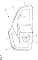
- FIG. 1 shows a preferred embodiment of a hand tool according to the invention.
- the hand-held tool 100 has a housing 10 for receiving a drive 14, which can be designed, for example, as an internal combustion engine or electric motor and can be seen in the figure by the fan blade indicated.
- a rear handle 11 Integrated in the housing 10 is a rear handle 11, which is usually gripped with the right hand in the embodiment shown.
- a button-shaped switching element 13 Arranged within the rear handle 11 is a button-shaped switching element 13, which is actuated with a finger of the right handle hand and by means of which the drive 14 can basically be switched on in the manner of a main switch.
- a first fuse element 15 in the form of a linear sensor.
- the securing member 15 protrudes along its axis with a part from the handle body and is forced in when the handle 11 is gripped by the handle hand. Due to the internal structure of the sensor, which will be explained in more detail later, an electrical contact is closed in the sensor by being pressed in and is evaluated as a safety signal by the safety electronics, not shown here.
- a further handle 12 in the form of a handle is arranged in front of the housing, which must be gripped by the left hand in two-hand operation.
- a second securing element 16 is embedded on the outside, which is constructed as a linear sensor in the same way as the first securing element 15.
- the arrangement of the two securing elements 15 and 16 ensures that, with suitable interaction with the switching element, that the handheld device 100 can only be put into operation as intended if the two handles 11, 12 are gripped by one hand at a time.
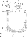
- the arrangement and internal structure of the securing member 16 in the handle of the handle 12 can be explained in more detail with reference to FIG. 2.
- FIG. 2a shows a longitudinal section of the handle 12 from FIG. 1.
- the handle can be made of solid material or a with plastic-filled metal pipe or the like. be made.
- a groove 17 is embedded over the largest part of the encompassable length, which - as the cross section along the area AA in FIG. 2b shows - accommodates the sensor-like securing element 16.
- the linear sensor preferably consists of a hose-like plastic channel 22 made of a non-conductive elastomer, in the cavity 18 of which two electrical contact conductors 19a, b are located opposite one another and not touching, parallel to one another run.
- the contact conductors 19a, b can consist, for example, of an electrically conductive elastomer or of a metal or other conductive layer applied to the surface.
- the two contact conductors 19a, b come into contact with one another, so that the sensor line which can be connected to the logic by corresponding connections is closed and a signal is generated which is fed as a control signal to the logic circuit.
- a film-like strip instead of the tube-like channel, which strip also closes a contact when pressure is applied, stretched or bent, or changes a resistance in such a way that a switching signal is generated.
- a closed elastic hose to be used, the volume of which is connected to an electrical pressure sensor.
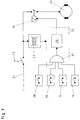
- the fuse elements 15 and 16 from FIG. 1 are connected to a fuse and logic circuit, the basic structure of which is shown in FIG. 3 in the case of a manual power tool that is electrically powered from the network:
- the drive comprises an electric motor 25 which can be connected to a power line 21 via a central motor control unit 24 (for example a relay) (and the switching element 13 designed as a button).
- the ditto 24 is controlled by a control logic 20, which is supplied from the network via a galvanically isolated power supply unit 23 and essentially contains an AND gate 27 at the input and a power unit 26 at the output.
- the power section 26 is designed, for example, as a circuit breaker and controls the current through the motor control unit 24.
- the AND gate 27 has a large number of inputs, as required, via which switching and fuse signals from various switching and fuse elements can be logically linked , so that the same 24 works only when all inputs of the AND gate 27 simultaneously assume the same logical state (1 or 0).
- Additional signal transmitters can be an overload switch 28 and - in the case of a chainsaw be in contact with the chain brake.
- the overload switch 28 can be designed, for example, as a thermal switch which protects the electric motor 25 against thermal overload.
- the contact 29 of the chain brake is closed when the chain brake is released.
- FIG. 4 A circuit structure of a circuit according to FIG. 3 which has been tried and tested in practice is shown in FIG. 4:
- the securing members 15 and 16 are designed in the form described above as hose resistors which, depending on the location of the actuation, have a resistance R2 or R3 between a few 100 to approximately 600 ohms at a maximum total hose length of 300 mm, for example.
- Via the switching element 13, a circuit breaker, the power supply of the electric saw (or the like) is switched on.
- the transformer 30 transforms the mains voltage when the transformer is loaded from the mains voltage to a low-voltage value that can be used for the electronic components.
- a bridge rectifier 31 converts the step-down AC voltage into a pulsating DC voltage.
- the two fuse elements 15 and 16 and possibly further switching elements 28, 29 are in series with a series resistor R1 and, together with a further resistor, form a voltage divider to which a transistor 33 is connected with its base.
- a transistor base current flows so that the transistor 33 in the collector-emitter path becomes conductive and a collector current can flow, whereby a motor relay 24 picks up and closes the load circuit and sets the electric motor in motion.
- the switching contacts 15, 16, 28 and 29 connected in series embody an elementary form of the AND gate in the circuit from FIG.
- the transistor 33 represents a power section which controls the motor relay 24.
- the simple circuit structure with proven components results in a robust and safely functioning circuit that can easily be extended to other signal contacts.
- suitable integrated circuits can also be used instead of the discrete components.
- the invention results in an externally powered hand-held device with a safety circuit, which is simple in construction, easy and safe to use and can be flexibly adapted to different applications.
Abstract
Description
Die Vorliegende Erfindung betrifft ein Handarbeitsgerät mit einem Antrieb, insbesondere in Form einer Kettensäge oder Heckenschere, wobei das Handarbeitsgerät mit zwei Handgriffen und einem für die Steuerung des Antriebs Vorgesehenen Schaltglied ausgestattet ist, und zur Sicherstellung einer Zwei-Hand-Bedienung an jedem der zwei Handgriffe ein Sicherungsglied aufweist, welches mit dem Schaltglied derart zusammenwirkt, daß eine Betätigung des Schaltgliedes nur beim Umfassen beider Handgriffe erfolgen kann.The present invention relates to a hand tool with a drive, in particular in the form of a chain saw or hedge trimmer, the hand tool being equipped with two handles and a switching element provided for controlling the drive, and to ensure two-hand operation on each of the two handles has a securing element which interacts with the switching element in such a way that the switching element can only be actuated when both handles are gripped.
Ein solches Handarbeitsgerät in Form einer Kettensage ist z.B. aus der DE 87 16 112.5 U1 bekannt.Such a hand tool in the form of a chain saw is e.g. known from DE 87 16 112.5 U1.
Bei fremdangetriebenen, d.h. mit einem Elektro- oder Verbrennungsmotor oder einem hydraulischen oder pneumatischen Antrieb ausgestatteten Handarbeitsgeräten ist es häufig aus Sicherheitsgründen notwendig, Vorkehrungen zu treffen, die gewährleisten, daß das jeweilige Gerät während des Einsatzes mit beiden Händen an dafür Vorgesehenen Griffen gehalten wird (Zwei-Hand-Bedienung). Diese Vorkehrungen umfassen beispielsweise neben dem Hauptsteuerschalter zusätzliche, in die Griffe integrierte Steuerglieder.For externally driven, i.e. For safety reasons, it is often necessary to take precautions to ensure that the respective device is held with both hands on the handles provided for this purpose (two-hand operation) with an electric or internal combustion engine or a hydraulic or pneumatic drive ). In addition to the main control switch, these precautions include, for example, additional control elements integrated into the handles.
So wird in der DE 87 16 112 U1 eine Kettensäge mit einer ersten, in das Gehäuse integrierten Handhabe und einem am Gehäuse angeordneten Griffbügel als weiterer Handhabe vorgeschlagen, bei dem neben einem ersten, aus einem Sicherungsglied und einem Schaltglied bestehenden ersten Steuerglied für den Kettenantrieb in der ersten Handhabe ein weiteres Steuerglied im Griffbügel vorgesehen ist. Der Kettenantrieb ist nur ansteuerbar, wenn neben dem ersten auch das zweite Steuerglied betätigt wird.In DE 87 16 112 U1, a chainsaw with a first handle integrated into the housing and a handle arranged on the housing is proposed as a further handle, in which in addition to a first control element consisting of a securing element and a switching element for the chain drive, a further control element is provided in the handle in the first handle. The chain drive can only be activated if, in addition to the first, the second control link is also operated.
Das zweite Steuerglied ist dabei als mit einem Schalter vorzugsweise über einen Bowdenzug in Wirkverbindung stehendes Betätigungsglied ausgebildet. Der Schalter selbst unterbricht in einer der Schalterstellungen die mechanische, hydraulische oder elektrische Verbindung zwischen dem ersten Steuerglied und dem Kettenantrieb.The second control element is designed as an actuator that is operatively connected to a switch, preferably via a Bowden cable. In one of the switch positions, the switch itself interrupts the mechanical, hydraulic or electrical connection between the first control element and the chain drive.
Die bekannte Lösung ist mit aufwendigen mechanischen Einrichtungen wie z.B. einem Bowdenzug oder dem druckknopfartigen Sicherungsglied im hinteren Handgriff ausgerüstet, die störungsanfällig sind. Die damit betätigten elektromechanischen Wippen oder Schalter bieten weiterhin keine ausreichende Bedienungssicherheit. Darüber hinaus sind die verwendeten Schaltelemente (bei elektrischem Antrieb) grundsätzlich auf der Netzspannungsseite angeordnet, was zu Isolations- und Sicherheitsproblemen führt. Schließlich ist es beim bekannten System nur schwer möglich, weitere Sicherheitseinrichtungen und deren Signale auszuwerten und bei der Sicherheitsschaltung zu berücksichtigen.The known solution is equipped with complex mechanical devices such as a Bowden cable or the push-button-like securing element in the rear handle, which are prone to failure. The electromechanical rockers or switches operated with it still do not offer sufficient operating safety. In addition, the switching elements used (with an electric drive) are always arranged on the mains voltage side, which leads to insulation and safety problems. Finally, in the known system it is difficult to evaluate further safety devices and their signals and to take them into account in the safety circuit.
Es ist daher Aufgabe der Erfindung, ein fremdangetriebenes Handarbeitsgerät zu schaffen, dessen Sicherheitsschaltung für die Zwei-Hand-Bedienung störunanfällig, leicht und gefahrlos zu bedienen und flexibel an verschiedene Gegebenheiten anzupassen ist.It is therefore an object of the invention to provide an externally powered hand tool, the safety circuit for two-hand operation is trouble-free, easy and safe to use and can be flexibly adapted to different circumstances.
Die Aufgabe wird durch die im Patentanspruch 1 gekennzeichneten Merkmale gelöst.The object is achieved by the features characterized in claim 1.
Es ist dabei bei einem Gerät der eingangs genannten Art vorgesehen, daß zumindest eines der beiden Sicherungsglieder als elektrisch wirksamer linienförmiger Sensor ausgebildet ist und über eine als Niederspannungsschaltung ausgelegte Steuerlogik den Antrieb steuert.In a device of the type mentioned at the outset, it is provided that at least one of the two fuse elements is designed as an electrically effective linear sensor and controls the drive via control logic designed as a low-voltage circuit.
Der Kern der Erfindung besteht darin, die Sicherheitsschaltung auf der Grundlage eines linienförmigen, elektrisch arbeitenden Sensors als elektronische Logikschaltung im Kleinspannungsbereich auszuführen. Hierdurch wird einerseits eine Berührung gefährlicher Spannungen beim Handhaben des Gerätes sicher vermieden. Andererseits ist die Sicherheitsschaltung aufgrund ihres elektronischen Aufbaues wenig störanfällig und leicht zu bedienen. Darüber hinaus ermöglicht der Einsatz der Steuerlogik die Verwendung auch von relativ hochohmigen Sensoren, so daß insgesamt eine Vielzahl Von Sensoren für die Sicherheitsschaltung zur Verfügung steht. Weiter können innerhalb der Logikschaltung zwanglos weitere Signalgeber, zum Beispiel ein Sensor für die Kettenbremse einer Kettensäge, zugeschaltet und damit in die Sicherheitsschaltung mit einbezogen werden. Schließlich können die Sensoren sehr klein gehalten werden, da sie nur geringe Steuerleistungen verarbeiten müssen. Dieses ist ein wichtiger Vorteil, da in vielen Handgriffen nicht genügend Bauraum für Leistungsschalter vorhanden ist.The essence of the invention is to design the safety circuit on the basis of a linear, electrically operating sensor as an electronic logic circuit in the low-voltage range. On the one hand, this reliably avoids touching dangerous voltages when handling the device. On the other hand, due to its electronic structure, the safety circuit is less prone to failure and easy to use. In addition, the use of the control logic also enables the use of relatively high-resistance sensors, so that a total of a large number of sensors are available for the safety circuit. Furthermore, additional signal generators, for example a sensor for the chain brake of a chainsaw, can be switched on within the logic circuit and thus also into the safety circuit be included. Finally, the sensors can be kept very small since they only have to process low control outputs. This is an important advantage because there is not enough space for circuit breakers in many steps.
Gemäß einer ersten bevorzugten Ausführungsform des Handarbeitsgerätes nach der Erfindung sind beide Sicherungsglieder als elektrisch arbeitende, linienförmige Sensoren ausgebildet und gemeinsam an die Steuerlogik angeschlossen. Hierdurch können beide Sicherungsglieder in derselben Weise an die Steuerlogik angeschlossen werden. Die linienhafte Ausführung der beiden Sensoren gewährleistet, daß die Sicherheitsschaltung auch bei abweichender Griffhaltung und unterschiedlicher Handgröße sicher anspricht und einen reibungslosen Betrieb des Gerätes ermöglicht.According to a first preferred embodiment of the hand-held tool according to the invention, both securing elements are designed as electrically operating, linear sensors and are connected together to the control logic. As a result, both fuse elements can be connected to the control logic in the same way. The linear design of the two sensors ensures that the safety circuit responds reliably even with a different handle position and different hand size and enables smooth operation of the device.
Eine zweite bevorzugte Ausführungsform zeichnet sich dadurch aus, daß das Handarbeitsgerät als Antrieb einen mit Netzspannung betreibbaren Elektromotor aufweist, daß die Steuerlogik über ein galvanisch trennendes Netzteil an das Netz anschließbar ist, und daß die Steuerlogik den Elektromotor über eine Motoransteuerungseinheit (z.B. Relais) steuert. Diese Auslegung gewährleistet bei einem elektrischen Gerät mit Netzbetrieb die sichere Trennung der Sicherungsglieder von der Netzspannung.A second preferred embodiment is characterized in that the hand-held tool has an electric motor that can be operated with mains voltage as a drive, that the control logic can be connected to the mains via a galvanically isolating power pack, and that the control logic controls the electric motor via a motor control unit (e.g. relay). In the case of an electrical device with mains operation, this design ensures the safe separation of the fuse elements from the mains voltage.
Eine dritte bevorzugte Ausführungsform der Erfindung ist dadurch gekennzeichnet, daß der bzw. die linienförmigen Sensoren jeweils zwei in einem schlauchartigen, elastischen und nichtleitenden Kunststoffkanal parallel zueinander angeordnete, sich im ungedrückten Zustand des Kunststoffkanals nicht berührende Kontaktleiter umfassen, welche beim Zusammendrücken des Kunststoffkanals miteinander in Berührung kommen und durch Schließen des Kontaktes ein elektrisches Signal abgeben. Diese Art von Sensoren hat den Vorteil, daß sie robust und nach außen geschützt ist und einen sicheren Kontakt über eine relativ große Sensorlänge ermöglicht.A third preferred embodiment of the invention is characterized in that the or the linear Sensors each comprise two contact conductors which are arranged parallel to one another in a hose-like, elastic and non-conductive plastic channel and do not touch in the unpressed state of the plastic channel, which come into contact with one another when the plastic channel is pressed together and emit an electrical signal by closing the contact. This type of sensor has the advantage that it is robust and protected from the outside and enables reliable contact over a relatively long sensor length.
Vorteilhafte Ausführungsformen und zweckmäßige Weiterbildungen ergeben sich aus den Unteransprüchen.Advantageous embodiments and expedient further developments result from the subclaims.
Die Erfindung soll nachfolgend anhand von Ausführungsbeispielen im Zusammenhang mit der Zeichnung näher erläutert werden. Es zeigen
- Fig. 1
- in perspektivischer Seitenansicht das Gehäuse mit den beiden Handhaben eines bevorzugten Ausführungsbeispiels der Erfindung mit in beiden Handhaben eingelassenen linienförmigen Sensoren,
- Fig. 2a
- im Längsschnitt den Griffbügel aus Figur 1 mit einer für die Aufnahme des Sensors vorgesehenen Nut (Fig.1a),
- Fig. 2b
- den Querschnitt durch den Griffbügel mit Sensor entlang der Fläche A-A aus Figur 2a,
- Fig. 2c
- im Querschnitt den inneren Aufbau des Sensors aus Fig. 2b,
- Fig. 3
- das Prinzipschaltbild einer beispielhaften Sicherheitsschaltung nach der Erfindung für ein elektrisch angetriebenes Handarbeitsgerät, und
- Fig. 4
- den detailierten Schaltplan einer bewährten Sicherheitsschaltung gem. Fig.3.
- Fig. 1
- a perspective side view of the housing with the two handles of a preferred embodiment of the invention with linear sensors embedded in both handles,
- Fig. 2a
- in longitudinal section the handle from Figure 1 with a groove provided for receiving the sensor (Fig.1a),
- Fig. 2b
- the cross section through the handle with sensor along the surface AA of Figure 2a,
- Fig. 2c
- in cross section the internal structure of the sensor from Fig. 2b,
- Fig. 3
- the basic circuit diagram of an exemplary safety circuit according to the invention for an electrically powered hand tool, and
- Fig. 4
- the detailed circuit diagram of a proven safety circuit acc. Fig. 3.
Figur 1 zeigt ein bevorzugtes Ausführungsbeispiel eines Handarbeitsgerätes nach der Erfindung. Die Figur ist dabei der Einfachheit halber auf den Gehäuseteil mit den Handhaben beschränkt, so daß z.B. Schwert und Kette einer Kettensäge nicht dargestellt sind. Das Handarbeitsgerät 100 weist ein Gehäuse 10 zur Aufnahme eines Antriebes 14 auf, der beispielsweise als Verbrennungsmotor oder Elektromotor ausgebildet sein kann und in der Figur durch den angedeuteten Lüfterflügel zu erkennen ist. In das Gehäuse 10 integriert ist ein hinterer Handgriff 11, der bei der dargestellten Ausführung üblicherweise mit der rechten Hand umgriffen wird. Innerhalb des hinteren Handgriffes 11 ist ein tastenförmiges Schaltglied 13 angeordnet, welches mit einem Finger der rechten Griffhand betätigt und durch welches der Antrieb 14 nach Art eines Hauptschalters grundsätzlich eingeschaltet werden kann.Figure 1 shows a preferred embodiment of a hand tool according to the invention. For the sake of simplicity, the figure is limited to the housing part with the handles, so that e.g. The sword and chain of a chainsaw are not shown. The hand-held
Auf der Außenseite des Handgriffes 11 ist oberhalb des Schaltgliedes 13 ein erstes Sicherungsglied 15 in Form eines linienförmigen Sensors eingelassen.On the outside of the
Das Sicherungsglied 15 ragt entlang seiner Achse mit einem Teil aus dem Griffkörper heraus und wird beim Umfassen des Griffes 11 durch die Griffhand zwangsweise eingedrückt. Aufgrund des später noch näher zu erläuternden inneren Aufbaues des Sensors wird im Sensor durch das Eindrücken ein elektrischer Kontakt geschlossen, der als Sicherungssignal von der hier nicht dargestellten Sicherheitselektronik ausgewertet wird.The securing
Quer zum hinteren Handgriff 11 ist vor dem Gehäuse ein weiterer Handgriff 12 in Form eines Griffbügels angeordnet, der bei der Zwei-Hand-Bedienung durch die linke Hand umgriffen werden muß. Auch in den zweiten Handgriff 12 ist auf der Außenseite ein zweites Sicherungsglied 16 eingelassen, welches als linienförmiger Sensor in derselben Weise aufgebaut ist, wie das erste Sicherungsglied 15. Die Anordnung der beiden Sicherungsglieder 15 und 16 gewährleistet bei einem geeigneten Zusammenwirken mit dem Schaltglied, daß das Handarbeitsgerät 100 nur dann bestimmungsgemäß in Betrieb genommen werden kann, wenn die beiden Handgriffe 11,12 gleichzeitig von jeweils einer Hand umgriffen werden. Anordnung und innerer Aufbau des Sicherungsgliedes 16 im Griffbügel des Handgriffes 12 können anhand der Figur 2 näher erläutert werden.Transversely to the
Figur 2a zeigt im Längsschnitt den Handgriff 12 aus Figur 1. Der Handgriff kann aus Vollmaterial oder einem mit Kunststoff gefüllten Metallrohr od.dgl. hergestellt sein. Auf seiner Außenseite ist über den größten Teil der umgreifbaren Länge eine Nut 17 eingelassen, welche - wie der Querschnitt entlang der Fläche A-A in Figur 2b zeigt - das sensorartige Sicherungsglied 16 aufnimmt.FIG. 2a shows a longitudinal section of the
Ein beispielhafter innerer Aufbau des Sensors ist in der Querschnittsdarstellung der Figur 2c wiedergegeben: Der linienförmige Sensor besteht bevorzugt aus einem schlauchartigen Kunststoffkanal 22 aus einem nichtleitenden Elastomer, in dessen Hohlraum 18 in einem Abstand gegenüberliegend und sich nicht berührend zwei elektrische Kontaktleiter 19a,b parallel zueinander verlaufen. Die Kontaktleiter 19a,b können beispielsweise als Teil des Kunststoffkanals 22 aus einem elektrisch leitfähigen Elastomer oder aus einer oberflächlich aufgebrachten Metall- oder sonstigen Leitschicht bestehen. Beim Zusammendrücken des elastischen Kunststoffkanals 22 kommen die beiden Kontaktleiter 19a,b miteinander in Berührung, so daß hierdurch die durch entsprechende Anschlüsse an die Logik anschließbare Sensorleitung geschlossen und ein Signal erzeugt wird, das als Steuersignal der Logikschaltung zugeführt wird. Es ist andererseits aber auch denkbar und kann vorteilhaft sein, anstelle des schlauchartigen Kanals einen filmartigen Streifen zu verwenden, der ebenfalls bei Druckbeaufschlagung, Dehnung oder Biegung einen Kontakt schließt oder einen Widerstand derart ändert, daß ein Schaltsignal erzeugt wird. Weiterhin ist es auch möglich, einen geschlossenen elastischen Schlauch zu verwenden, dessen Volumen an einen elektrischen Drucksensor angeschlossen ist.An example of the internal structure of the sensor is shown in the cross-sectional illustration in FIG. 2c: The linear sensor preferably consists of a hose-like
Die Sicherungsglieder 15 und 16 aus Figur 1 sind an eine Sicherungs- und Logikschaltung angeschlossen, deren prinzipieller Aufbau im Falle eines elektrisch aus dem Netz angetriebenen Handarbeitsgerätes in Figur 3 wiedergegeben ist:
Der Antrieb umfaßt einen Elektromotor 25, der über eine zentrale Motoransteuerungseinheit 24 (beispielsweise ein Relais) (und das als Taster ausgebildete Schaltglied 13) an eine Netzleitung 21 anschließbar ist. Das dito 24 wird von einer Steuerlogik 20 angesteuert, die über ein galvanisch getrenntes Netzteil 23 aus dem Netz versorgt wird und im wesentlichen ein UND-Glied 27 am Eingang und einen Leistungsteil 26 am Ausgang enthält. Das Leistungsteil 26 ist z.B. als Leistungsschalter ausgelegt und steuert den Strom durch die Motoransteue-rungseinheit 24. Das UND-Glied 27 weist je nach Bedarf eine Vielzahl von Eingängen auf, über die Schalt- und Sicherungssignale von verschiedenen Schalt- und Sicherungsgliedern logisch verknüpft werden können, so daß das dito 24 nur dann arbeitet, wenn alle Eingänge des UND-Gliedes 27 gleichzeitig denselben logischen Zustand (1 oder 0) einnehmen.The
The drive comprises an
Zwei Eingänge des UND-Gliedes 27 sind für die bereits beschriebenen beiden linienförmigen Sicherungsglieder 15 und 16 vorgesehen. Weitere Signalgeber können ein Überlastschalter 28 und - bei einer Kettensäge - ein mit der Kettenbremse in Verbindung stehender Kontakt sein. Der Überlastschalter 28 kann z.B. als Thermoschalter ausgebildet sein, der den Elekromotor 25 vor thermischer Überlastung schützt. Der Kontakt 29 der Kettenbremse wird geschlossen, wenn die Kettenbremse gelöst ist.Two inputs of the AND
Ein in der Praxis bewährter Schaltungsaufbau einer Schaltung nach Figur 3 ist in Figur 4 dargestellt:
Die Sicherungsglieder 15 und 16 sind in der oben beschriebenen Form als Schlauchwiderstände ausgeführt, die, je nach Ort der Betätigung, bei einer maximalen Schlauchgesamtlänge von z.B. 300 mm einen Widerstand R2 bzw. R3 zwischen wenigen 100 bis etwa 600 Ohm haben. Über das Schaltglied 13, einen Leistungsschalter, wird die Spannungsversorgung der Elektrosäge (od.dgl.) eingeschaltet. Der Transformator 30 transformiert die Netzspannung bei Trafonennbelastung von Netzspannung auf einen für die elektronischen Bauelemente verwendbaren Klein-Spannungs-Wert. Ein Brückengleichrichter 31 wandelt die heruntertransformierte Wechselspannung in eine pulsierende Gleichspannung um. Die beiden Sicherungsglieder 15 und 16 und ggf. weitere Schaltglieder 28,29 liegen in Serie mit einem Vorwiderstand R1 und bilden zusammen mit einem weiteren Widerstand einen Spannungsteiler, an den ein Transistor 33 mit seiner Basis angeschlossen ist.A circuit structure of a circuit according to FIG. 3 which has been tried and tested in practice is shown in FIG. 4:
The securing
Werden die beiden Sicherungsglieder 15,16 am hinteren Handgriff 11 und am Griffbügel (Handgriff 12) gleichzeitig (und zusammen mit den ggf. vorhandenen weiteren Schaltkontakten 28,29) betätigt, so fließt ein Transistor-Basisstrom, so daß der Transistor 33 in der Kollektor-Emitterstrecke leitend wird und ein Kollektorstrom fließen kann, wodurch ein Motorrelais 24 anzieht, den Laststromkreis schließt und den Elektromotor in Bewegung setzt.The two securing
Die in Serie geschalteten Schaltkontakte 15,16,28 und 29 verkörpern in der Schaltung aus Figur 4 eine elementare Form des UND-Gliedes. Der Transistor 33 stellt einen Leistungsteil dar, welcher das Motorrelais 24 ansteuert. Der einfache Schaltungsaufbau mit bewährten Bauelementen ergibt eine robuste und sicher funktionierende Schaltung, die leicht auf weitere Signalkontakte ausgeweitet werden kann. Selbstverständlich können anstelle der diskreten Bauelemente auch geeignete integrierte Schaltungen verwendet werden.The switching
Insgesamt ergibt sich mit der Erfindung ein fremdangetriebenes Handarbeitsgerät mit Sicherheitsschaltung, welches einfach aufgebaut, leicht und sicher handhabbar und flexibel an verschiedene Anwendungsfälle anpaßbar ist.Overall, the invention results in an externally powered hand-held device with a safety circuit, which is simple in construction, easy and safe to use and can be flexibly adapted to different applications.
- 1010th
- Gehäusecasing
- 11,1211.12
- HandgriffHandle
- 1313
- SchaltgliedSwitching element
- 1414
- Antriebdrive
- 15,1615.16
- SicherungsgliedSafety link
- 1717th
- NutGroove
- 1818th
- Hohlraumcavity
- 19a,b19a, b
- KontaktleiterContact manager
- 2020th
- SteuerlogikControl logic
- 2121
- NetzleitungPower line
- 2222
- KunststoffkanalPlastic channel
- 2323
- Netzteilpower adapter
- 2424th
- Motoransteuerungseinheit (z.B.Relais)Motor control unit (e.g. relay)
- 2525th
- ElektromotorElectric motor
- 2626
- LeistungsteilPower section
- 2727
- UND-GliedAND gate
- 2828
- ÜberlastschalterCircuit breaker
- 2929
- Kontakt (Kettenbremse)Contact (chain brake)
- 3030th
- Transformatortransformer
- 3131
- BrückengleichrichterBridge Rectifiers
- 3333
- Transistortransistor
- 100100
- HandarbeitsgerätHand tool
- R1,..,R4R1, .., R4
- Widerstandresistance
Claims (8)
dadurch gekennzeichnet,
daß zumindest eines der beiden Sicherungsglieder (15,16) als elektrisch wirksamer linienförmiger Sensor ausgebildet ist und über eine als Niederspannungsschaltung ausgelegte Steuerlogik (20) den Antrieb (14) steuert.Hand tool (100) with a drive (14), in particular in the form of a chain saw or hedge trimmer, the hand tool (100) being equipped with two handles (11, 12) and a switching element (13) provided for controlling the drive (14) , and to ensure two-hand operation on each of the two handles (11, 12) has a securing element (15, 16) which interacts with the switching element (13) in such a way that actuation of the switching element (13) only when it is grasped both handles (11, 12) can take place,
characterized,
that at least one of the two fuse elements (15, 16) is designed as an electrically effective linear sensor and controls the drive (14) via a control logic (20) designed as a low-voltage circuit.
dadurch gekennzeichnet,
daß beide Sicherungsglieder (15,16) als elektrisch arbeitende, linienförmige Sensoren ausgebildet und gemeinsam an die Steuerlogik (20) angeschlossen sind.Hand tool according to claim 1,
characterized,
that both safety elements (15, 16) are designed as electrically operating, linear sensors and are connected together to the control logic (20).
dadurch gekennzeichnet,
daß das Handarbeitsgerät (100) als Antrieb (14) einen mit Netzspannung betreibbaren Elektromotor (25) aufweist, daß die Steuerlogik (20) über ein galvanisch trennendes Netzteil (23) an das Netz anschließbar ist, und daß die Steuerlogik (20) den Elektromotor (25) über eine Motoransteuerungseinheit (24), beispielsweise ein Relais, steuert.Hand tool according to claim 2,
characterized,
that the hand-held device (100) has as the drive (14) an electric motor (25) that can be operated with mains voltage, that the control logic (20) has a galvanic separating power pack (23) can be connected to the network, and that the control logic (20) controls the electric motor (25) via a motor control unit (24), for example a relay.
dadurch gekennzeichnet,
daß der bzw. die linienförmigen Sensoren (15,16) jeweils zwei in einem schlauchartigen, elastischen und nichtleitenden Kunststoffkanal (22) parallel zueinander angeordnete, sich im ungedrückten Zustand des Kunststoffkanals (22) nicht berührende Kontaktleiter (19a,b) umfassen, welche beim Zusammendrücken des Kunststoffkanals (22) miteinander in Berührung kommen und durch Schließen des Kontaktes ein elektrisches Signal abgeben.Hand tool according to one of claims 1 to 3,
characterized,
that the line-shaped sensor (s) (15, 16) each comprise two contact conductors (19a, b), which are arranged parallel to one another in a hose-like, elastic and non-conductive plastic channel (22) and do not touch in the unpressed state of the plastic channel (22) Compress the plastic channel (22) into contact with one another and emit an electrical signal by closing the contact.
dadurch gekennzeichnet,
daß der bzw. die linienförmigen Sensoren (15,16) in einer auf der Außenseite des jeweiligen Handgriffes (11,12) angeordneten Nut (17) so untergebracht sind, daß ein zusammendrückbarer Teil der Sensoren (15,16) aus dem Handgriff (11,12) herausragt.Hand tool according to claim 4,
characterized,
that the line-shaped sensor (s) (15, 16) are accommodated in a groove (17) arranged on the outside of the respective handle (11, 12) such that a compressible part of the sensors (15, 16) can be removed from the handle (11 , 12) protrudes.
dadurch gekennzeichnet,
daß die Steuerlogik (20) ein UND-Glied (27) und ein daran angeschlossenes Leistungsteil (26) umfaßt.Hand tool according to one of claims 1 to 5,
characterized,
that the control logic (20) comprises an AND gate (27) and a power section (26) connected to it.
dadurch gekennzeichnet,
daß das UND-Glied (27) als Serienschaltung der Sicherungsglieder (15,16) und ggf. weiterer Schaltkontakte ausgebildet ist, und daß die Leistungsstufe (26) wenigstens einen Transistor (33) umfaßt.Hand tool according to claim 6,
characterized,
that the AND element (27) is designed as a series connection of the fuse elements (15, 16) and possibly further switching contacts, and that the power stage (26) comprises at least one transistor (33).
dadurch gekennzeichnet,
daß die Basis des Transistors (33) an den Mittelabgriff eines Spannungsteilers angeschlossen ist, dessen einer Zweig aus einer Serienschaltung der Sicherungsglieder (15,16), der ggf. weiteren Schaltkontakte und eines Vorwiderstandes (R1), und dessen anderer Zweig aus einem weiteren Widerstand (R4) gebildet wird.Hand tool according to claim 7,
characterized,
that the base of the transistor (33) is connected to the center tap of a voltage divider, the one branch of a series circuit of the fuse elements (15, 16), the possibly further switching contacts and a series resistor (R1), and the other branch of a further resistor (R4) is formed.
Applications Claiming Priority (2)
| Application Number | Priority Date | Filing Date | Title |
|---|---|---|---|
| DE9308698U | 1993-06-11 | ||
| DE19939308698 DE9308698U1 (en) | 1993-06-11 | 1993-06-11 | Hand tool with a drive |
Publications (1)
| Publication Number | Publication Date |
|---|---|
| EP0628762A1 true EP0628762A1 (en) | 1994-12-14 |
Family
ID=6894284
Family Applications (1)
| Application Number | Title | Priority Date | Filing Date |
|---|---|---|---|
| EP94108915A Withdrawn EP0628762A1 (en) | 1993-06-11 | 1994-06-10 | Hand tool drive |
Country Status (3)
| Country | Link |
|---|---|
| EP (1) | EP0628762A1 (en) |
| JP (1) | JPH0747504A (en) |
| DE (1) | DE9308698U1 (en) |
Cited By (9)
| Publication number | Priority date | Publication date | Assignee | Title |
|---|---|---|---|---|
| EP0811315A2 (en) * | 1996-06-05 | 1997-12-10 | GARDENA Kress + Kastner GmbH | Motor-driven hand tool |
| DE19634552A1 (en) * | 1996-08-27 | 1998-03-05 | Metabowerke Kg | Hedge trimmer |
| WO2004073005A1 (en) * | 2003-02-13 | 2004-08-26 | C. & E. Fein Gmbh | Power tool |
| WO2010064937A1 (en) * | 2008-12-04 | 2010-06-10 | Fairbrother Industries Limited | Post driver control |
| WO2012013274A1 (en) * | 2010-07-27 | 2012-02-02 | Wacker Neuson Produktion GmbH & Co. KG | Hand-operated implement with an operator recognition device |
| EP2305439B1 (en) | 2009-10-05 | 2019-12-18 | Makita Corporation | Electric power tool |
| USD887806S1 (en) | 2018-04-03 | 2020-06-23 | Milwaukee Electric Tool Corporation | Jigsaw |
| US10835972B2 (en) | 2018-03-16 | 2020-11-17 | Milwaukee Electric Tool Corporation | Blade clamp for power tool |
| US11014176B2 (en) | 2018-04-03 | 2021-05-25 | Milwaukee Electric Tool Corporation | Jigsaw |
Families Citing this family (8)
| Publication number | Priority date | Publication date | Assignee | Title |
|---|---|---|---|---|
| DE19522970A1 (en) * | 1995-06-28 | 1997-01-02 | Bosch Gmbh Robert | Hedge trimmer |
| DE19617882B4 (en) * | 1996-05-04 | 2005-08-11 | Metabowerke Gmbh | Electromotive hedge trimmer with two-hand operation |
| DE10205951A1 (en) * | 2002-02-13 | 2003-08-21 | Cimosys Ag Goldingen | Control arrangement for mains-dependent devices operated with low-voltage electrical and provided with mains isolation |
| DE102004024035A1 (en) * | 2004-05-11 | 2005-12-08 | Schmid & Wezel Gmbh & Co | Handle for a motor-driven hand tool |
| DE102007043035A1 (en) | 2007-09-11 | 2009-03-12 | Tool Express-Service Schraubertechnik Gmbh | Motorized hand tool used as screwdriver comprises a sensor formed as a proximity switch arranged in the housing of the tool below a handle region |
| EP3031314B1 (en) | 2014-12-09 | 2021-10-13 | Robert Bosch GmbH | Garden device operating device |
| JP6556536B2 (en) * | 2015-07-13 | 2019-08-07 | 株式会社マキタ | Chainsaw |
| DE102018251705A1 (en) * | 2018-12-27 | 2020-07-02 | Robert Bosch Gmbh | Hand tool |
Citations (5)
| Publication number | Priority date | Publication date | Assignee | Title |
|---|---|---|---|---|
| US3662227A (en) * | 1969-02-13 | 1972-05-09 | Cableform Ltd | Control systems |
| EP0048019A2 (en) * | 1980-09-15 | 1982-03-24 | Black & Decker Inc. | Safety arrangement for a powered tool or implement |
| EP0052185A2 (en) * | 1980-11-15 | 1982-05-26 | Robert Bosch Gmbh | Electronic two-hand safety device for tools |
| FR2526126A1 (en) * | 1982-05-03 | 1983-11-04 | Stihl Andreas | SAFETY DEVICE FOR A MOTOR-GUIDED MOTOR APPARATUS |
| EP0544483A1 (en) * | 1991-11-28 | 1993-06-02 | Black & Decker Inc. | Electric tool with gripping sensors |
-
1993
- 1993-06-11 DE DE19939308698 patent/DE9308698U1/en not_active Expired - Lifetime
-
1994
- 1994-06-10 EP EP94108915A patent/EP0628762A1/en not_active Withdrawn
- 1994-06-13 JP JP13023894A patent/JPH0747504A/en active Pending
Patent Citations (5)
| Publication number | Priority date | Publication date | Assignee | Title |
|---|---|---|---|---|
| US3662227A (en) * | 1969-02-13 | 1972-05-09 | Cableform Ltd | Control systems |
| EP0048019A2 (en) * | 1980-09-15 | 1982-03-24 | Black & Decker Inc. | Safety arrangement for a powered tool or implement |
| EP0052185A2 (en) * | 1980-11-15 | 1982-05-26 | Robert Bosch Gmbh | Electronic two-hand safety device for tools |
| FR2526126A1 (en) * | 1982-05-03 | 1983-11-04 | Stihl Andreas | SAFETY DEVICE FOR A MOTOR-GUIDED MOTOR APPARATUS |
| EP0544483A1 (en) * | 1991-11-28 | 1993-06-02 | Black & Decker Inc. | Electric tool with gripping sensors |
Cited By (14)
| Publication number | Priority date | Publication date | Assignee | Title |
|---|---|---|---|---|
| EP0811315A2 (en) * | 1996-06-05 | 1997-12-10 | GARDENA Kress + Kastner GmbH | Motor-driven hand tool |
| DE19622594A1 (en) * | 1996-06-05 | 1997-12-11 | Gardena Kress & Kastner Gmbh | Motorized handheld device |
| EP0811315A3 (en) * | 1996-06-05 | 1998-08-26 | GARDENA Kress + Kastner GmbH | Motor-driven hand tool |
| DE19634552A1 (en) * | 1996-08-27 | 1998-03-05 | Metabowerke Kg | Hedge trimmer |
| WO2004073005A1 (en) * | 2003-02-13 | 2004-08-26 | C. & E. Fein Gmbh | Power tool |
| US7507925B2 (en) | 2003-02-13 | 2009-03-24 | C. & E. Fein Gmbh | Power tool |
| WO2010064937A1 (en) * | 2008-12-04 | 2010-06-10 | Fairbrother Industries Limited | Post driver control |
| AU2009323084B2 (en) * | 2008-12-04 | 2016-07-21 | Fairbrother Industries Limited | Post driver control |
| EP2305439B1 (en) | 2009-10-05 | 2019-12-18 | Makita Corporation | Electric power tool |
| WO2012013274A1 (en) * | 2010-07-27 | 2012-02-02 | Wacker Neuson Produktion GmbH & Co. KG | Hand-operated implement with an operator recognition device |
| US10835972B2 (en) | 2018-03-16 | 2020-11-17 | Milwaukee Electric Tool Corporation | Blade clamp for power tool |
| USD887806S1 (en) | 2018-04-03 | 2020-06-23 | Milwaukee Electric Tool Corporation | Jigsaw |
| US11014176B2 (en) | 2018-04-03 | 2021-05-25 | Milwaukee Electric Tool Corporation | Jigsaw |
| US11813682B2 (en) | 2018-04-03 | 2023-11-14 | Milwaukee Electric Tool Corporation | Jigsaw |
Also Published As
| Publication number | Publication date |
|---|---|
| DE9308698U1 (en) | 1994-10-27 |
| JPH0747504A (en) | 1995-02-21 |
Similar Documents
| Publication | Publication Date | Title |
|---|---|---|
| EP0628762A1 (en) | Hand tool drive | |
| EP1873800B1 (en) | Electrical machine tool and switch therefore | |
| DE3216446C2 (en) | ||
| DE202004002712U1 (en) | Intelligent switch | |
| DE2039862B2 (en) | Automatic aerosol dispenser | |
| EP1496529B1 (en) | Manual operating device for hoisting gears | |
| DE19732888A1 (en) | Operating device for an industrial truck | |
| DE2809747A1 (en) | DOUBLE-POLE SWITCH, ESPECIALLY FOR MOTOR OPERATED TOOLS SUCH AS ELECTRIC DRILLS | |
| EP1593136B1 (en) | Power tool | |
| DE2824510C2 (en) | Device for controlling the movement of a powered door | |
| WO1996013842A1 (en) | Power switch mutually locking arrangement | |
| EP1081725A2 (en) | On/off-switch- and speed regulation device for an electric power tool | |
| DE2929047B2 (en) | Pressure-sensitive switch with pictogram | |
| EP1595661B1 (en) | Handle with safety device for a motorized handtool | |
| EP1929494B1 (en) | Electrical switching device | |
| DE102019201516A1 (en) | Robot with at least one cover and at least one contact sensor | |
| DE3324545A1 (en) | Electric-motor-driven hand-held apparatus | |
| DE2017422C3 (en) | Automatic safety circuit for monitoring the power switching element of an electrical power consumer | |
| DE19621192A1 (en) | Low voltage switchgear | |
| DE3414211C2 (en) | ||
| DE102009012715A1 (en) | Electric switch | |
| EP0085730B1 (en) | Double-pole push switch with electronic control and regulating device for use in hand-held electric appliances | |
| DE102007031016A1 (en) | Electrical switch for power tool e.g. electrical boring machine, has braking circuit arranged in housing and switched-on for braking of electric motor during resetting of operating unit to initial position | |
| DE3447043A1 (en) | Actuation element, in particular for motor vehicles | |
| EP0828278B1 (en) | Remote control for low voltage circuit breaker |
Legal Events
| Date | Code | Title | Description |
|---|---|---|---|
| PUAI | Public reference made under article 153(3) epc to a published international application that has entered the european phase |
Free format text: ORIGINAL CODE: 0009012 |
|
| AK | Designated contracting states |
Kind code of ref document: A1 Designated state(s): CH DE FR GB IT LI SE |
|
| STAA | Information on the status of an ep patent application or granted ep patent |
Free format text: STATUS: THE APPLICATION IS DEEMED TO BE WITHDRAWN |
|
| 18D | Application deemed to be withdrawn |
Effective date: 19950615 |