EP0811315A2 - Motor-driven hand tool - Google Patents
Motor-driven hand tool Download PDFInfo
- Publication number
- EP0811315A2 EP0811315A2 EP97108980A EP97108980A EP0811315A2 EP 0811315 A2 EP0811315 A2 EP 0811315A2 EP 97108980 A EP97108980 A EP 97108980A EP 97108980 A EP97108980 A EP 97108980A EP 0811315 A2 EP0811315 A2 EP 0811315A2
- Authority
- EP
- European Patent Office
- Prior art keywords
- handle
- trigger
- trigger element
- section
- tool according
- Prior art date
- Legal status (The legal status is an assumption and is not a legal conclusion. Google has not performed a legal analysis and makes no representation as to the accuracy of the status listed.)
- Withdrawn
Links
Images

Classifications
-
- A—HUMAN NECESSITIES
- A01—AGRICULTURE; FORESTRY; ANIMAL HUSBANDRY; HUNTING; TRAPPING; FISHING
- A01G—HORTICULTURE; CULTIVATION OF VEGETABLES, FLOWERS, RICE, FRUIT, VINES, HOPS OR SEAWEED; FORESTRY; WATERING
- A01G3/00—Cutting implements specially adapted for horticultural purposes; Delimbing standing trees
- A01G3/04—Apparatus for trimming hedges, e.g. hedge shears
- A01G3/047—Apparatus for trimming hedges, e.g. hedge shears portable
- A01G3/053—Apparatus for trimming hedges, e.g. hedge shears portable motor-driven
Landscapes
- Life Sciences & Earth Sciences (AREA)
- Biodiversity & Conservation Biology (AREA)
- Ecology (AREA)
- Forests & Forestry (AREA)
- Environmental Sciences (AREA)
- Harvester Elements (AREA)
Abstract
Description
Die Erfindung betrifft ein motorisch betriebenes Handgerät, beispielsweise eine Heckenschere, eine Kettensäge, eine Stichsäge o. dgl., bei welchem das Werkzeug langgestreckt oder schwertförmig über eine Gehäuseseite, wie die Vorderseite, um ein Maß vorsteht, das größer als die Gehäuselänge sein kann. Das Werkzeug arbeitet bzw. schneidet in einer Arbeitsebene, die rechtwinklig zu einer Mittelebene, beispielsweise der Längsmittelebene, des Gerätes und/oder parallel dazu bzw. in dieser Mittelebene liegen kann. Im Gehäuse, das den Antriebskopf bildet, ist ein Antrieb, beispielsweise ein Verbrennungsmotor, ein Elektromotor o. dgl. vorgesehen, welcher über ein Getriebe das langgestreckt frei vorstehende Werkzeug am hinteren Ende antreiben kann.The invention relates to a motor-operated hand-held device, for example a hedge trimmer, a chainsaw, a jigsaw or the like, in which the tool protrudes elongated or sword-shaped over a side of the housing, such as the front, by an amount that can be greater than the length of the housing. The tool works or cuts in a working plane that can be perpendicular to a central plane, for example the longitudinal central plane, of the device and / or parallel to it or in this central plane. In the housing which forms the drive head, a drive, for example an internal combustion engine, an electric motor or the like, is provided which can drive the elongated, freely projecting tool at the rear end via a gear.
Um das Handgerät beim Arbeiten mit einer oder beiden Händen frei tragen sowie führen zu können, sind zweckmäßig ein oder zwei gesonderte Griffe vorgesehen, die jeweils mehrere quer aneinander schließende Griffabschnitte zum Umsetzen der zugehörigen Hand aufweisen können, um die Arbeitsebene in beliebige Ausrichtungen gegenüber dem Benutzer bringen zu können. Unbequeme Gerätehaltungen, wie sogenannte Überkopfarbeiten, bei welchen das Gerät mit nach oben gerichteten Armen über dem Kopf des Benutzers geführt wird, sind dabei ergonomisch besonders problematisch, insbesondere hinsichtlich des sicheren Festhaltens und Führens des Gerätes.In order to be able to carry and guide the handheld device freely when working with one or both hands, one or two separate handles are expediently provided, each of which can have a plurality of gripping sections which transversely adjoin one another for relocating the associated hand, in order to position the working plane in any orientation towards the user to bring. Inconvenient device postures, such as so-called overhead work, in which the device with arms pointing upwards out over the head of the user are ergonomically particularly problematic, especially with regard to the safe holding and guiding the device.
Um Verletzungen durch das laufende Werkzeug zu vermeiden, ist ein einziges oder sind mehrere Auslöseorgane, beispielsweise Drucktasten, vorgesehen, welche zum Start sowie zur Aufrechterhaltung des Werkzeuglaufes betätigt sowie betätigt gehalten werden müssen. Sobald ein Auslöseorgan vom Benutzer freigegeben wird, wird der Lauf des Werkzeuges bzw. des Antriebes sofort unterbrochen, weil das Auslöseorgan von selbst, beispielsweise durch Federkraft, in seine Ausgangs- bzw. Ausschaltlage zurückkehrt. Das Auslöseorgan ist zweckmäßig so angeordnet, daß es mit der den zugehörigen Griff haltenden Hand, beispielsweise mit den Innenseiten der den Griffabschnitt umgreifenden Finger zwanglos betätigt gehalten werden kann.In order to avoid injuries from the running tool, a single or multiple triggering elements, for example push buttons, are provided, which must be actuated and kept actuated to start and to maintain the tool run. As soon as a release member is released by the user, the tool or drive is immediately stopped because the release member returns to its initial or switch-off position automatically, for example by spring force. The release member is expediently arranged so that it can be kept pressed with the hand holding the associated grip, for example with the inside of the fingers encompassing the grip section.
Der Erfindung liegt auch die Aufgabe zugrunde, ein Handgerät zu schaffen, bei welchem Nachteile bekannter Ausbildungen bzw. der beschriebenen Art vermieden sind und das insbesondere bei ergonomisch ungünstigem Gebrauch, wie Überkopfgebrauch, sicher in Betrieb zu halten ist.The invention is also based on the object of providing a hand-held device in which disadvantages of known designs or of the type described are avoided and which can be safely kept in operation, in particular in the case of ergonomically unfavorable use, such as overhead use.
Erfindungsgemäß ist als Auslöseorgan ein Auslöseelement bzw. Auslöseglied vorgesehen, das an einer von der Innenseite des Griffes gesonderten Auslöseseite liegt und insbesondere bei Umgreifen des zugehörigen Griffabschnittes mit dem Daumen bzw. der Daumenkuppe der umgreifenden Hand betätigbar ist. Zur Betätigung ist das Auslöseelement zweckmäßig lediglich nach innen zu drücken. Bevorzugt liegt das Auslöseelement im Bereich eines sich etwa in Längsrichtung des Werkzeuges bzw. etwa parallel zur Arbeitsebene erstreckenden Griffabschnittes, der gegenüber der Arbeitsebene oder dem Werkzeug quer versetzt und näher bei der Oberseite des Gehäuses als das Werkzeug liegen kann, welches seinerseits zweckmäßig unmittelbar benachbart zur davon abgekehrten Unterseite des Gehäuses angeordnet ist. Das Auslöseelement ist vorteilhaft quer zur Längsrichtung dieses Griffabschnittes in diesen hinein in einer Richtung betätigbar, die quer zur Längsrichtung des Werkzeuges bzw. zur Arbeitsebene liegt. Auslöseelemente können seitlich am Griff, nämlich an dessen quer an die Griff-Innenseite anschließenden Seitenflächen und/oder an der von der Innenseite abgekehrten Griff-Außenseite zugänglich oder angeordnet sein, so daß derselbe Griffabschnitt gleichermaßen gut mit der linken oder der rechten Hand umklammert und dabei die Auslösung betätigt werden kann.According to the invention, a trigger element or trigger member is provided as the trigger element, which is located on a trigger side separate from the inside of the handle and can be actuated in particular when gripping the associated handle portion with the thumb or the tip of the thumb of the gripping hand. For actuation, the trigger element is expediently only to be pressed inwards. The trigger element is preferably in the region of a handle section which extends approximately in the longitudinal direction of the tool or approximately parallel to the working plane and which is transverse to the working plane or the tool offset and closer to the top of the housing than the tool, which in turn is advantageously located immediately adjacent to the bottom of the housing facing away from it. The release element can advantageously be actuated transversely to the longitudinal direction of this grip section in a direction that is transverse to the longitudinal direction of the tool or to the working plane. Release elements can be accessible or arranged on the side of the handle, namely on its lateral surfaces that adjoin the inside of the handle and / or on the outside of the handle facing away from the inside, so that the same grip section is equally well gripped with the left or right hand and thereby the release can be actuated.
Zweckmäßig weist der Griff auch an der Innenseite ein Auslöseorgan bzw. Auslöseelement auf, beispielsweise einen pistolenartigen Abzug. Beide Auslöseelemente haben die gleiche Funktion, so daß wahlweise nur eines betätigt werden muß, um das Gerät in Betrieb zu nehmen und zu halten. Das weitere Auslöseelement ist vorteilhaft an einem weiteren Griffabschnitt vorgesehen, welcher quer zu den genannten Längsrichtungen, quer zur Arbeitsebene und/oder hinter dem ersten Griffabschnitt liegt. Der weitere Griffabschnitt kann stumpfwinklig an das hintere Ende des ersten Griffabschnittes anschließen, sich von diesem gegen die Arbeitsebene bzw. Unterseite des Gehäuses erstrecken und mit Abstand von der hinteren Seite des Gehäuses bzw. derjenigen Gehäusewandung liegen, welche den Aufnahmeraum für den Antrieb begrenzt. Die Betätigungsrichtungen der beiden Auslöseelemente liegen dann quer zueinander, da diejenige des weiteren Auslöseelementes von der inneren Griffseite zur davon abgekehrten äußeren Griffseite gerichtet ist.The handle also expediently has a trigger element or trigger element on the inside, for example a pistol-like trigger. Both release elements have the same function, so that optionally only one has to be actuated to put the device into operation and hold it. The further trigger element is advantageously provided on a further grip section, which lies transversely to the longitudinal directions mentioned, transversely to the working plane and / or behind the first grip section. The further grip section can connect at an obtuse angle to the rear end of the first grip section, extend from it towards the working plane or underside of the housing and lie at a distance from the rear side of the housing or the housing wall which limits the receiving space for the drive. The actuation directions of the two trigger elements are then transverse to one another, since that of the further trigger element is directed from the inner handle side to the outer handle side facing away from it.
Der zweite Halte- bzw. Traggriff ist vorteilhaft im Abstand vor dem ersten Griff und/oder hinter dem Werkzeug bzw. der zugehörigen Außenseite des Gehäuses angeordnet und kann einen oder mehrere im Winkel aneinanderschließende Griffabschnitte aufweisen, die alle quer zu den genannten Längsrichtungen liegen können. Ein Griffabschnitt des Traggriffes liegt zweckmäßig quer zur Längsmittelebene des Haltegriffes und ein anderer Griffabschnitt etwa parallel zu dieser Ebene oder unter einem spitzen Winkel dazu. Dieser Griffabschnitt kann zu seinem äußeren Ende gegenüber einer der genannten Längsrichtungen nach vorne geneigt sein.The second holding or carrying handle is advantageously arranged at a distance in front of the first handle and / or behind the tool or the associated outside of the housing and can have one or more handle sections which are angled to one another and which can all lie transversely to the longitudinal directions mentioned. A handle section of the carrying handle is expediently located transversely to the central longitudinal plane of the handle and another handle section approximately parallel to this plane or at an acute angle thereto. This grip section can be inclined forward toward its outer end with respect to one of the named longitudinal directions.
Auch für die den jeweiligen Griffabschnitt des Traggriffes umklammernde Hand ist zweckmäßig ein Auslöseorgan der genannten Art, nämlich ein Auslöseglied vorgesehen, welches in der beschriebenen Weise arbeitet. Nur wenn mit jeder Hand eines der zugehörigen Auslöseorgane betätigt gehalten wird, wird der Lauf des Werkzeuges bzw. des Antriebes nicht unterbrochen. Sind für jede Hand mehrere Auslöseorgane vorgesehen, so genügt jeweils die Betätigung eines einzigen. Um bei jeder Gerätehaltung bequem arbeiten zu können, ist für jeden Griffabschnitt des Traggriffes ein gesondertes Auslöseelement vorgesehen. Jedes Auslöseorgan des jeweiligen Griffes kann auf einen gesonderten elektrischen Schalter wirken, die parallel geschaltet sind, während die Schalter der beiden Griffe in Reihe geschaltet sind. Die Auslöseorgane des jeweiligen Griffes können aber auch auf einen gemeinsamen Schalter wirken und mit diesem über ein Übertragungsorgan, wie einen zweiarmigen Schwenkhebel, einen Seilzug o. dgl. verbunden sein. Eine solche Zugorgan-Führung ist der DE-OS 35 31 059 zu entnehmen, auf die wie auf die europäische Patentanmeldung 06 22 015 zur Einbeziehung ihrer Merkmale und Wirkungen in die vorliegende Erfindung bezug genommen wird.Also for the hand clasping the respective grip section of the carrying handle, a release member of the type mentioned is expediently provided, namely a release member which operates in the manner described. Only if one of the associated triggering elements is kept pressed with each hand, the running of the tool or the drive is not interrupted. If several trigger elements are provided for each hand, the actuation of a single one is sufficient. In order to be able to work comfortably with every device position, a separate trigger element is provided for each handle section of the carrying handle. Each release element of the respective handle can act on a separate electrical switch that is connected in parallel, while the switches of the two handles are connected in series. The release members of the respective handle can also act on a common switch and be connected to it via a transmission member, such as a two-armed swivel lever, a cable or the like. Such a tension member guide can be found in DE-OS 35 31 059, to which reference is made to the present invention, as is the case with European patent application 06 22 015, for incorporating its features and effects.
Diese und weitere Merkmale gehen außer aus den Ansprüchen auch aus der Beschreibung und den Zeichnungen hervor, wobei die einzelnen Merkmale jeweils für sich allein oder zu mehreren in Form von Unterkombinationen bei einer Ausführungsform der Erfindung und auf anderen Gebieten verwirklicht sein und vorteilhafte sowie für sich schutzfähige Ausführungen darstellen können, für die hier Schutz beansprucht wird. Ausführungsbeispiele der Erfindung sind in den Zeichnungen dargestellt und werden im folgenden näher erläutert. In den Zeichnungen zeigen:
- Fig. 1
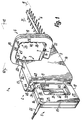
- ein erfindungsgemäßes Handgerät als Heckenschere in vereinfachter perspektivischer Darstellung und
- Fig. 2
- eine weitere Ausführungsform eines Handgerätes in Seitenansicht.
- Fig. 1
- an inventive handheld device as a hedge trimmer in a simplified perspective view and
- Fig. 2
- another embodiment of a handheld device in side view.
Das Gerät 1 weist einen Kopf 2 auf, der im wesentlichen durch ein Gehäuse 3 gebildet ist und ein frei vorstehendes Werkzeug 4, hier ein vielzahniges Schneidwerkzeug mit zwei gegeneinander scherend hin- und herbewegbaren Einzelwerkzeugen trägt, von denen eines mit dem im Gehäuse 3 angeordneten Antrieb oder Motor so gekuppelt ist, daß es in Längsrichtung des Werkzeuges bewegt wird. Das Gerät 1 weist zwei Führungsgriffe, nämlich einen Haltegriff 5 und einen Traggriff 6 auf. Der Griff 5 bildet das hintere Ende des Kopfes 2 und steht als rahmenförmig geschlossener Bügel über die hinterste Außenseite 8 des Gehäuses 3 vor, die seitlich beiderseits über die Seitenflächen des Griffes 5 vorsteht. Mit Abstand davor ist der ebenfalls als geschlossener Rahmen bzw. Bügel ausgebildete Griff 6 angeordnet, der näher bei der vordersten Außenseite 7 des Gehäuses 3 als der Griff 5 liegt und über beide seitlich äußersten Seiten 9 des Gehäuses 3 vorsteht. Der Griff 6 kann gegenüber der Vorderseite 7 bzw. dem hinteren Ende des Werkzeuges 4 zurückversetzt sein, das aus der Vorderseite 7 herausragt.The device 1 has a head 2, which is essentially formed by a housing 3 and carries a freely projecting tool 4, here a multi-tooth cutting tool with two individual tools which can be reciprocated against one another, one of which has the drive arranged in the housing 3 or motor is coupled so that it is moved in the longitudinal direction of the tool. The device 1 has two guide handles, namely a handle 5 and a carrying handle 6. The handle 5 forms the rear end of the head 2 and projects as a frame-shaped closed bracket over the rearmost
Die Einheiten 1 bis 6 sind jeweils symetrisch zu parallelen Ebenen oder einer gemeinsamen Längs-Mittelebene 10 ausgebildet, die hier rechtwinklig zur Arbeitsebene 11 des Werkzeuges 4 liegt. Die Mittelebene des Griffes 9 liegt in der Mittelebene 10 und die Mittelebene 12 des Griffes 6 rechtwinklig quer zur Ebene 10, jedoch unter einem spitzen Winkel von weniger als 45° nach vorne geneigt. Das Werkzeug 4 und die Arbeitsebene 11 liegen näher bei der untersten Außenseite 14 der Einheiten 2, 3, 5, 6 als bei deren obersten Außenseite bzw. der Oberseite 13 des Gehäuses 3 und können unmittelbar benachbart zur Unterseite 14 liegen. Diese Unterseite 14 bildet die unterste Außenseite des Gerätes 1 und eine im wesentlichen ebene, rechtwinklige Standfläche zum sicheren Abstellen des Gerätes 1 auf einer Tragfläche.The units 1 to 6 are each formed symmetrically to parallel planes or to a common longitudinal center plane 10, which here is perpendicular to the working plane 11 of the tool 4. The central plane of the
Der Griff 5 bildet drei gesonderte, im Winkel zueinander liegende Griff-Abschnitte 15 bis 17, die seine Rahmenschenkel bilden und einteilig mit dem Gehäuse 3 ausgebildet sein können. Zweckmäßig bestehen das Gehäuse 3 und der Griff 5 aus zwei jeweils einteiligen Schalenkörpern, die in der Mittelebene 10 gefügt sind und zwischen sich sämtliche Bau- und Funktionsteile des Antriebes sowie der Gerätesteuerung aufnehmen. Jeweils eine Schalenhälfte des Gehäuses 3 ist einteilig mit einer Schalenhälfte des Griffes 5 ausgebildet und bildet eine von deren Seitenflächen, wie die Fläche 9. Das langgestreckte Gerät 1 bestimmt eine Längsrichtung 50, die parallel zur Längsrichtung 51 des Werkzeuges 4 bzw. zu den Ebenen 10, 11 liegt. Die Ebene 12 liegt quer zu den Richtungen 50, 51.The handle 5 forms three separate, mutually
Der am nächsten bei der Oberseite 13 liegende Griff-Abschnitt 16 liegt parallel zu den Richtungen 50, 51 sowie den Ebenen 10, 11 und schließt mit seinem vorderen Ende unmittelbar an die Rückseite 8 an. An das hintere Ende des Abschnittes 16 schließt im rechten Winkel quer das obere Ende des Abschnittes 15 an, der im Abstand hinter der Rückseite 8 und zu dieser parallel liegt. An das untere Ende des Abschnittes 15 schließt im rechten Winkel quer das hintere Ende des Abschnittes 17 an, dessen vorderes Ende wie das des Abschnittes 16 an die Rückseite 8 anschließt. Alle Abschnitte 15 bis 17 liegen in einer gemeinsamen Ebene 10 und sind jeweils so groß, daß jeder Abschnitt für sich mit einer Hand umklammert werden kann. Die untere Außenseite des Abschnittes 17 schließt kontinuierlich an die Unterseite 14 an und bildet einen Teil der Standfläche.The
Der Griff 6 ist durch eine gesonderte, am Gehäuse 3 befestigte Baueinheit gebildet und weist wie der Griff 5 drei im Winkel aneinanderschließende Abschnitte 18 bis 20 auf, so daß auch er gemeinsam mit dem Gehäuse 3 einen geschlossenen Rahmen oder Bügel bildet, welcher mit seinen Rahmen- bzw. Griffabschnitten eine Bügelöffnung über den Umfang durchgehend begrenzt. Der am nächsten bei der Oberseite 13 liegende und über deren zur Unterseite 14 parallele Ebene geringfügig vorstehende Abschnitt 18 liegt rechtwinklig quer zu den Richtungen 50, 51 bzw. zur Ebene 10 und parallel zur Ebene 11, 12 mit geringem Abstand vor demjenigen Bereich der Vorderseite 7, der ihm gegenüberliegt. Dieser Bereich ist gegenüber demjenigen Bereich zurückversetzt, aus welchem das Werkzeug 4 ragt. Die Abschnitte 19, 20 schließen im stumpfen Winkel quer an die Enden des Abschnittes 18 an und erstrecken sich von diesen nach unten in Richtung zum Werkzeug 4 bzw. zur Ebene 11, wobei sie spitzwinklig divergieren, so daß die Abschnitte 18 bis 20 eine abgerundete Trapezform bilden.The handle 6 is formed by a separate unit attached to the housing 3 and, like the handle 5, has three
An die vom Abschnitt 18 entfernten Enden der Abschnitte 19, 20 schließt jeweils im spitzen Winkel quer einwärts gerichtet ein kurzer Schenkel 21 an, mit dessen freiem Ende der Griff 6 an der zugehörigen Seite 9 des Gehäuses 3 starr, jedoch zerstörungsfrei lösbar, befestigt ist. Der Griff 6 kann ebenfalls aus zwei Schalen zusammengesetzt sein, die in der Ebene 12 gefügt sind und die zugehörigen Steuerelemente zwischen sich aufnehmen. Im Übergangsbereich zwischen zwei Griffabschnitten 15, 16 ragt aus der Außenseite des Griffes 5 eine Versorgungsleitung bzw. ein Netz-Anschlußkabel 22 heraus, das zwischen die Schaltenhälften in der Ebene 10 eingesetzt ist.At the ends of the
Zur Steuerung des Gerätes 1 bzw. des Antriebes und des Werkzeuges 4 weist der Griff 5 eine Auslöse-Einheit 23 und der Griff 6 eine Auslöse-Einheit 24 auf. Jede Einheit 23, 24 enthält mehrere, gesonderte sowie gesondert betätigbare Auslöseorgane, die jeweils rechtwinklig quer zum zugehörigen Griffabschnitt bzw. der zugehörigen Abschnittseite zu betätigen sind. Zur Inbetriebnahme sowie Inbetriebhaltung des Antriebes bzw. Werkzeuges 4 muß ein einziges Auslöseorgan jedes Griffes 5, 6 manuell betätigt sowie betätigt gehalten werden. Die Griffabschnitte 15 bis 17 erstrecken sich jeweils in der zugehörigen Längsrichtung 25 bis 27 und die Griffabschnitte 18 bis 20 jeweils in der zugehörigen Längsrichtung 28 bis 30. Die Längsrichtungen 26, 27 der Abschnitte 16, 17 liegen parallel zu den Richtungen 50, 51, während die Längsrichtung 25 des Abschnittes 15 rechtwinklig quer dazu sowie etwa parallel zu den Längsrichtungen 29, 30 der Abschnitte 19, 20 liegt. Die Längsrichtung 28 des Abschnittes 18 liegt quer zu den Richtungen 25 bis 27, 29, 30, 50, 51.To control the device 1 or the drive and the tool 4, the handle 5 has a trigger unit 23 and the handle 6 has a trigger unit 24. Each unit 23, 24 contains a plurality of separate and separately actuatable release elements which are each to be actuated at right angles transversely to the associated handle section or the associated section side. To start up and start up the drive or tool 4, a single release member of each handle 5, 6 must be manually operated and kept operated. The
Jeder Abschnitt 15 bis 17 bildet eine an die Bügelöffnung angrenzende innerste Griffseite 38, an welcher beim Umgreifen außer dem Daumen die Innenseiten aller übrigen Finger der Hand anliegen. Dies gilt auch für die innersten Griffseiten 40 der Abschnitte 18 bis 20. Die Innenseiten 38 sind von der äußersten Seite 39 des jeweils zugehörigen Abschnittes 15 bis 17 abgekehrt und liegen wie diese quer zu den voneinander abgekehrten seitlichen Außenflächen des Griffes 5 bzw. der Abschnitte 15 bis 17. An der Innenseite 38 jedes Abschnittes 15, 17 ist als Auslöseorgan ein Auslöseelement 31, 33 angeordnet, das zur Betätigung in diese Innenseite hineinzudrücken ist.Each
An der Außenseite 39 des Abschnittes 16 ist ein weiteres Auslöseelement 34 vorgesehen, das zur Betätigung in diese Außenseite 39 hineinzudrücken ist. Das Element 34 liegt unmittelbar benachbart zur Rückseite 8 am vorderen Ende des Abschnittes 16 im Bereich einer Fläche 48, die gegenüber dieser Außenseite 39 so vertieft ist, daß die Finger-Druckfläche des Elementes 34 in der Ebene der Außenseite 39 oder demgegenüber geringfügig vertieft liegen kann. Unmittelbar hinter dem Element 34 steigt die Vertiefung 48 zur Fläche 39 an und unmittelbar davor steht die Rückseite 8 nach oben über das Element 34 vor. Dadurch sind unmittelbar vor und hinter dem Element 34 Anschläge 49 für den Daumen gebildet, so daß allein durch Tasten das Element 34 auch dann leicht mit dem Daumen gefunden werden kann, wenn es außerhalb des Sichtbereiches des Benutzers ist. Die Vertiefung 48 geht über die gesamte Breite des Abschnittes 5, 16 durch. Bei Betätigung ist das Element 34 vollständig in der Fläche 48 versenkt. Die Betätigung jedes der Elemente 31, 33, 34 hat die gleiche Wirkung, unabhängig davon, ob eines oder mehrere dieser Auslöseelemente betätigt werden. Die Elemente 31, 33, 34 wirken auf einen gemeinsamen Schalter.On the outside 39 of the
Dies gilt auch für die Auslöseglieder 35 bis 37, die an den Innenseiten 40 der Abschnitte 18 bis 20 angeordnet bzw. zugänglich sind und zur Betätigung in diese Innenseite hineinzudrücken sind. Die Innenseiten der Abschnitte 19, 20 sind einander zugekehrt und die Innenseite des Abschnittes 18 liegt dem Werkzeug 4 gegenüber, wobei sie wie im Falle des Griffes 5 an die Innenseiten der Abschnitte 19, 20 anschließt. Die Glieder 35 bis 37 wirken auf einen gemeinsamen Schalter, der mit dem Schalter der Elemente 31, 33, 34, mit dem Motor und dem Anschlußkabel 22 in Serie geschaltet ist. Die Betätigungsrichtungen 41 bis 43 der Elemente 31 und 33 sind jeweils von der zugehörigen Seite 38 zur davon abgekehrten äußeren Seite 39, d.h. nach außen, gerichtet. Die Betätigungsrichtung 44 des Elementes 34 ist von der zugehörigen äußeren Seite 39 zur davon abgekehrten inneren Seite 38, d.h. nach innen bzw. entgegengesetzt gerichtet. Die beiden Elemente 33, 34 sind nach unten gerichtet zu betätigen, d.h. in jeweils gleicher Richtung. Gegenüber der Betätigungsrichtung 41 des Elementes 31 des Abschnittes 15 liegt die Richtung 44 quer bzw. rechtwinklig.This also applies to the
Die Auslöseglieder 35 bis 37 sind in den Richtungen 45 bis 47 zu betätigen, nämlich von der jeweiligen inneren Seite 40 zur äußeren Seite des zugehörigen Abschnittes 18 bis 20, d.h. nach außen gerichtet parallel zur Ebene 12. Die Elemente 31, 33, 34 und auch das Glied 35 sind parallel zur Ebene 10 zu betätigen. Die Betätigungsrichtung 45 liegt somit quer bzw. in einem von 90° abweichenden Winkel zu den Richtungen 46, 47 der Glieder 36, 37. Alle Richtungen 45 bis 46 weichen von allen Richtungen 41, 43, 44 ab. Die Richtungen 46, 47 liegen jeweils unter einem von 90° abweichendem Winkel zu allen Richtungen 41, 43, 44. Die Richtung 45 ist der Richtung 44 entgegengesetzt und die Richtungen 46, 47 liegen etwa parallel zu den Druckflächen der Elemente 31, 33, 34 sowie wie die Richtung 45 quer zu den Richtungen 50, 51 und zur Ebene 10. Jedes Auslöseelement 31, 33, 34 ist symmetrisch zur Ebene 10 und jedes Auslöseglied 35 bis 37 symmetrisch zur Ebene 12 angeordnet. Unabhängig davon, wie das Gerät zum Arbeiten in Bezug auf den Körper des Benutzers zu halten ist, ist dadurch eine bequeme Betätigung der Einheiten 23, 24 sowie ein sicherer Halt des Gerätes gewährleistet.The
Gemäß Fig. 2 liegen die Abschnitte 15, 16 unter einem stumpfen Winkel zueinander und der entsprechend geneigten Innenseite des Abschnittes 15 sowie dem Element 31 liegt ein etwa paralleler Abschnitt der Rückseite 8 gegenüber. Die Rahmenöffnung des Griffes 5 ist hier stumpfwinklig winkelförmig, wobei ein Winkelschenkel vom Abschnitt 15 und der von diesem nach vorne gerichtete Winkelschenkel vom Abschnitt 16 sowie einer vertieft gegenüberliegenden Oberseite des Gehäuses 3 begrenzt ist. Dadurch kann in jeden Öffnungsschenkel mit der Hand besonders bequem eingegriffen werden. Der Abschnitt 16 ist hier an der Innenseite nicht mit einem Auslöseelement versehen, sondern ein solches Element 31 ist nur an der Innenseite 38 des Abschnittes 15 vorgesehen. Die beiden Abschnitte 15, 16 sind etwa gleich lang und demgegenüber ist der Abschnitt 17 wesentlich kürzer, so daß er hier nicht als Griffabschnitt vorgesehen ist. Die Leitung 22 ragt aus dem Übergang zwischen den Abschnitten 15, 17 parallel zu den Ebenen 10, 11 und zur Richtung 50, 51 heraus. Mit den Elementen 31, 34 ist ein innerhalb des Griffes 5, 15 angeordneter Schalter bzw. Kontakt 53 zu betätigen, dessen Betätigungsrichtung parallel zur Richtung 41 schräg nach hinten und oben gerichtet liegt, so daß sein Betätigungsstößel vom Element 31 in gleicher Richtung 41 mitgenommen werden kann. Das Element 34 betätigt den Schalter 53 über ein Übertragungsglied 54, beispielsweise einen zweiarmigen Schwenkhebel, dessen einer Arm im Abschnitt 16 bewegbar in Eingriff mit dem Element 34 und dessen anderer Arm im Abschnitt 15 bewegbar in Eingriff mit dem Betätigungsstößel des Schalters 53 steht. Das Element 31 wirkt über diesen Arm auf den Betätigungsstößel, da das Ende dieses Armes zwischen dem Element 31 und dem Stößel als Druckkörper angeordnet ist. Der Abschnitt 15 liegt etwa parallel zum Griff 6, so daß die Richtung 41 rechtwinklig quer zur Ebene 12 nach hinten gerichtet ist.2, the
Vor den Griffen 5, 6 und nahe benachbart vor dem Griff 6 ist hinter dem Werkzeug 4 sowie darüber ein Schutzglied 52 vorgesehen, welches beim Abrutschen einer Hand vom Griff 5 bzw. 6 verhindern soll, daß diese Hand in das Werkzeug 4 gerät. Das zur Ebene 12 parallele Schild 52 steht über den zugehörigen Bereich der Ober- bzw. Vorderseite 7 vor, liegt geringfügig hinter demjenigen Abschnitt der Vorderseite 7, aus welchem das Werkzeug 4 herausragt und steht auch seitlich über die Seitenflächen 9 vor.In front of the handles 5, 6 and closely adjacent to the handle 6, a protective member 52 is provided behind the tool 4 and above it, which is intended to prevent a hand from falling into the tool 4 when a hand slips off the handle 5 or 6. The shield 52, which is parallel to the
Alle angegebenen Eigenschaften und Wirkungen können genau wie beschrieben, nur etwa bzw. im wesentlichen wie beschrieben sowie stark davon abweichend vorgesehen sein.All of the properties and effects given can be provided exactly as described, only approximately or essentially as described, and can be very different.
Claims (12)
Applications Claiming Priority (2)
| Application Number | Priority Date | Filing Date | Title |
|---|---|---|---|
| DE1996122594 DE19622594A1 (en) | 1996-06-05 | 1996-06-05 | Motorized handheld device |
| DE19622594 | 1996-06-05 |
Publications (2)
| Publication Number | Publication Date |
|---|---|
| EP0811315A2 true EP0811315A2 (en) | 1997-12-10 |
| EP0811315A3 EP0811315A3 (en) | 1998-08-26 |
Family
ID=7796236
Family Applications (1)
| Application Number | Title | Priority Date | Filing Date |
|---|---|---|---|
| EP97108980A Withdrawn EP0811315A3 (en) | 1996-06-05 | 1997-06-04 | Motor-driven hand tool |
Country Status (2)
| Country | Link |
|---|---|
| EP (1) | EP0811315A3 (en) |
| DE (1) | DE19622594A1 (en) |
Cited By (4)
| Publication number | Priority date | Publication date | Assignee | Title |
|---|---|---|---|---|
| FR2822096A1 (en) * | 2001-03-16 | 2002-09-20 | Stihl Maschf Andreas | PORTABLE WORK TOOL, HAND-HELD AND INCLUDING THUMB SUPPORTS |
| GB2404620A (en) * | 2003-07-14 | 2005-02-09 | Black & Decker Inc | Vegetation pruning device |
| EP1787506A3 (en) * | 2005-11-21 | 2007-07-11 | Husqvarna UK Limited | Power tool |
| EP2196084A3 (en) * | 2008-12-11 | 2010-11-10 | Hitachi Koki CO., LTD. | Hand-held engine-powered tool |
Families Citing this family (1)
| Publication number | Priority date | Publication date | Assignee | Title |
|---|---|---|---|---|
| DE19926375A1 (en) | 1999-06-10 | 2000-12-14 | Gardena Kress & Kastner Gmbh | Motorized garden tools, in particular hedge trimmers |
Citations (3)
| Publication number | Priority date | Publication date | Assignee | Title |
|---|---|---|---|---|
| EP0544483A1 (en) * | 1991-11-28 | 1993-06-02 | Black & Decker Inc. | Electric tool with gripping sensors |
| EP0622015A1 (en) * | 1993-04-08 | 1994-11-02 | GARDENA Kress + Kastner GmbH | Hedge trimmer |
| EP0628762A1 (en) * | 1993-06-11 | 1994-12-14 | Dolmar GmbH | Hand tool drive |
Family Cites Families (12)
| Publication number | Priority date | Publication date | Assignee | Title |
|---|---|---|---|---|
| US3699655A (en) * | 1971-01-18 | 1972-10-24 | Rockwell Mfg Co | Power driven hand tool |
| US4122320A (en) * | 1976-08-16 | 1978-10-24 | Disston, Inc. | Hand-operated double-acting trigger switch |
| DE2651231A1 (en) * | 1976-11-10 | 1978-05-18 | Hugo Freund Fa | Electrically driven hedge shears - has two handles coupled to safety device preventing motor operation unless both are gripped |
| DE2816485C2 (en) * | 1978-04-15 | 1983-09-08 | Reinhold 8531 Hagenbüchach Härtlein | Handle training on a portable power-operated tool, in particular a power saw, hedge trimmer or the like. |
| DE3040516A1 (en) * | 1980-10-28 | 1982-05-27 | Fa. Andreas Stihl, 7050 Waiblingen | SAFETY DEVICE ON A CHAINSAW |
| DE3216446A1 (en) * | 1982-05-03 | 1983-11-03 | Fa. Andreas Stihl, 7050 Waiblingen | SAFETY DEVICE ON A PORTABLE, MOTOR-DRIVEN HAND DEVICE |
| JPS6039479U (en) * | 1983-08-26 | 1985-03-19 | 株式会社 共立 | handle |
| DE3610682C2 (en) * | 1986-03-29 | 1994-01-13 | Bosch Gmbh Robert | Handle for hand machine tools |
| US5150523A (en) * | 1991-07-11 | 1992-09-29 | Ryobi Motor Products Corporation | Deadman switch arrangement for a hedge trimmer |
| US5237752A (en) * | 1992-02-20 | 1993-08-24 | Daryl Maseck | Movable control-handle for chainsaw |
| DE4332986C2 (en) * | 1993-09-28 | 1999-03-11 | Fraunhofer Ges Forschung | Handle for motor-driven tools with adjustable control element |
| GB9323459D0 (en) * | 1993-11-13 | 1994-01-05 | Black & Decker Inc | Improved power tool guard |
-
1996
- 1996-06-05 DE DE1996122594 patent/DE19622594A1/en not_active Withdrawn
-
1997
- 1997-06-04 EP EP97108980A patent/EP0811315A3/en not_active Withdrawn
Patent Citations (3)
| Publication number | Priority date | Publication date | Assignee | Title |
|---|---|---|---|---|
| EP0544483A1 (en) * | 1991-11-28 | 1993-06-02 | Black & Decker Inc. | Electric tool with gripping sensors |
| EP0622015A1 (en) * | 1993-04-08 | 1994-11-02 | GARDENA Kress + Kastner GmbH | Hedge trimmer |
| EP0628762A1 (en) * | 1993-06-11 | 1994-12-14 | Dolmar GmbH | Hand tool drive |
Cited By (6)
| Publication number | Priority date | Publication date | Assignee | Title |
|---|---|---|---|---|
| FR2822096A1 (en) * | 2001-03-16 | 2002-09-20 | Stihl Maschf Andreas | PORTABLE WORK TOOL, HAND-HELD AND INCLUDING THUMB SUPPORTS |
| US7168132B2 (en) | 2001-03-16 | 2007-01-30 | Andreas Stihl Ag & Co. | Portable handheld work apparatus having thumb supports |
| GB2404620A (en) * | 2003-07-14 | 2005-02-09 | Black & Decker Inc | Vegetation pruning device |
| EP1787506A3 (en) * | 2005-11-21 | 2007-07-11 | Husqvarna UK Limited | Power tool |
| EP2196084A3 (en) * | 2008-12-11 | 2010-11-10 | Hitachi Koki CO., LTD. | Hand-held engine-powered tool |
| US8813733B2 (en) | 2008-12-11 | 2014-08-26 | Hitachi Koki Co., Ltd. | Hand-held engine-powered tool |
Also Published As
| Publication number | Publication date |
|---|---|
| EP0811315A3 (en) | 1998-08-26 |
| DE19622594A1 (en) | 1997-12-11 |
Similar Documents
| Publication | Publication Date | Title |
|---|---|---|
| EP2040868B1 (en) | Handheld tool, in particular a handheld saw | |
| EP3792008B1 (en) | Hand-guided appliance with a tool | |
| DE3531059A1 (en) | MOTORIZED HAND DEVICE | |
| DE102010007193B4 (en) | TopHandle portable work machine | |
| DE19905086A1 (en) | Battery operated, hand-held power tool | |
| EP0834248B1 (en) | Motor-driven hedge trimmer | |
| WO1983001406A1 (en) | Tool or tool set | |
| EP2308651B1 (en) | Manually operated machine tool with a hook | |
| DE602004002630T2 (en) | Swivel handle assembly for a power tool | |
| EP0622015B1 (en) | Hedge trimmer | |
| EP2402123B1 (en) | Manually operated machine tool with an energy storage device | |
| EP0811315A2 (en) | Motor-driven hand tool | |
| EP1782682A2 (en) | Manually operated working device | |
| DE602004002438T2 (en) | Locking mechanism for a pivotable handle assembly of a power tool | |
| EP3760025A1 (en) | Operating device with handle and engine-driven working machine | |
| DE602004000897T2 (en) | Actuating mechanism for a power tool | |
| EP2638995B1 (en) | Manual severing machine | |
| DE4332986C2 (en) | Handle for motor-driven tools with adjustable control element | |
| EP2638996B1 (en) | Manual separation machine | |
| EP1059025A2 (en) | Motor-driven garden tool, particularly hedge trimmer | |
| DE602004001941T2 (en) | Handle assembly for a power tool | |
| EP0611634B1 (en) | Multi purpose knife | |
| EP3892082A1 (en) | Handle for a hand-operated tool and free cutter | |
| DE102011006931A1 (en) | Handle for cable wrapping | |
| DE602004002348T2 (en) | Handle assembly for a power tool |
Legal Events
| Date | Code | Title | Description |
|---|---|---|---|
| PUAI | Public reference made under article 153(3) epc to a published international application that has entered the european phase |
Free format text: ORIGINAL CODE: 0009012 |
|
| AK | Designated contracting states |
Kind code of ref document: A2 Designated state(s): AT CH DE FR GB IT LI NL SE |
|
| PUAL | Search report despatched |
Free format text: ORIGINAL CODE: 0009013 |
|
| AK | Designated contracting states |
Kind code of ref document: A3 Designated state(s): AT BE CH DE DK ES FI FR GB GR IE IT LI LU MC NL PT SE |
|
| 17P | Request for examination filed |
Effective date: 19981009 |
|
| AKX | Designation fees paid |
Free format text: AT CH DE FR GB IT LI NL SE |
|
| RBV | Designated contracting states (corrected) |
Designated state(s): AT CH DE FR GB IT LI NL SE |
|
| 17Q | First examination report despatched |
Effective date: 20010523 |
|
| GRAP | Despatch of communication of intention to grant a patent |
Free format text: ORIGINAL CODE: EPIDOSNIGR1 |
|
| STAA | Information on the status of an ep patent application or granted ep patent |
Free format text: STATUS: THE APPLICATION IS DEEMED TO BE WITHDRAWN |
|
| 18D | Application deemed to be withdrawn |
Effective date: 20040331 |