EP0628649A1 - Method for manufacturing a face-to-face pile fabric - Google Patents
Method for manufacturing a face-to-face pile fabric Download PDFInfo
- Publication number
- EP0628649A1 EP0628649A1 EP94201621A EP94201621A EP0628649A1 EP 0628649 A1 EP0628649 A1 EP 0628649A1 EP 94201621 A EP94201621 A EP 94201621A EP 94201621 A EP94201621 A EP 94201621A EP 0628649 A1 EP0628649 A1 EP 0628649A1
- Authority
- EP
- European Patent Office
- Prior art keywords
- pile
- fabric
- threads
- weft
- thread
- Prior art date
- Legal status (The legal status is an assumption and is not a legal conclusion. Google has not performed a legal analysis and makes no representation as to the accuracy of the status listed.)
- Granted
Links
Images


Classifications
-
- D—TEXTILES; PAPER
- D03—WEAVING
- D03D—WOVEN FABRICS; METHODS OF WEAVING; LOOMS
- D03D27/00—Woven pile fabrics
- D03D27/02—Woven pile fabrics wherein the pile is formed by warp or weft
- D03D27/10—Fabrics woven face-to-face, e.g. double velvet
Definitions
- the present invention relates to a method for manufacturing a face-to-face pile fabric, in which
- the pile-forming pile warp threads are in each case interlaced with the third weft threads located on the back of the fabrics (except in case of a change of pile).
- the dead pile warp threads i.e. the pile warp threads or parts of pile warp threads which do not form pile
- a warp thread portee consists of a warp thread system of the top fabric and a warp thread system of the bottom fabric, whose binder warp threads, tension warp threads and pile warp threads are located one above the other).
- each fabric comprises successive rows of pile loops which have been interlaced with corresponding weft threads.
- These pile loops have upright pile sides.
- these pile sides In order to achieve perfect pile formation, these pile sides have to extend at right angles to the plane of the backing fabric (which comprises weft threads, binder warp threads and tension warp threads). If this is not the case (i.e. with a so-called drawn pile), a fabric of inferior quality is obtained. As a result of a drawn pile, mixing contours may occur in the fabrics.
- pile sides form different colour fields in a pile fabric (in order to produce a design or pattern)
- mixing contours occur when pile sides of a different colour are visible among pile sides of one colour on the pile surface of the fabrics. This is caused as a result of pile sides of one colour extending at an angle among the pile sides of another colour in the vicinity of the separation line between two colour fields, and being visible at the pile surface of the fabric.
- the fabric produced according to the method of FR-2.182.790 exhibits a drawn pile.
- first weft threads of successive groups extend in a first plane, which lies on the back relative to a second and third plane in which, respectively, the second and third weft threads of these successive groups extend, because the pile-forming pile warp threads are in each case interlaced with a first weft thread, and because the dead pile warp threads are bound in in each warp thread portee, distributed over both fabrics.
- two weft threads (the second and third weft threads), one above the other, are located in each case on either side of a pile loop. These weft threads keep the pile sides upright. In addition, the first weft thread is prevented from penetrating the second and third weft threads located above one another.
- the pile sides remain in the desired position after the face-to-face pile fabric is cut through, at right angles to the plane of the backing fabric, so that a drawn pile no longer occurs.
- the quality of the fabrics is also improved as the dead pile warp threads are bound in in each warp thread portee distributed over both fabrics.
- the pile warp threads which finish forming pile are interlaced with a second weft thread in a first warp thread portee before they are bound into the top fabric, and the pile warp threads which start forming pile are interlaced with a third weft thread before they start to form pile (run to the bottom fabric).
- the pile warp threads which finish forming pile are interlaced with a third weft thread before they are bound into the bottom fabric, and the pile warp threads which start forming pile are interlaced with a second weft thread before they start forming pile (run to the top fabric).
- the face-to-face pile fabric has alternating first and second warp thread portees.
- the pile sides thus formed are not visible on the back of the fabrics.
- the pattern of the pile fabrics is thus not completely visible on the back of the fabrics. Moreover, the visible part of the pattern appears as a dashed line.
- An additional object of this invention is to produce the complete pattern of the pile fabrics clearly on the back of the fabrics.
- said first and last pile sides are also laterally supported by weft threads located one above the other, after the face-to-face pile fabric has been cut through.
- the pile sides remain upright, thereby preventing mixing contours.
- each pile side is interlaced with a weft thread on the back, so that the pattern is clearly and completely visible on the back of the fabrics.
- Such fabrics are obtained according to the method described in FR-2.182.790.
- each warp thread portee both at a transition from a pile-forming part to a bound-in part and at a transition from a bound-in part to a pile-forming part of a pile warp thread, said pile warp thread is interlaced with a third weft thread before it is bound in or starts forming pile, respectively, and in that the dead pile warp threads in each warp thread portee are bound in distributed over both fabrics.
- the dead pile warp threads are bound in in each warp thread portee distributed over both fabrics. Mixing contours are prevented because all pile sides are supported by adjacent (first) weft threads, so that they remain in the desired upright position after the face-to-face pile fabric has been cut through.
- the first weft thread can also be prevented from penetrating the second and third weft threads lying one above the other by a special way of binding the weft threads in by means of the binder warp threads.
- the groups of weft threads are no longer provided in each case in one opening between the binder warp threads but are distributed in each case over two successive openings, so that a first weft thread or a second weft thread and a third weft thread, respectively, alternately extends between the binder warp threads.
- the dead pile warp threads are bound in distributed over both fabrics in each warp thread portee in order to improve the quality of the fabric.
- the first weft thread is in each case bound into an individual opening, separate from the adjacent second and third weft threads.
- the disadvantageous penetration of the second and third weft threads by the first weft threads is thus prevented.
- the above-mentioned disadvantages which are caused by said penetration are thus overcome by this method according to the invention.
- the penetration of adjacent second and third weft threads by the first weft threads can also be prevented by another special way of binding in the weft threads.
- a complete group of weft threads is also no longer always provided in the successive openings between the binder warp threads.
- the binding in of the weft threads takes place in such a manner that in each case the second and third weft threads extend through said successive openings while the first weft threads extend in each case through an opening which is formed between, on the one hand, two binder warp threads and, on the other hand, the tension warp thread or through an opening which is formed between, on the one hand, the two binder warp threads and, on the other hand, at least one dead pile warp thread.
- first weft threads in each case extend through individual openings and are consequently separated from the adjacent second and third weft threads, they can no longer penetrate said second and third weft threads.
- the abovementioned disadvantages which resulted from said penetration are consequently eliminated.
- the tension warp thread is bound in on the back of the fabric relative to the first weft threads, while the crossing of binder warp threads relative to the first weft threads is provided in each case on the pile side, so that the successive openings are formed between the crossing binder warp threads, on the one hand, and the tension warp thread, on the other.
- the dead pile warp threads are bound in on the pile side of the fabric relative to the first weft threads, while the crossing of the binder warp threads relative to the first weft threads is provided in each case on the back, so that the successive openings are formed between the crossing binder warp threads, on the one hand, and at least one dead pile warp thread, on the other.
- the method as described in the first paragraph of this description can also be carried out in such a manner that the pile-forming pile warp threads are not visible on the back of the fabric (fabrics where pile is not passed through). This is achieved by interlacing the pile-forming pile warp threads in each case with the first weft threads (not located on the back) of successive groups of weft threads.
- the dead pile warp threads are bound in divided over both fabrics and in each warp thread portee so as to improve the quality of the fabrics.
- the third weft threads on the back of the resulting fabrics are not used for interlacing pile threads, such fabrics are suitable in particular for gluing onto surfaces, for example on a floor or walls. Since, in addition, the adhesive is only present between the weft threads on the back and the surface, the flexibility of the fabric pile threads is not affected, yet the adhesion of the fabric on the surface is excellent. The pile thread loops of the active pile do not come into contact with the surface and will therefore not be subject to wear. Moreover, this method requires less pile thread to achieve a certain effective pile height.
- the methods according to this invention where the pile-forming pile warp threads are interlaced with third weft threads in order to produce fabrics where pile passes through can be modified to a method where the pile-forming pile warp threads are interlaced with first weft threads to produce fabrics where pile does not pass through by allowing the interlacing of the pile warp threads to take place one pick earlier or one pick later.
- the first and third weft threads are provided such that they extend in planes lying one above the other, while the tension warp threads are in each case bound in such that they extend between said first and third weft threads.
- the pile-forming pile warp threads are in each case interlaced with the weft thread (the first or third weft thread, depending on the method used according to this invention) running on the back of the tension warp thread, the pattern of the pile fabric is very accurate and clearly visible on the back of the pile fabrics.
- a fabric in particular, a carpet which is weaved according to a three-pick weave tends to curl towards the back. This is caused by the fact that, on the one hand, the pile warp thread bound in on the back prevents the elongation or extension of the fabric on the back, while, on the other hand, the bound-in dead pile warp threads push the fabric apart on the pile side.
- the weft threads situated on the pile side of the dead pile warp threads may push these dead pile warp threads between successive weft threads against the tension warp threads, as a result of which dead pile warp treads are bound in in a wave-like manner and causing increased pile consumption.
- An additional object of this invention is to eliminate these disadvantages.
- This object is achieved in that a second tension warp thread is provided for every warp thread system in each fabric.
- This second tension warp thread is bound in between the second and third weft threads so that only the second weft threads extend on the pile side of this second tension warp thread.
- the first tension warp thread extends between the first and third weft threads of every warp thread system.
- this second tension warp thread the fabric can not extend on the pile side and curling is prevented.
- the weft threads running on the pile side press the dead pile warp threads against the first tension warp threads.
- the dead pile warp threads remain extended and pile consumption for binding in remains at a minimum.
- the warp threads of a warp thread system can be arranged next to one another in the following order: the first tension warp thread, the two binder warp threads, the second tension warp thread, the pile warp threads.
- the pile warp threads are thus in each case situated between two tension warp threads (the second tension warp thread of a warp thread system and the first tension warp thread of a subsequent warp thread system).
- the pile sides are consequently out of range of the binder warp threads, so that these binder warp threads cannot affect the orientation of the pile sides.
- the pile sides assume the desired upright position and form straighter lines in the warp direction on the pile surface. This results in the pile sides not mixing with pile sides of an adjacent row of pile loops.
- an additional tension warp thread may serve as a guide for the weft insertion means so that dead pile warp threads do not have to carry a weft insertion means which could result in them being damaged or breaking as a consequence of their contact with a weft insertion means.
- Double (married) pile warp threads occur when a pile change is effected (when a first pile warp thread which formed pile from a certain pick onwards is bound in and a second pile warp thread which was bound in starts forming pile from the same pick onwards) in the face-to-face fabric, between a first pile warp thread which is to be bound into one fabric after the pile change and a second pile warp thread which was bound into the other fabric before the pile change.
- the pile warp thread whose pile loop is omitted is set so that the omission takes place in the direction where there is more than one pile loop.
- the method according to this invention can be implemented to great effect, using a triple weft insertion mechanism with which, alternately, a second and third weft thread are provided in the bottom fabric and a first weft thread in the top fabric, or a second and third weft thread in the top fabric and a first weft thread in the bottom fabric, respectively.
- At least one weft thread of the two weft threads of each group with which no pile warp thread is interlaced is chosen to be thinner than the other weft threads of that group.
- the pile-forming pile warp threads are thus interlaced in each case with a relatively thick weft thread while one or both of the other weft threads are relatively thin.
- An additional advantage thereof is the fact that the sides of the pile loops are pushed apart to a lesser degree if a relatively thin weft thread extends between these sides. This results in sides which are more upright which again serves to produce a clear and straight delineation of the pile fabric pattern.
- a face-to-face pile fabric is manufactured by forming a top fabric (TF) and a bottom fabric (BF). Both fabrics (TF, BF) are formed by providing for each fabric in each case successive groups of three weft threads (6, 7, 8), so that, in every group, a first weft thread (6) extends next to a second (7) and a third weft thread (8), which are located one above the other, and by providing, for each fabric (TF, BF), adjacent warp thread systems having two binder warp threads (3, 4), one or more tension warp threads (9, 10; 9', 10') and one or more pile warp threads (11-16).
- binder warp threads (3, 4) cross each other a number of times so as to provide successive openings (49-55; 49, 49', 50, 50'; 49, 49'', 501 50''...; 49, 49''', 50, 50'''...) between their points of intersection, through which extend in each case one or more weft threads (6, 7, 8).
- the weft threads (6, 7, 8) are bound into the respective fabrics (TF, BF).
- the tension warp threads (9, 10;, 9', 10') are bound into the respective fabrics (TF, BF) in each of the warp thread systems.
- the pile-forming pile warp threads (11-14) are interlaced with a weft thread (6, 8) alternately in the top fabric (TF) and in the bottom fabric (BF) in accordance with a three-pick weave.
- a dead pile warp thread (11-16) is bound into one of the fabrics (TF, BF).
- a pile warp thread (11-14) may have a part which forms pile and another part which may be bound in as dead pile warp thread.
- the face-to-face pile fabric is manufactured on a face-to-face weaving loom provided with a triple weft insertion means (21, 22, 23, in Figure 22), by means of which in each case three weft threads (6, 7, 8) are inserted simultaneously.
- a second (7) and a third weft thread (8) are inserted into the top fabric (TF) and a first weft thread (6) is inserted into the bottom fabric (BF).
- a first weft thread (6) is inserted into the top fabric (TF) and a second (7) and third weft thread (8) are inserted into the bottom fabric (BF).
- a face-to-face carpet is manufactured, in which case the first weft threads (6) are provided in a plane on the back relative to the two planes above one another, through which the second (7) and third weft threads (8), respectively, extend.
- the binder warp threads (3, 4) cross a number of times and form successive openings (49-55) through which extend in each case a second (7) and a third weft thread (8), one above the other, followed by a first weft thread (6).
- a first tension warp thread (9, 10) is bound in which extends between the first weft threads (6) and the third weft threads (8).
- a second tension warp thread (9', 10') is bound in which extends between the second (7) and third weft threads (8).
- the dead pile warp threads (11-16) are bound in, divided over both fabrics (TF, BF), and extend between the second (7) and third weft threads (8).
- the pile-forming pile warp threads (11-13) are in each case interlaced with the first weft threads (6).
- the pile sides are supported by the second (7) and third weft threads (8) which extend next to one another. In this manner, an upright pile is produced and mixing contours are prevented.
- the first tension warp thread (9, 10) protects the dead pile warp threads (11-16) on the back of the carpet.
- the pattern is represented in full on the back of the carpet because a pile warp thread (12, 13) is interlaced with a first weft thread (6) at the transition from a bound-in part to a pile-forming part, before it starts forming pile, and because a pile warp thread (11, 12) is interlaced with a first weft thread (6) at the transition from a pile-forming part to a bound-in part, before it is bound in.
- a face-to-face carpet is manufactured, in which case the first weft threads (6) are provided in a plane situated between the two planes lying one above the other in which the second (7) and third weft threads (8), respectively, extend.
- a first weft thread (6) followed by the second (7) and third weft threads (8) lying one above the other are provided through the openings (49-55) between the binder warp threads (3, 4) which cross a number of times.
- the dead pile warp threads (11-16) and the first tension warp threads (9, 10) are bound in in the same manner as with the first variant method, and thus result in the same advantages.
- the pile-forming pile warp threads (11-14) are in each case interlaced with third weft threads (8) situated on the back.
- the pile warp threads (11, 12, 13), a bound-in part of which changes to a pile-forming part, and the pile warp threads (11, 12, 14), a pile-forming part of which changes to a bound-in part, are interlaced first with a third weft thread (8) before they start forming pile or are bound in, respectively.
- a face-to-face carpet is manufactured, in which case the weft threads (6, 7, 8) are in the same positions as with the second variant method.
- the dead pile warp threads (11-16) and the first tension warp thread (9, 10) are bound into the fabrics (TF, BF) in the same manner as with the second variant method.
- the pile-forming pile warp threads (11-14) also form pile along the third weft threads (8) situated on the back. At the start and at the finish of the pile formation, a pile warp thread (11-14) is first interlaced with a third weft thread (8) before it starts forming pile or is bound in, respectively.
- the difference with the second variant method is the fact that the first weft thread (6) is enclosed in each case in a separate opening (49', 50'%) by the binder warp threads (3, 4).
- first binder warp thread (3) which successively interlaces the first (6) and the third weft threads (8) with the first tension warp thread (9, 10) and there is a second binder warp thread (4) which in each case interlaces the second weft thread (7) between the pile sides so that it is separated from the first weft thread (6).
- the binder warp threads (3, 4) thus form successive openings (49, 49', 50, 50', ...) through which alternately a first weft thread (6) or a second (7) and third weft thread (8), respectively, extend.
- the first weft thread (6) thus extends in each case through a separate opening (49', 50', . ..) which is located between two openings (49, 50; 50, 51), through which in each case the adjacent second (7) and third weft threads (8) extend.
- first weft threads (6) can no longer penetrate the adjacent second (7) and third weft threads (8), as a result of which a drawn pile is prevented (and thus mixing contours as well).
- Figure 9 differs from Figure 8 in that a second tension warp thread (9', 10') was added to every warp thread system.
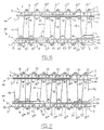
- a second tension warp thread (9', 10') was added to every warp thread system.
- a fourth variant method differs from the third variant method in that the weft threads (6, 7, 8) are bound in by the binder warp threads (3, 4) in a different manner.
- the binding in of the weft threads takes place in such a manner that in each case the second (7) and third weft threads (8) extend through successive openings (49-55) between the binder warp threads (3, 4), while the first weft threads (6) in each case extend through an opening (49'', 50'') which is formed between, on the one hand, two binder warp threads (3, 4) and, on the other hand, the tension warp thread (9, 10). Because the first weft threads in each case extend through a separate opening and are consequently separated from the adjacent second and third weft threads, they can no longer penetrate the second and third weft threads. The disadvantages indicated above which resulted from said penetration are thus eliminated.
- the face-to-face pile fabric according to Figure 12 differs from that according to Figure 10 in that a second tension warp thread (9', 10') was added to every warp thread system in each fabric (TF, BF), which results in the abovementioned advantages.
- the tension warp thread (9, 10) is bound in on the back of the fabric relative to the first weft threads (6), while the crossing of binder warp threads (3, 4) relative to the first weft threads (6) is in each case provided on the pile side, so that the openings (49'', 50'', ...) are formed between, on the one hand, the crossing binder warp threads (3, 4) and, on the other hand, the tension warp thread (9, 10).
- a fifth variant method according to this invention differs from the third and fourth variant method in that the weft threads (6, 7, 8) are bound in by the binder warp threads (3, 4) in yet another manner.
- the binding in of the weft threads (6, 7, 8) takes place such that in each case the second (7) and third weft threads (8) extend through successive openings (49-55) between the binder warp threads (3, 4), while the first weft threads (6) in each case extend through an opening (49''', 50''', ...) which is formed between, on the one hand, the two binder warp threads (3, 4) and, on the other hand, at least one dead pile warp thread (11-16).
- first deft threads (6) in each case extend through separate openings (49''', 50''', ...) as well and are consequently separated from the adjacent second (7) and third weft threads (8) which extend through the adjacent openings (49-55). These first weft threads (6) can therefore no longer penetrate said adjacent second (7) and third weft threads (8) as a result of which a drawn pile is prevented (and thus mixing contours as well).
- the face-to-face pile fabric according to Figure 13 differs from that of Figure 11 in that a second tension warp thread (9', 10') was added to every warp thread system in each fabric (TF, BF) which results in the abovementioned advantages.
- the dead pile warp threads (11-16) are bound in on the pile side of the fabric (TF, BF) relative to the first weft threads (6), while the crossing of the binder warp threads (3, 4) relative to the first weft threads (6) is in each case provided on the back, so that the openings (49''', 50''', ...) are formed between, on the one hand, the crossing binder warp threads (3, 4 ) and, on the other hand, at least one dead pile warp thread (11-16).
- the dead pile warp threads (11-16) are bound in on the pile side of the fabric (BF, TF) relative to the first weft threads (6) in order to prevent their colour showing through on the back of the fabric.
- the tension warp thread (9, 10) runs on the back of the fabric (BF, TF) relative to the first weft threads (6) and the pile-forming pile warp threads (11-14) are interlaced with the third weft threads (8).
- the resulting fabrics are pile fabrics where the pile passes through.
- both pile warp threads (12, 13) marry at that location (X) between the top fabric (TF) and the bottom fabric (BF). This is referred to as double pile warp threads (see Figures 16 and 17).
- the double pile warp threads can be eliminated in a quick and relatively simple manner by going through this data file containing software and finding the locations where a pile change, as described above, takes place and omit a loop knop at those locations.
- This omission takes place in the forward or backward direction, in the direction where there is more than one pile knop.
- Figure 18 shows a cross section of a face-to-face pile fabric where pile passes through and having in each case an additional tension warp thread (9', 10') in the top fabric (TF) and in the bottom fabric (BF).
- This fabric is manufactured according to the fourth variant method according to this invention. However, the following applies to all variant methods according to this invention where pile is formed on the third weft threads (8).
- the second weft threads (7) are chosen to be thinner than the other weft threads (6), (8). This results in the sides of the pile loops being pushed apart to a lesser degree. It is also possible to choose the second weft threads (7) and the first weft threads (6) to be thinner than the third weft threads (8). In addition to the aforementioned advantage, this also has the advantage that the fabric back becomes less thick, as a result of which the part of the pile knop which is located in the back is shortened leading to a saving in pile material.
- the relatively thick weft on the back ensures a clear pattern on the back and prevents the colour of the bound-in dead pile warp threads from showing through on the back.
- the backs of the bottom fabric (BF) and of the top fabric (TF) have an identical pattern: the design pattern.
- This method using relatively thin weft threads (7), and (6), (7), respectively, can also be used with face-to-face pile fabrics where pile does not pass through (see Figures 20 and 21).
- FIGs 4 to 7 inclusive illustrate several cases where relatively thin weft threads (6, 7, 8) are used, in which the weft threads (6, 7, 8) and a pile loop are shown of a fabric which has been manufactured according to the first variant method according to the invention.
- the desired positions relative to the successive weft threads (6, 7, 8) are stored in the form of a set of control data.
- This set is incorporated, for example, in a card design which is processed to form a data file or to control a jacquard device. During weaving, this jacquard device can position the pile warp threads in accordance with the input control data.
- the same set of control data can be used both for manufacturing a face-to-face pile fabric where pile passes through and for manufacturing a face-to-face pile fabric where pile does not pass through, as the pile-formation only has to be moved one pick in order to obtain either one or the other face-to-face pile fabric.
- the binder warp threads (3, 4), the tension warp threads (9, 10), (9', 10') and the pile warp threads (11-16) are taken to a level prior to every pick (or shot) relative to the respective weft insertion heights of the three weft insertion means (21, 22, 23) of a triple weft insertion mechanism such that these threads (3, 4, 9, 9', 10, 10', 11-16), after the insertion of the weft threads (6, 7, 8), extend in the top fabric (TF) and the bottom fabric (BF), in the position required according to the desired weave relative to the weft threads (6, 7, 8).
- the warp threads (3, 4, 9, 9', 10, 10', 11-16) extend through the reed (20). After the weft threads (6, 7, 8) have been inserted, they are pushed by the reed (20) to the edge of the face-to-face pile fabric (TF), (BF) already formed.
- TF face-to-face pile fabric
- the binder warp threads (3, 4) and the tension warp threads (9, 10), (9', 10') are positioned, for example, by means of heald frames, while the pile warp threads (11-16) are positioned by means of a jacquard mechanism.
- the triple weft insertion mechanism alternately inserts two weft threads (7, 8) into the top fabric (TF) and one weft thread (6) into the bottom fabric (BF), or two weft threads (7, 8) into the bottom fabric (BF) and one weft thread (6) into the top fabric (TF), respectively.
- the top weft insertion means (21) alternately inserts a weft thread (6) and a weft thread (8) into the top fabric (TF).
- the bottom weft insertion means (13) alternately inserts a weft thread (8) and a weft thread (6) into the bottom fabric (BF).
- the centre weft insertion means (22) alternately inserts a weft thread (7) into the bottom fabric (BF) and a weft thread (7) into the top fabric (TF).
- the tension warp threads (9, 10), (9', 10') serve as a guide for the weft insertion means (21, 22, 23).
- the tension warp thread (9) of the top fabric (TF), the tension warp thread (10') of the bottom fabric (BF) and the tension warp thread (10) of the bottom fabric (BF) form a guide for the top (21), centre (22) and bottom (23) weft insertion means, respectively.
- the dead pile warp threads (11-14) do not have to fulfil this guide function and they are prevented from being damaged or breaking.
- fabrics are produced which only differ from the second variant method ( Figures 2 and 3) in that the pile-forming pile warp threads (11-14) are in each case interlaced with the first weft threads (6).
- Figures 25 to 28 inclusive illustrate the weft threads (6, 7, 8) and a pile loop of a fabric which was manufactured according to this sixth variant method, and where (Fig. 26-28) the second (7) and/or the third weft thread (8) are chosen to be thinner than the other weft thread or weft threads.
Abstract
- in each case forming pile on the first weft thread (6) which is provided on the back of the second (7) and third weft thread (8);
- binding in the dead pile warp thread (11-16) distributed over both fabrics (TF, BF);
- in each case forming pile on the third weft thread (8) located on the back while a pile thread which starts forming pile or finishes forming pile is first interlaced with a third weft thread before it starts forming pile or is bound in;
- binding in the first weft thread (6) by means of binder warp threads (3, 4) in each case in a separate opening (49', 50', ...; 49'', 50'', 49''', 50''',...);
- in each case forming pile on the first weft thread (6) which is not provided on the back of the fabrics (TF, BF);
- providing two tension warp threads (9, 10); (9', 10') in each warp thread system.
Description
- The present invention relates to a method for manufacturing a face-to-face pile fabric, in which
- a top fabric and a bottom fabric are formed by providing successive groups of three weft threads for each fabric, so that, in every group, a first weft thread extends next to a second and a third weft thread, which are located one above the other, by providing, for each fabric, adjacent warp thread systems having two binder warp threads which cross a number of times so as to form successive openings between their points of intersection, through which extends in each case a group of weft threads, and by binding a tension warp thread into each fabric in each of the warp thread systems;
- in each case three weft threads are inserted simultaneously;
- in accordance with a three-pick weave, in each of the warp thread systems at least one pile-forming pile warp thread is interlaced with a weft thread, alternately in the top fabric and in the bottom fabric;
- and all pile-forming pile warp threads between both fabrics are cut through in order to obtain two separate pile fabrics.
- Such a method is known from FR-2.182.790.
- According to this known method, the pile-forming pile warp threads are in each case interlaced with the third weft threads located on the back of the fabrics (except in case of a change of pile).
- In each case, two weft threads are inserted simultaneously into one fabric and one weft thread into the other fabric, a weaving loom thus inserting six weft threads in two working cycles.
- According to this method, the dead pile warp threads (i.e. the pile warp threads or parts of pile warp threads which do not form pile) are alternately bound into the top fabric and into the bottom fabric in the successive warp thread portees (a warp thread portee consists of a warp thread system of the top fabric and a warp thread system of the bottom fabric, whose binder warp threads, tension warp threads and pile warp threads are located one above the other).
- After the face-to-face fabric has been cut through, each fabric comprises successive rows of pile loops which have been interlaced with corresponding weft threads. These pile loops have upright pile sides. In order to achieve perfect pile formation, these pile sides have to extend at right angles to the plane of the backing fabric (which comprises weft threads, binder warp threads and tension warp threads). If this is not the case (i.e. with a so-called drawn pile), a fabric of inferior quality is obtained. As a result of a drawn pile, mixing contours may occur in the fabrics.
- If the pile sides form different colour fields in a pile fabric (in order to produce a design or pattern), mixing contours occur when pile sides of a different colour are visible among pile sides of one colour on the pile surface of the fabrics. This is caused as a result of pile sides of one colour extending at an angle among the pile sides of another colour in the vicinity of the separation line between two colour fields, and being visible at the pile surface of the fabric.
- The colours mix and the fabrics have no clearly defined separation line between adjacent colour fields.
- The fabric produced according to the method of FR-2.182.790 exhibits a drawn pile.
- It is an object of this invention, to provide a method for manufacturing a face-to-face pile fabric by means of which a drawn pile is prevented while binding in the dead pile warp threads in each warp thread portee distributed over both fabrics.
- It was found that the drawn pile was a result of the fact that the first weft threads penetrate the second and third weft threads lying above one another. The upright sides of the pile loops therefore tend to spread out, thereby not remaining in the desired upright position as the face-to-face pile fabric is cut through.
- The abovementioned object is achieved according to this invention in that the first weft threads of successive groups extend in a first plane, which lies on the back relative to a second and third plane in which, respectively, the second and third weft threads of these successive groups extend, because the pile-forming pile warp threads are in each case interlaced with a first weft thread, and because the dead pile warp threads are bound in in each warp thread portee, distributed over both fabrics.
- Thus, two weft threads (the second and third weft threads), one above the other, are located in each case on either side of a pile loop. These weft threads keep the pile sides upright. In addition, the first weft thread is prevented from penetrating the second and third weft threads located above one another.
- As a result, the pile sides remain in the desired position after the face-to-face pile fabric is cut through, at right angles to the plane of the backing fabric, so that a drawn pile no longer occurs.
- Furthermore, the quality of the fabrics is also improved as the dead pile warp threads are bound in in each warp thread portee distributed over both fabrics.
- With the known method according to FR-2.182.790, the pile warp threads which finish forming pile are interlaced with a second weft thread in a first warp thread portee before they are bound into the top fabric, and the pile warp threads which start forming pile are interlaced with a third weft thread before they start to form pile (run to the bottom fabric).
- In a subsequent warp thread portee, the pile warp threads which finish forming pile are interlaced with a third weft thread before they are bound into the bottom fabric, and the pile warp threads which start forming pile are interlaced with a second weft thread before they start forming pile (run to the top fabric).
- The face-to-face pile fabric has alternating first and second warp thread portees.
- In each fabric, there are thus pile warp threads which interlace with second weft threads (located on the side of the pile).
- The pile sides thus formed are not visible on the back of the fabrics. The pattern of the pile fabrics is thus not completely visible on the back of the fabrics. Moreover, the visible part of the pattern appears as a dashed line.
- An additional object of this invention is to produce the complete pattern of the pile fabrics clearly on the back of the fabrics.
- If, in the known method, the dead pile warp threads were to be bound in distributed over both fabrics, this would lead to mixing contours. When a first pile warp thread which was bound into one fabric starts forming pile (runs to the other fabric) and a second pile warp thread which was forming pile runs to said other fabric in order to be bound into the latter, both pile warp threads jointly run between both fabrics. This causes mixing contours after the face-to-face pile fabric is cut through.
- In order to prevent mixing contours, it should be ensured that, with the pile warp threads which have a pile-forming part which changes into a bound-in part and/or a bound-in part that changes into a pile-forming part, a last or a first pile side, respectively, of said pile warp threads remains upright relative to the backing fabric after the fabrics have been cut through.
- Mixing contours are prevented and the complete pattern of the pile fabrics appears clearly on the back by means of interlacing a pile warp thread with a first weft thread, before said pile warp thread is bound in or starts forming pile, respectively.
- In this manner, said first and last pile sides are also laterally supported by weft threads located one above the other, after the face-to-face pile fabric has been cut through. The pile sides remain upright, thereby preventing mixing contours. Moreover, each pile side is interlaced with a weft thread on the back, so that the pattern is clearly and completely visible on the back of the fabrics.
- With a method as described in the first paragraph of this description, where at least one pile-forming pile warp thread has a part which forms pile because it is interlaced with a third weft thread in each case, and has another part that is bound into a fabric in the form of dead pile warp thread, the quality of the resulting fabrics can likewise be improved.
- Such fabrics are obtained according to the method described in FR-2.182.790.
- These known fabrics do not show the complete pattern of the pile fabric on the back and the dead pile warp threads are not bound in in each warp thread portee distributed over both fabrics. Furthermore, the visible part of the pattern appears as a dashed line. If, with this method, the dead pile warp threads were to be bound in distributed over both fabrics, this would cause mixing contours (see above).
- It is also an object of this invention, with such fabrics (where the pile-forming pile warp threads are interlaced with the third weft threads), to show the pattern clearly and completely on the back of the fabrics, as well as to bind in the dead pile warp threads in each warp thread portee distributed over both fabrics while preventing mixing contours.
- This object is achieved in that, in each warp thread portee both at a transition from a pile-forming part to a bound-in part and at a transition from a bound-in part to a pile-forming part of a pile warp thread, said pile warp thread is interlaced with a third weft thread before it is bound in or starts forming pile, respectively, and in that the dead pile warp threads in each warp thread portee are bound in distributed over both fabrics.
- As all pile sides are now interlaced with a weft thread on the back, the pattern of the fabric is clearly and completely visible on the back of the fabrics.
- The dead pile warp threads are bound in in each warp thread portee distributed over both fabrics. Mixing contours are prevented because all pile sides are supported by adjacent (first) weft threads, so that they remain in the desired upright position after the face-to-face pile fabric has been cut through.
- With the method described in the first paragraph of this description, the first weft thread can also be prevented from penetrating the second and third weft threads lying one above the other by a special way of binding the weft threads in by means of the binder warp threads.
- The groups of weft threads are no longer provided in each case in one opening between the binder warp threads but are distributed in each case over two successive openings, so that a first weft thread or a second weft thread and a third weft thread, respectively, alternately extends between the binder warp threads. Moreover, the dead pile warp threads are bound in distributed over both fabrics in each warp thread portee in order to improve the quality of the fabric.
- In this way, the first weft thread is in each case bound into an individual opening, separate from the adjacent second and third weft threads. The disadvantageous penetration of the second and third weft threads by the first weft threads is thus prevented. The above-mentioned disadvantages which are caused by said penetration are thus overcome by this method according to the invention.
- In the method described in the first paragraph of this description (and in which the dead pile warp threads are bound into one of the fabrics or divided over both fabrics), the penetration of adjacent second and third weft threads by the first weft threads can also be prevented by another special way of binding in the weft threads. In this case, a complete group of weft threads is also no longer always provided in the successive openings between the binder warp threads.
- The binding in of the weft threads takes place in such a manner that in each case the second and third weft threads extend through said successive openings while the first weft threads extend in each case through an opening which is formed between, on the one hand, two binder warp threads and, on the other hand, the tension warp thread or through an opening which is formed between, on the one hand, the two binder warp threads and, on the other hand, at least one dead pile warp thread.
- As the first weft threads in each case extend through individual openings and are consequently separated from the adjacent second and third weft threads, they can no longer penetrate said second and third weft threads. The abovementioned disadvantages which resulted from said penetration are consequently eliminated.
- According to a first possibility, the tension warp thread is bound in on the back of the fabric relative to the first weft threads, while the crossing of binder warp threads relative to the first weft threads is provided in each case on the pile side, so that the successive openings are formed between the crossing binder warp threads, on the one hand, and the tension warp thread, on the other.
- According to a second possibility, the dead pile warp threads are bound in on the pile side of the fabric relative to the first weft threads, while the crossing of the binder warp threads relative to the first weft threads is provided in each case on the back, so that the successive openings are formed between the crossing binder warp threads, on the one hand, and at least one dead pile warp thread, on the other.
- In the above-described methods, where the penetration of the second and third weft thread by the first weft thread is in each case prevented by a special way of binding in the weft threads using the binder warp threads, mixing contours are likewise prevented by first interlacing a pile warp thread which starts forming pile or finishes forming pile, respectively, with a third weft thread before it starts forming pile or is bound in, respectively.
- The method as described in the first paragraph of this description can also be carried out in such a manner that the pile-forming pile warp threads are not visible on the back of the fabric (fabrics where pile is not passed through). This is achieved by interlacing the pile-forming pile warp threads in each case with the first weft threads (not located on the back) of successive groups of weft threads. In addition, the dead pile warp threads are bound in divided over both fabrics and in each warp thread portee so as to improve the quality of the fabrics.
- As the third weft threads on the back of the resulting fabrics are not used for interlacing pile threads, such fabrics are suitable in particular for gluing onto surfaces, for example on a floor or walls. Since, in addition, the adhesive is only present between the weft threads on the back and the surface, the flexibility of the fabric pile threads is not affected, yet the adhesion of the fabric on the surface is excellent. The pile thread loops of the active pile do not come into contact with the surface and will therefore not be subject to wear. Moreover, this method requires less pile thread to achieve a certain effective pile height.
- The methods according to this invention where the pile-forming pile warp threads are interlaced with third weft threads in order to produce fabrics where pile passes through, can be modified to a method where the pile-forming pile warp threads are interlaced with first weft threads to produce fabrics where pile does not pass through by allowing the interlacing of the pile warp threads to take place one pick earlier or one pick later. This requires only a minor modification of the control data for the device (such as, for example, a jacquard loom) for positioning the pile warp threads relative to the successive weft threads.
- In a preferred method according to this invention, the first and third weft threads are provided such that they extend in planes lying one above the other, while the tension warp threads are in each case bound in such that they extend between said first and third weft threads.
- As a result, the dead pile warp threads bound into the fabrics are protected on the back by these tension warp threads.
- If the pile-forming pile warp threads are in each case interlaced with the weft thread (the first or third weft thread, depending on the method used according to this invention) running on the back of the tension warp thread, the pattern of the pile fabric is very accurate and clearly visible on the back of the pile fabrics.
- A fabric (in particular, a carpet) which is weaved according to a three-pick weave tends to curl towards the back. This is caused by the fact that, on the one hand, the pile warp thread bound in on the back prevents the elongation or extension of the fabric on the back, while, on the other hand, the bound-in dead pile warp threads push the fabric apart on the pile side.
- Moreover, the weft threads situated on the pile side of the dead pile warp threads may push these dead pile warp threads between successive weft threads against the tension warp threads, as a result of which dead pile warp treads are bound in in a wave-like manner and causing increased pile consumption.
- An additional object of this invention is to eliminate these disadvantages. This object is achieved in that a second tension warp thread is provided for every warp thread system in each fabric. This second tension warp thread is bound in between the second and third weft threads so that only the second weft threads extend on the pile side of this second tension warp thread.
- The first tension warp thread extends between the first and third weft threads of every warp thread system.
- As a result of this second tension warp thread, the fabric can not extend on the pile side and curling is prevented. In addition, the weft threads running on the pile side press the dead pile warp threads against the first tension warp threads. The dead pile warp threads remain extended and pile consumption for binding in remains at a minimum.
- When using two tension warp threads in every warp thread system, the warp threads of a warp thread system can be arranged next to one another in the following order: the first tension warp thread, the two binder warp threads, the second tension warp thread, the pile warp threads. The pile warp threads are thus in each case situated between two tension warp threads (the second tension warp thread of a warp thread system and the first tension warp thread of a subsequent warp thread system). The pile sides are consequently out of range of the binder warp threads, so that these binder warp threads cannot affect the orientation of the pile sides. Thus the pile sides assume the desired upright position and form straighter lines in the warp direction on the pile surface. This results in the pile sides not mixing with pile sides of an adjacent row of pile loops.
- Furthermore, an additional tension warp thread may serve as a guide for the weft insertion means so that dead pile warp threads do not have to carry a weft insertion means which could result in them being damaged or breaking as a consequence of their contact with a weft insertion means.
- The addition of a further tension warp thread in each fabric, as described above, can also be achieved using a method where the weft threads are bound in in a different manner than described above. By allowing both tension warp threads to run in such a manner that they are separated by the single weft threads, they extend above one another, thereby preventing curling of the pile fabric. By ensuring that a tension warp thread extends in each case on either side of the pile warp threads, straighter pile rows are achieved. Both measures can be applied separately or in combination.
- With the method for manufacturing a face-to-face pile fabric where pile does not pass through, mixing contours are prevented by interlacing a pile warp thread which starts forming pile or finishes forming pile, respectively, with a first weft thread before it starts forming pile or is bound in, respectively.
- By binding in the dead pile warp threads in such a manner that they extend between the second and third weft threads and extend on the pile side of the fabric relative to the first weft threads, the bound-in dead pile warp threads do not show through on the back of the pile fabrics, resulting in an identical appearance of the back of both pile fabrics. (After all, pile warp threads that are bound into the top fabric differ in colour from the pile warp threads that are bound into the bottom fabric).
- It is important that, in the above-described methods according to this invention, double pile warp threads do not occur.
- Double (married) pile warp threads occur when a pile change is effected (when a first pile warp thread which formed pile from a certain pick onwards is bound in and a second pile warp thread which was bound in starts forming pile from the same pick onwards) in the face-to-face fabric, between a first pile warp thread which is to be bound into one fabric after the pile change and a second pile warp thread which was bound into the other fabric before the pile change.
- The marriage of these pile warp threads between top fabric and bottom fabric results in so-called mixing contours (a pile side in one coloured area extends into another colour field) causing poor delineation on the pile surface between adjacent colour fields.
- This is prevented by omitting a pile loop, or in other words by either binding the first pile warp thread into the pile fabric two picks earlier than the fixed pick or the second pile warp thread starting to form pile two picks later than the fixed pick.
- The pile warp thread whose pile loop is omitted is set so that the omission takes place in the direction where there is more than one pile loop.
- The method according to this invention can be implemented to great effect, using a triple weft insertion mechanism with which, alternately, a second and third weft thread are provided in the bottom fabric and a first weft thread in the top fabric, or a second and third weft thread in the top fabric and a first weft thread in the bottom fabric, respectively.
- In a particularly preferred method according to this invention, at least one weft thread of the two weft threads of each group with which no pile warp thread is interlaced, is chosen to be thinner than the other weft threads of that group.
- The pile-forming pile warp threads are thus interlaced in each case with a relatively thick weft thread while one or both of the other weft threads are relatively thin.
- In the case of a pile fabric where pile passes through, this results in the pattern becoming visible even more clearly on the back, and the colour of the bound-in dead pile warp threads not showing through on the back. Thus, both pile fabrics have an identical back which clearly shows the pattern.
- An additional advantage thereof is the fact that the sides of the pile loops are pushed apart to a lesser degree if a relatively thin weft thread extends between these sides. This results in sides which are more upright which again serves to produce a clear and straight delineation of the pile fabric pattern.
- The characteristics of the methods according to this invention are explained in the following description of a number of non-restricting examples of face-to-face pile fabrics manufactured in accordance with this method.
- In this description, reference is made to the attached figures, in which:
- Figure 1 shows a cross section of a face-to-face pile fabric where pile passes through, manufactured according to a first variant method according to this invention;
- Figures 2 and 3 show a cross section of a face-to-face pile fabric where pile passes through, manufactured according to a second variant method according to this invention;
- Figure 4 shows the mutual position of the weft threads in a fabric of Figure 2 or 3;
- Figures 5 to 7 inclusive show the mutual position of the weft threads in a fabric, manufactured according to the second variant method, where weft threads of different thickness are provided;
- Figures 8 and 9 show a cross section of a face-to-face pile fabric where pile passes through, manufactured according to a third variant method according to this invention, where one tension warp thread is provided for every warp thread system (Fig. 8) or two tension warp threads are provided for every warp thread system (Fig. 9), respectively;
- Figures 10 and 12 show a cross section of a face-to-face pile fabric where pile passes through, manufactured according to a fourth variant method according to this invention, where one tension warp thread is provided for every warp thread system (Fig. 10) or two tension warp threads are provided for every warp thread system (Fig. 12), respectively;
- Figures 11 and 13 show a cross section of a face-to-face pile fabric where pile passes through, manufactured according to a fifth variant method according to this invention, where one tension warp thread is provided for every warp thread system (Fig. 11) or two tension warp threads are provided for every warp thread system (Fig. 13), respectively;
- Figures 14 and 15 show a cross section of a face-to-face pile fabric where pile does not pass through, having one tension warp thread for every warp thread system, manufactured according to the fourth (Fig. 14) or fifth (Fig. 15) variant method, respectively, according to this invention;
- Figure 16 shows a cross section of the face-to-face pile fabric according to Figure 12 before the correction of the pile change;
- Figure 17 shows a cross section of the face-to-face pile fabric according to Figure 14, having an additional tension warp thread for every warp thread system, and before the correction of the pile change;
- Figure 18 shows a cross section of the face-to-face pile fabric according to Figure 12, having in each case one relatively thin second weft thread on the pile side of the fabrics;
- Figure 19 shows a cross section of the face-to-face pile fabric according to Figure 10, having in each case one relatively thin first and second weft thread and a relatively thick third weft thread on the back of the fabrics;
- Figure 20 shows a cross section of the face-to-face pile fabric according to Figure 17, having in each case one relatively thin second weft thread and a relatively thick first and third weft thread;
- Figure 21 shows a cross section of the face-to-face pile fabric according to Figure 14, having in each case one relatively thin first and second weft thread and a relatively thick third weft thread on the back of the fabrics;
- Figure 22 shows a diagrammatic representation of the positions of the tension warp threads, binder warp threads and pile warp threads relative to the three weft insertion means of a triple weft insertion mechanism during weaving according to the invention of a face-to-face pile fabric having two tension warp threads for each fabric, on a face-to-face weaving loom;
- Figures 23 and 24 show a cross section of a face-to-face pile fabric where pile does not pass through, manufactured according to a sixth variant method according to this invention;
- Figure 25 shows the mutual positions of the weft threads in a fabric of Figure 23 or 24;
- Figures 26 to 28 inclusive show the mutual positions of the weft threads in a fabric manufactured according to the sixth variant method, where weft threads having different thicknesses are provided.
- According to all variant methods of this invention, a face-to-face pile fabric is manufactured by forming a top fabric (TF) and a bottom fabric (BF). Both fabrics (TF, BF) are formed by providing for each fabric in each case successive groups of three weft threads (6, 7, 8), so that, in every group, a first weft thread (6) extends next to a second (7) and a third weft thread (8), which are located one above the other, and by providing, for each fabric (TF, BF), adjacent warp thread systems having two binder warp threads (3, 4), one or more tension warp threads (9, 10; 9', 10') and one or more pile warp threads (11-16).
- These binder warp threads (3, 4) cross each other a number of times so as to provide successive openings (49-55; 49, 49', 50, 50'; 49, 49'', 501 50''...; 49, 49''', 50, 50'''...) between their points of intersection, through which extend in each case one or more weft threads (6, 7, 8). In this manner, the weft threads (6, 7, 8) are bound into the respective fabrics (TF, BF). The tension warp threads (9, 10;, 9', 10') are bound into the respective fabrics (TF, BF) in each of the warp thread systems. The pile-forming pile warp threads (11-14) are interlaced with a weft thread (6, 8) alternately in the top fabric (TF) and in the bottom fabric (BF) in accordance with a three-pick weave.
- A dead pile warp thread (11-16) is bound into one of the fabrics (TF, BF).
- A pile warp thread (11-14) may have a part which forms pile and another part which may be bound in as dead pile warp thread.
- The face-to-face pile fabric is manufactured on a face-to-face weaving loom provided with a triple weft insertion means (21, 22, 23, in Figure 22), by means of which in each case three weft threads (6, 7, 8) are inserted simultaneously.
- In a first operating cycle, a second (7) and a third weft thread (8) are inserted into the top fabric (TF) and a first weft thread (6) is inserted into the bottom fabric (BF).
- In a second (subsequent) operating cycle, a first weft thread (6) is inserted into the top fabric (TF) and a second (7) and third weft thread (8) are inserted into the bottom fabric (BF).
- By inserting six weft threads (6, 7, 8) in two working cycles of the weaving loom, very efficient weaving is achieved.
- In accordance with a first variant method (see Figure 1) according to this invention, a face-to-face carpet is manufactured, in which case the first weft threads (6) are provided in a plane on the back relative to the two planes above one another, through which the second (7) and third weft threads (8), respectively, extend.
- The binder warp threads (3, 4) cross a number of times and form successive openings (49-55) through which extend in each case a second (7) and a third weft thread (8), one above the other, followed by a first weft thread (6).
- In each fabric (TF, BF), in every warp thread system, a first tension warp thread (9, 10) is bound in which extends between the first weft threads (6) and the third weft threads (8).
- Furthermore, in each fabric (TF, BF), in every warp thread system, a second tension warp thread (9', 10') is bound in which extends between the second (7) and third weft threads (8).
- The dead pile warp threads (11-16) are bound in, divided over both fabrics (TF, BF), and extend between the second (7) and third weft threads (8). The pile-forming pile warp threads (11-13) are in each case interlaced with the first weft threads (6). After the face-to-face fabric has been cut through (cf. diagrammatic representation of cutting means in Figure 1), the pile sides are supported by the second (7) and third weft threads (8) which extend next to one another. In this manner, an upright pile is produced and mixing contours are prevented.
- The first tension warp thread (9, 10) protects the dead pile warp threads (11-16) on the back of the carpet.
- Since only the first weft threads (6), on which pile is formed, extend on the back of the first tension warp thread (9, 10), the pattern is very clearly visible on the back of the carpet. The dead pile warp threads can be prevented from showing through on the back of the carpet by means of the first tension warp threads (9, 10).
- The pattern is represented in full on the back of the carpet because a pile warp thread (12, 13) is interlaced with a first weft thread (6) at the transition from a bound-in part to a pile-forming part, before it starts forming pile, and because a pile warp thread (11, 12) is interlaced with a first weft thread (6) at the transition from a pile-forming part to a bound-in part, before it is bound in.
- According to a second variant method (see Figures 2 and 3) according to this invention, a face-to-face carpet is manufactured, in which case the first weft threads (6) are provided in a plane situated between the two planes lying one above the other in which the second (7) and third weft threads (8), respectively, extend. In each case a first weft thread (6) followed by the second (7) and third weft threads (8) lying one above the other are provided through the openings (49-55) between the binder warp threads (3, 4) which cross a number of times. The dead pile warp threads (11-16) and the first tension warp threads (9, 10) are bound in in the same manner as with the first variant method, and thus result in the same advantages. The pile-forming pile warp threads (11-14) are in each case interlaced with third weft threads (8) situated on the back. The pile warp threads (11, 12, 13), a bound-in part of which changes to a pile-forming part, and the pile warp threads (11, 12, 14), a pile-forming part of which changes to a bound-in part, are interlaced first with a third weft thread (8) before they start forming pile or are bound in, respectively.
- In this manner, mixing contours are prevented and the pattern is clearly and completely visible on the back of the carpet.
- In accordance with a third variant method (see Figures 8 and 9) according to this invention, a face-to-face carpet is manufactured, in which case the weft threads (6, 7, 8) are in the same positions as with the second variant method. Likewise, the dead pile warp threads (11-16) and the first tension warp thread (9, 10) are bound into the fabrics (TF, BF) in the same manner as with the second variant method.
- The pile-forming pile warp threads (11-14) also form pile along the third weft threads (8) situated on the back. At the start and at the finish of the pile formation, a pile warp thread (11-14) is first interlaced with a third weft thread (8) before it starts forming pile or is bound in, respectively.
- The difference with the second variant method is the fact that the first weft thread (6) is enclosed in each case in a separate opening (49', 50'...) by the binder warp threads (3, 4).
- In every warp thread system there is a first binder warp thread (3) which successively interlaces the first (6) and the third weft threads (8) with the first tension warp thread (9, 10) and there is a second binder warp thread (4) which in each case interlaces the second weft thread (7) between the pile sides so that it is separated from the first weft thread (6).
- In this manner, crossings of the binder warp threads (3, 4) are achieved on both sides of the first weft threads (6).
- The binder warp threads (3, 4) thus form successive openings (49, 49', 50, 50', ...) through which alternately a first weft thread (6) or a second (7) and third weft thread (8), respectively, extend.
- The first weft thread (6) thus extends in each case through a separate opening (49', 50', . ..) which is located between two openings (49, 50; 50, 51), through which in each case the adjacent second (7) and third weft threads (8) extend.
- In this way, the first weft threads (6) can no longer penetrate the adjacent second (7) and third weft threads (8), as a result of which a drawn pile is prevented (and thus mixing contours as well).
- Figure 9 differs from Figure 8 in that a second tension warp thread (9', 10') was added to every warp thread system. The abovementioned advantages resulting from the use of two tension warp threads (9, 10), (9', 10') in every warp thread system are therefore also obtained with this variant method.
- A fourth variant method (see Figures 10 and 12) according to this invention differs from the third variant method in that the weft threads (6, 7, 8) are bound in by the binder warp threads (3, 4) in a different manner.
- The binding in of the weft threads takes place in such a manner that in each case the second (7) and third weft threads (8) extend through successive openings (49-55) between the binder warp threads (3, 4), while the first weft threads (6) in each case extend through an opening (49'', 50'') which is formed between, on the one hand, two binder warp threads (3, 4) and, on the other hand, the tension warp thread (9, 10). Because the first weft threads in each case extend through a separate opening and are consequently separated from the adjacent second and third weft threads, they can no longer penetrate the second and third weft threads. The disadvantages indicated above which resulted from said penetration are thus eliminated.
- The face-to-face pile fabric according to Figure 12 differs from that according to Figure 10 in that a second tension warp thread (9', 10') was added to every warp thread system in each fabric (TF, BF), which results in the abovementioned advantages.
- The tension warp thread (9, 10) is bound in on the back of the fabric relative to the first weft threads (6), while the crossing of binder warp threads (3, 4) relative to the first weft threads (6) is in each case provided on the pile side, so that the openings (49'', 50'', ...) are formed between, on the one hand, the crossing binder warp threads (3, 4) and, on the other hand, the tension warp thread (9, 10).
- A fifth variant method according to this invention (see Figures 11 and 13) differs from the third and fourth variant method in that the weft threads (6, 7, 8) are bound in by the binder warp threads (3, 4) in yet another manner.
- The binding in of the weft threads (6, 7, 8) takes place such that in each case the second (7) and third weft threads (8) extend through successive openings (49-55) between the binder warp threads (3, 4), while the first weft threads (6) in each case extend through an opening (49''', 50''', ...) which is formed between, on the one hand, the two binder warp threads (3, 4) and, on the other hand, at least one dead pile warp thread (11-16).
- In this case, the first deft threads (6) in each case extend through separate openings (49''', 50''', ...) as well and are consequently separated from the adjacent second (7) and third weft threads (8) which extend through the adjacent openings (49-55). These first weft threads (6) can therefore no longer penetrate said adjacent second (7) and third weft threads (8) as a result of which a drawn pile is prevented (and thus mixing contours as well).
- The face-to-face pile fabric according to Figure 13 differs from that of Figure 11 in that a second tension warp thread (9', 10') was added to every warp thread system in each fabric (TF, BF) which results in the abovementioned advantages.
- The dead pile warp threads (11-16) are bound in on the pile side of the fabric (TF, BF) relative to the first weft threads (6), while the crossing of the binder warp threads (3, 4) relative to the first weft threads (6) is in each case provided on the back, so that the openings (49''', 50''', ...) are formed between, on the one hand, the crossing binder warp threads (3, 4 ) and, on the other hand, at least one dead pile warp thread (11-16).
- The dead pile warp threads (11-16) are bound in on the pile side of the fabric (BF, TF) relative to the first weft threads (6) in order to prevent their colour showing through on the back of the fabric.
- The tension warp thread (9, 10) runs on the back of the fabric (BF, TF) relative to the first weft threads (6) and the pile-forming pile warp threads (11-14) are interlaced with the third weft threads (8). The resulting fabrics are pile fabrics where the pile passes through.
- In Figures 14 and 15 the pile-forming pile warp threads (11-14) are interlaced with the first weft threads (6).
- In Figure 14, the first weft threads (6) are bound in according to the fourth variant method according to this invention.
- In Figure 16, the first weft threads (6) are interlaced according to the fifth variant method according to this invention.
- When a pile-forming pile warp thread (12) is bound in from a certain pick onwards in one fabric, for example the bottom fabric (BF), and when a bound-in pile warp thread (13) starts forming pile from the same pick onwards, both pile warp threads (12, 13) marry at that location (X) between the top fabric (TF) and the bottom fabric (BF). This is referred to as double pile warp threads (see Figures 16 and 17).
- These double pile warp threads (12, 13) cause mixing contours. Eliminating the pile loop prevents the two pile warp threads (12, 13) marrying. In essence, the pile warp thread (12) which has to finish forming pile is bound into the bottom fabric (BF) two picks earlier or the pile warp thread (13) which has to start forming pile starts forming pile two picks later.
- If the binding-in data necessary to implement the methods according to this invention are stored in a data file of a computer, the double pile warp threads can be eliminated in a quick and relatively simple manner by going through this data file containing software and finding the locations where a pile change, as described above, takes place and omit a loop knop at those locations.
- This omission takes place in the forward or backward direction, in the direction where there is more than one pile knop.
- After correction of the pile change in the weave according to Figure 16, a weave is achieved as represented in Figure 12. With this weave, the pile warp thread (12) is bound into the bottom fabric (BF) two picks earlier so that one pile loop of this pile warp thread (12) is eliminated.
- After correction of the pile change in a weave according to Figure 17, a weave is achieved as represented in Figure 14. In this case as well, the pile warp thread (12) is bound into the bottom fabric (BF) two picks earlier.
- Figure 18 shows a cross section of a face-to-face pile fabric where pile passes through and having in each case an additional tension warp thread (9', 10') in the top fabric (TF) and in the bottom fabric (BF). This fabric is manufactured according to the fourth variant method according to this invention. However, the following applies to all variant methods according to this invention where pile is formed on the third weft threads (8).
- According to this method (Fig. 18), the second weft threads (7) are chosen to be thinner than the other weft threads (6), (8). This results in the sides of the pile loops being pushed apart to a lesser degree. It is also possible to choose the second weft threads (7) and the first weft threads (6) to be thinner than the third weft threads (8). In addition to the aforementioned advantage, this also has the advantage that the fabric back becomes less thick, as a result of which the part of the pile knop which is located in the back is shortened leading to a saving in pile material.
- The relatively thick weft on the back ensures a clear pattern on the back and prevents the colour of the bound-in dead pile warp threads from showing through on the back. Thus the backs of the bottom fabric (BF) and of the top fabric (TF) have an identical pattern: the design pattern.
- This method using relatively thin weft threads (7), and (6), (7), respectively, can also be used with face-to-face pile fabrics where pile does not pass through (see Figures 20 and 21).
- The use of relatively thin weft threads results in similar advantages with the other variant methods according to this invention.
- Figures 4 to 7 inclusive illustrate several cases where relatively thin weft threads (6, 7, 8) are used, in which the weft threads (6, 7, 8) and a pile loop are shown of a fabric which has been manufactured according to the first variant method according to the invention.
- For every pile warp thread (11-16), the desired positions relative to the successive weft threads (6, 7, 8) are stored in the form of a set of control data. This set is incorporated, for example, in a card design which is processed to form a data file or to control a jacquard device. During weaving, this jacquard device can position the pile warp threads in accordance with the input control data.
- In the method according to this invention, the same set of control data can be used both for manufacturing a face-to-face pile fabric where pile passes through and for manufacturing a face-to-face pile fabric where pile does not pass through, as the pile-formation only has to be moved one pick in order to obtain either one or the other face-to-face pile fabric.
- When manufacturing a face-to-face pile fabric (TF), (BF) according to the methods according to this invention by means of a face-to-face weaving loom having a triple weft insertion mechanism (see Figure 22), the binder warp threads (3, 4), the tension warp threads (9, 10), (9', 10') and the pile warp threads (11-16) are taken to a level prior to every pick (or shot) relative to the respective weft insertion heights of the three weft insertion means (21, 22, 23) of a triple weft insertion mechanism such that these threads (3, 4, 9, 9', 10, 10', 11-16), after the insertion of the weft threads (6, 7, 8), extend in the top fabric (TF) and the bottom fabric (BF), in the position required according to the desired weave relative to the weft threads (6, 7, 8). The warp threads (3, 4, 9, 9', 10, 10', 11-16) extend through the reed (20). After the weft threads (6, 7, 8) have been inserted, they are pushed by the reed (20) to the edge of the face-to-face pile fabric (TF), (BF) already formed.
- In this case, the binder warp threads (3, 4) and the tension warp threads (9, 10), (9', 10') are positioned, for example, by means of heald frames, while the pile warp threads (11-16) are positioned by means of a jacquard mechanism.
- The triple weft insertion mechanism alternately inserts two weft threads (7, 8) into the top fabric (TF) and one weft thread (6) into the bottom fabric (BF), or two weft threads (7, 8) into the bottom fabric (BF) and one weft thread (6) into the top fabric (TF), respectively. The top weft insertion means (21) alternately inserts a weft thread (6) and a weft thread (8) into the top fabric (TF). The bottom weft insertion means (13) alternately inserts a weft thread (8) and a weft thread (6) into the bottom fabric (BF).
- The centre weft insertion means (22) alternately inserts a weft thread (7) into the bottom fabric (BF) and a weft thread (7) into the top fabric (TF).
- In the method according to this invention, in which two tension warp threads (9, 10), (9', 10') are provided for each fabric (TF), (BF), the tension warp threads (9', 10') serve as a guide for the weft insertion means (21, 22, 23). In the situation illustrated in Figure 22, the tension warp thread (9) of the top fabric (TF), the tension warp thread (10') of the bottom fabric (BF) and the tension warp thread (10) of the bottom fabric (BF) form a guide for the top (21), centre (22) and bottom (23) weft insertion means, respectively. Thus, the dead pile warp threads (11-14) do not have to fulfil this guide function and they are prevented from being damaged or breaking.
- According to the sixth variant method (see Figures 23 and 24) according to this invention, fabrics are produced which only differ from the second variant method (Figures 2 and 3) in that the pile-forming pile warp threads (11-14) are in each case interlaced with the first weft threads (6).
- In other words, by shifting the pile formation by one pick, fabrics where the pile does not pass through are produced.
- Figures 25 to 28 inclusive illustrate the weft threads (6, 7, 8) and a pile loop of a fabric which was manufactured according to this sixth variant method, and where (Fig. 26-28) the second (7) and/or the third weft thread (8) are chosen to be thinner than the other weft thread or weft threads.
- The use of relatively thin weft threads has the advantage that less pile thread material is required to achieve the same pile level and that the pile sides are pushed apart to a lesser degree.
Claims (21)
- Method for manufacturing a face-to-face pile fabric, in which- a top fabric (TF) and a bottom fabric (BF) are formed by providing successive groups of three weft threads (6, 7, 8) for each fabric (TF, BF), so that, in every group, a first weft thread (6) extends next to a second (7) and a third weft thread (8), which are located one above the other, by providing, for each fabric (TF, BF), adjacent warp thread systems having two binder warp threads (3, 4) which cross a number of times so as to form successive openings between their points of intersection, through which extends in each case a group of weft threads (6, 7, 8), and by binding a tension warp thread (9, 10) into each fabric (TF, BF) in each of the warp thread systems;- in each case three weft threads are inserted simultaneously;- in accordance with a three-pick weave, in each of the warp thread systems at least one pile-forming pile warp thread (11-14) is interlaced with a weft thread (6), alternately in the top fabric (TF) and in the bottom fabric (BF);- and all pile-forming pile warp threads (11-14) between both fabrics (TF, BF) are cut through;characterized in that the first weft threads (6) of successive groups extend in a first plane, which lies on the back relative to a second and third plane in which, respectively, the second (7) and third weft threads (8) of these successive groups extend; in that the pile-forming pile warp threads (11-14) are in each case interlaced with a first weft thread (6); and in that dead pile warp threads (11-16) are bound in in each warp thread portee, distributed over top fabric (TF) and bottom fabric (BF).
- Method according to Claim 1, characterized in that a pile warp thread (11-14) whose pile-forming part changes into a bound-in part is interlaced with a first weft thread (6) before it is bound in, and/or in that a pile warp thread (11-14) whose bound-in part changes into a pile-forming part is interlaced with a first weft thread (6) before it starts forming pile.
- Method for manufacturing a face-to-face pile fabric, in which- a top fabric (TF) and a bottom fabric (BF) are formed by providing successive groups of three weft threads (6, 7, 8) for each fabric (TF, BF), so that, in every group, a first weft thread (6) is followed by a second (7) and a third weft thread (8), which are located one above the other on the pile side and on the back of the fabric (TF, BF), respectively, by providing, for each fabric (TF, BF), adjacent warp thread systems having two binder warp threads (3, 4) which cross a number of times so as to form successive openings between their points of intersection, through which extends in each case a group of weft threads (6, 7, 8), and by binding a tension warp thread (9, 10) into each fabric (TF, BF) in each of the warp thread systems;- in each of the warp thread systems at least one pile warp thread (11-14) is provided, whose one part forms pile by being interlaced, in accordance with a three-pick weave, with a third weft thread (8), alternately in the top fabric (TF) and in the bottom fabric (BF), and whose other part is bound into a fabric (TF, BF) as dead pile warp thread;- in each case three weft threads are inserted simultaneously;- and the pile-forming parts of all pile warp threads (11-14) between both fabrics (TF, BF) are cut through;characterized in that, in each warp thread portee, both at a transition from a pile-forming part to a bound-in part and at a transition from a bound-in part to a pile-forming part of a pile warp thread (11-14), said pile warp thread (11-14) is interlaced with a third weft thread before it is bound in or starts forming pile, respectively; and in that the dead pile warp threads (11-16) are bound in in each warp thread portee, distributed over top fabric (TF) and bottom fabric (BF).
- Method for manufacturing a face-to-face pile fabric, in which- a top fabric (TF) and a bottom fabric (BF) are formed by providing successive groups of three weft threads (6, 7, 8) for each fabric (TF, BF), so that, in every group, a first weft thread (6) extends next to a second (7) and a third weft thread (8), which are located one above the other on the pile side and the back of the fabric (TF, BF), respectively, by providing, for each fabric (TF, BF), adjacent warp thread systems having two binder warp threads (3, 4) which cross a number of times so as to enclose the weft threads (6, 7, 8) in the resulting successive openings (49, 49', 50, 50', 51, 51', ...), and by binding a tension warp thread (9, 10) into each fabric (TF, BF) in each of the warp thread systems;- in each of the warp thread systems at least one pile-forming pile warp thread (11-14) is interlaced, in accordance with a three-pick weave, with a third weft thread (8), alternately in the top fabric (TF) and in the bottom fabric (BF);- in each case three weft threads are inserted simultaneously;- and all pile warp threads (11-14) between both fabrics (TF, BF) are cut through;characterized in that alternately a first weft thread (6) or a second (7) and a third weft thread (8), respectively, extend through the successive openings (49, 49', 50, 50', 51, 51', ...) between the binder warp threads (3, 4); and in that the dead pile warp threads (11-16) are bound in in each warp thread portee distributed over the top fabric (TF) and bottom fabric (BF).
- Method for manufacturing a face-to-face pile fabric, in which- a top fabric (TF) and a bottom fabric (BF) are formed by providing successive groups of three weft threads (6, 7, 8) for each fabric (TF, BF), so that, in every group, a first weft thread (6) extends next to a second (7) and a third weft thread (8), which are located one above the other on the pile side and on the back of the fabric (TF, BF), respectively, by providing, for each fabric (TF, BF), adjacent warp thread systems having two binder warp threads (3, 4) which cross a number of times so as to form successive openings (49-55) between their points of intersection, through which extends in each case at least one weft thread, and by binding a tension warp thread (9, 10) into each fabric (TF, BF) in each of the warp thread systems;- in each of the warp thread systems at least one pile-forming pile warp thread (11-14) is interlaced, in accordance with a three-pick weave, with a weft thread (6, 8), alternately in the top fabric (TF) and in the bottom fabric (BF);- dead pile warp threads (11-16) are bound into one of both fabrics (TF), (BF), or are bound in distributed over both fabrics (TF, BF);- in each case three weft threads are inserted simultaneously;- and all pile-forming pile warp threads (11-14) between both fabrics (TF, BF) are cut through;characterized in that in each case the second (7) and third weft threads (8) extend through said successive openings (49-55), while the first weft threads (6) in each case extend through an opening (49'', 50'', 51'', ...) which is formed between, on the one hand, two binder warp threads (3, 4) and, on the other hand, a tension warp thread (9, 10) or through an opening (49''', 50''', 51''', ...) which is formed between, on the one hand, the two binder warp threads (3, 4) and, on the other hand, at least one dead pile warp thread (11-16).
- Method according to Claim 5, characterized in that the tension warp thread (9, 10) runs on the back of the fabric relative to the first weft threads (6), while the crossing of binder warp threads (3, 4) relative to the first weft threads (6) is provided in each case on the pile side, so that the successive openings (49'', 50'', 51'', ...) are formed between the crossing binder warp threads (3, 4), on the one hand, and the tension warp thread (9, 10), on the other.
- Method according to Claim 5, characterized in that the dead pile warp threads (11-16) are bound in on the pile side of the fabric (TF, BF) relative to the first weft threads (6), while the crossing of the binder warp threads (3, 4) relative to the first weft threads (6) is provided in each case on the back, so that the successive openings (49''', 50''', 51''', ...) are formed between the crossing binder warp threads (3, 4), on the one hand, and at least one dead pile warp thread (11-16), on the other.
- Method according to one of claims 4 to 7 inclusive, characterized in that a pile warp thread (11-14) whose pile-forming part changes into a bound-in part is interlaced with a third weft thread (8) before it is bound in, and/or in that a pile warp thread (11-14) whose bound-in part changes into a pile-forming part is interlaced with a third weft thread (8) before it starts forming pile.
- Method for manufacturing a face-to-face pile fabric, in which- a top fabric (TF) and a bottom fabric (BE) are formed by providing successive groups of three weft threads (6, 7, 8) for each fabric (TE, BF), so that, in every group, a first weft thread (6) which is not located on the back of the fabrics (TF, BF) is followed by a second (7) and a third weft thread (8), which are located one above the other on the pile side and on the back of the fabric (TF, BF), respectively, by providing, for each fabric (TF, BF), adjacent warp thread systems having two binder warp threads (3, 4) which cross a number of times so as to form successive openings (49-55) between their points of intersection, through which extends in each case a group of weft threads (6, 7, 8), and by binding a tension warp thread (9, 10) into each fabric (TF, BF) in each of the warp thread systems;- in each of the warp thread systems at least one pile-forming pile warp thread (11-14) is interlaced, in accordance with a three-pick weave, with a weft thread, alternately in the top fabric (TF) and in the bottom fabric (BF);- in each case three weft threads are inserted simultaneously;- and all pile-forming pile warp threads (11-14) between both fabrics (TF, BF) are cut through;characterized in that the dead pile warp threads (11-16) are bound in distributed over both fabrics (TF, BF), and in that the pile-forming pile warp threads (11-14) are interlaced with in each case the first weft thread (6) of successive groups.
- Method according to one of the preceding claims, characterized in that the first weft threads (6) and the third weft threads (8) extend in planes lying one above the other, and in that the tension warp threads (9, 10) extend between said first (6) and third weft threads (8).
- Method according to Claim 10, characterized in that a second tension warp thread (9', 10') is bound in in each warp thread system between the second (7) and third weft threads (8) so that only the second weft threads (7) extend on the pile side of the second tension warp thread (9', 10').
- Method according to one of the preceding claims, characterized in that a tension warp thread (9, 10), (9', 10') extends in each warp thread system on either side of the pile warp threads (11-16).
- Method according to Claim 11 or 12, characterized in that at least one of the tension warp threads (9'), (10') of a warp thread system is used as support for a weft insertion means (21), (22), (23).
- Method according to one of Claims 9 to 13 inclusive, characterized in that a pile warp thread (11-14) whose pile-forming part changes into a bound-in part is interlaced with a first weft thread (6) before it is bound in, and/or in that a pile warp thread (11-14) whose bound-in part changes into a pile-forming part is interlaced with a first weft thread (6) before it starts forming pile.
- Method according to one of the preceding claims, characterized in that the dead pile warp threads (11-16) are bound in between the second (7) and third weft threads (8) and extend on the pile side of the fabric (TF, BF) relative to the first weft threads (6).
- Method according to one of the preceding claims, characterized in that, in order to effect a pile change - at a particular shot in the face-to-face fabric - between a first pile warp thread, which is to be bound into one fabric (TF or BF) after the pile change, and a second pile warp thread which was bound into the fabric (BF or TF) before the pile change, the marriage (X) of these pile warp threads between top fabric (TF) and bottom fabric (BF) is prevented by either binding the first pile warp thread into the pile fabric (TF, BF) two picks earlier than the fixed pick or by allowing the second pile warp thread to start forming pile two picks later than the fixed pick.
- Method according to one of the preceding claims, characterized in that alternately, a second (7) and third weft thread (8) are provided in the bottom fabric (BF) and a first weft thread (6) in the top fabric (TF), or a second (7) and third weft thread (8) in the top fabric (TF) and a first weft thread (6) in the bottom fabric, respectively, using a triple weft insertion means.
- Method according to one of the preceding claims, characterized in that the interlacing of the pile-forming pile warp threads (11-14) with the weft threads (5, 8) in each fabric (TF, BF) is effected one pick earlier or later in order to manufacture a fabric where pile passes through instead of a fabric where pile does not pass through, or the other way round.
- Method for manufacturing a face-to-face pile fabric, in which- a top fabric (TF) and a bottom fabric (BF) are formed by allowing weft threads (6, 7, 8) to interact with adjacent warp thread systems, which comprise two binder warp threads (3, 4) and a tension warp thread (9, 10), so that the binder warp threads (3, 4) cross a number of times so as to form successive openings (49-55, 49, 49', 50, 50', ...) between their points of intersection, through which extends in each case at least one weft thread (6, 7, 8), and so that the tension warp thread (9, 10) is bound into the fabric (TF, BF);- pile-forming pile warp threads (11-14) are interlaced, in accordance with a three-pick weave, alternately in the top fabric (TF) and in the bottom fabric (BF), and dead pile warp threads (11-16) are bound in distributed over top and bottom fabric (TF), (BF);- and the pile-forming pile warp threads (11-14) between both fabrics (TF, BF) are cut through;characterized in that in each warp thread system, a second tension warp thread (9', 10') is bound in in such a manner that both tension warp threads (9, 10), (9', 10') extend one above the other, separated by a weft thread (6, 8), and/or in that a tension warp thread (9, 10), (9', 10') extends in each case on either side of the pile warp threads (11-16).
- Method according to Claim 19, characterized in that at least one of the tension warp threads (9, 10), (9', 10') of a warp thread system serves as support for a weft insertion means (21), (22), (23).
- Method according to one of the preceding claims, characterized in that, of the two weft threads (6, 7; 7, 8) for each group which are not interlaced with a pile warp thread (11-14), at least one weft thread (6, 7, 8) is thinner that the other weft threads (6, 7, 8) of that group.
Priority Applications (2)
| Application Number | Priority Date | Filing Date | Title |
|---|---|---|---|
| EP97201387A EP0805227B1 (en) | 1993-06-11 | 1994-06-07 | Method for manufacturing a face to face pile fabric |
| EP97201386A EP0805226B1 (en) | 1993-06-11 | 1994-06-07 | Method for manufacturing a face-to-face pile fabric |
Applications Claiming Priority (10)
| Application Number | Priority Date | Filing Date | Title |
|---|---|---|---|
| BE9300593 | 1993-06-11 | ||
| BE9300593A BE1007215A5 (en) | 1993-06-11 | 1993-06-11 | Fabric, in particular carpeting |
| BE9300747A BE1007295A5 (en) | 1993-07-16 | 1993-07-16 | Fabric, in particular carpeting |
| BE9300747 | 1993-07-16 | ||
| BE9400024 | 1994-01-10 | ||
| BE9400024A BE1008021A3 (en) | 1994-01-10 | 1994-01-10 | Woven fabric |
| BE9400272A BE1008129A4 (en) | 1994-03-11 | 1994-03-11 | Woven textile, specifically carpet |
| BE9400272 | 1994-03-11 | ||
| BE9400450A BE1008340A3 (en) | 1994-05-02 | 1994-05-02 | Method for producing a face-to-face pile fabric |
| BE9400450 | 1994-05-02 |
Related Child Applications (2)
| Application Number | Title | Priority Date | Filing Date |
|---|---|---|---|
| EP97201386A Division EP0805226B1 (en) | 1993-06-11 | 1994-06-07 | Method for manufacturing a face-to-face pile fabric |
| EP97201387A Division EP0805227B1 (en) | 1993-06-11 | 1994-06-07 | Method for manufacturing a face to face pile fabric |
Publications (2)
| Publication Number | Publication Date |
|---|---|
| EP0628649A1 true EP0628649A1 (en) | 1994-12-14 |
| EP0628649B1 EP0628649B1 (en) | 1998-01-07 |
Family
ID=27507785
Family Applications (3)
| Application Number | Title | Priority Date | Filing Date |
|---|---|---|---|
| EP97201387A Expired - Lifetime EP0805227B1 (en) | 1993-06-11 | 1994-06-07 | Method for manufacturing a face to face pile fabric |
| EP97201386A Expired - Lifetime EP0805226B1 (en) | 1993-06-11 | 1994-06-07 | Method for manufacturing a face-to-face pile fabric |
| EP94201621A Expired - Lifetime EP0628649B1 (en) | 1993-06-11 | 1994-06-07 | Method for manufacturing a face-to-face pile fabric |
Family Applications Before (2)
| Application Number | Title | Priority Date | Filing Date |
|---|---|---|---|
| EP97201387A Expired - Lifetime EP0805227B1 (en) | 1993-06-11 | 1994-06-07 | Method for manufacturing a face to face pile fabric |
| EP97201386A Expired - Lifetime EP0805226B1 (en) | 1993-06-11 | 1994-06-07 | Method for manufacturing a face-to-face pile fabric |
Country Status (3)
| Country | Link |
|---|---|
| US (1) | US5655573A (en) |
| EP (3) | EP0805227B1 (en) |
| DE (3) | DE69407663T2 (en) |
Cited By (17)
| Publication number | Priority date | Publication date | Assignee | Title |
|---|---|---|---|---|
| EP0767261A1 (en) * | 1995-10-06 | 1997-04-09 | CHEMNITZER WEBMASCHINENBAU GmbH | Double weft weaving process for double velvet and device for the selective control of the pile yarns |
| EP0919652A2 (en) * | 1997-12-01 | 1999-06-02 | N.V. Michel Van de Wiele | Method for manufacturing a pile fabric with coarse pile warp threads |
| EP0922799A2 (en) * | 1997-12-09 | 1999-06-16 | N.V. Michel Van de Wiele | Method for weaving a pile fabric with high pile density |
| NL1009196C2 (en) * | 1998-05-18 | 1999-11-25 | Devantex N V | Shadow velour jacquard fabric with chenille appearance, containing weft yarns arranged in groups with at least two weft yarns differing in volume |
| DE19603691C2 (en) * | 1995-10-06 | 2000-04-20 | Chemnitzer Webmaschinen Gmbh | Process for the production of a double carpet fabric in a two-weft weave and device for the optional control of the pile threads |
| EP1013804A1 (en) * | 1998-12-21 | 2000-06-28 | N.V. Michel Van de Wiele | Method for face-to-face weaving pile fabrics |
| EP1122347A1 (en) * | 2000-02-02 | 2001-08-08 | N.V. Michel Van de Wiele | Method for manufacturing a pile fabric with a high frame count |
| EP1152076A2 (en) * | 2000-05-02 | 2001-11-07 | NV Michel van de Wiele | Method for face-to-face weaving pile fabrics and pile fabrics woven according to this method |
| EP1180556A1 (en) * | 2000-08-16 | 2002-02-20 | SCHÖNHERR Textilmaschinenbau GmbH | Process for the manufacture of a double velvet fabric |
| BE1013547A3 (en) * | 2000-06-09 | 2002-03-05 | Wiele Michel Van De Nv | Method for double-weaving pile fabrics and pile fabrics woven using this method |
| EP1398403A1 (en) * | 2002-09-11 | 2004-03-17 | N.V. Michel Van de Wiele | Method for weaving a pile fabric |
| EP1746190A1 (en) * | 2005-06-24 | 2007-01-24 | NV Michel van de Wiele | Method for weaving a fabric, fabric woven by means of such a method and weaving machine for weaving such a fabric |
| US7520303B2 (en) | 2005-06-24 | 2009-04-21 | N.V. Michel Van De Wiele | Method for weaving a fabric, fabric woven by means of such a method and weaving machine for weaving such a fabric |
| EP2107144A1 (en) | 2008-04-03 | 2009-10-07 | SCHÖNHERR Textilmaschinenbau GmbH | Weaving method to produce a mat and mat obtained through such a method |
| WO2012098130A1 (en) | 2011-01-17 | 2012-07-26 | Vds Weaving Nv | A tridimensional woven fabric, an integrated permeate channel membrane comprising said fabric and uses thereof |
| BE1020257A3 (en) * | 2011-09-22 | 2013-07-02 | Wiele Michel Van De Nv | METHOD FOR WEAVING A POOL TISSUE |
| BE1020320A5 (en) * | 2011-10-13 | 2013-08-06 | Wiele Michel Van De Nv | METHOD FOR WEAVING A POOL TISSUE |
Families Citing this family (17)
| Publication number | Priority date | Publication date | Assignee | Title |
|---|---|---|---|---|
| BE1011348A3 (en) * | 1997-09-02 | 1999-07-06 | Wiele Michel Van De Nv | Method of weaving piece double carpet carpets and fabrics with improved properties. |
| BE1011689A5 (en) * | 1997-12-29 | 1999-12-07 | Wiele Michel Van De Nv | METHOD FOR WEAVING A POOL TISSUE USING BINDING CORRECTIONS. |
| DE29810240U1 (en) * | 1998-06-09 | 1998-09-24 | Scheibler Peltzer & Co | Cleaning cloth |
| BE1012366A3 (en) * | 1998-12-23 | 2000-10-03 | Wiele Michel Van De Nv | Method for weaving a false boucle fabric. |
| US6923219B2 (en) * | 2003-04-11 | 2005-08-02 | J.B. Martin Company, Inc. | Double-sided fabric: flat side / woven pile fabric |
| BRPI0615599B1 (en) * | 2005-09-02 | 2016-05-31 | Textilma Ag | method for producing a plush double-sided velvet ribbon and tape weaving machine to perform said method |
| BE1016849A3 (en) * | 2005-11-10 | 2007-08-07 | Wiele Michel Van De Nv | METHOD FOR WEAVING TISSUES WITH ZONES WITH A RIB STRUCTURE WITH A LARGE VARIATION IN COLOR EFFECTS |
| BE1016883A3 (en) * | 2005-12-06 | 2007-09-04 | Wiele Michel Van De Nv | METHOD FOR MANUFACTURING POOL WOVEN WITH HIGH DENSITY |
| BE1016943A6 (en) * | 2006-01-13 | 2007-10-02 | Wiele Michel Van De Nv | METHOD FOR AVOIDING MIXING CONTOURS IN POOL FABRICS. |
| BE1017429A3 (en) * | 2006-12-22 | 2008-09-02 | Wiele Michel Van De Nv | ARTIFICIAL GRASS MATS. |
| BE1017428A3 (en) | 2006-12-22 | 2008-09-02 | Wiele Michel Van De Nv | ARTIFICIAL GRASS MAT AND METHOD FOR MANUFACTURING SUCH MAT. |
| AU2008362599B2 (en) | 2008-10-10 | 2014-07-17 | Oi Europe Sarl | Method for authenticating a product in a container, and associated method for verifying the authenticity of the product and its container |
| EP2251467B1 (en) * | 2009-05-13 | 2013-08-07 | SCHÖNHERR Textilmaschinenbau GmbH | Method for simultaneously weaving two fabrics, fabric adapted to be woven with such a method and loom usable with such a method |
| EP2568065B1 (en) * | 2011-09-06 | 2018-04-11 | STÄUBLI BAYREUTH GmbH | Method for weaving a carpet and carpet woven with such a method |
| US9080266B2 (en) * | 2011-09-22 | 2015-07-14 | Nv Michel Van De Wiele | Method for weaving a pile fabric |
| BE1021026B1 (en) * | 2013-01-09 | 2015-01-27 | Nv Michel Van De Wiele | CARPET WITH A SHADOW EFFECT AND METHOD FOR WEAVING A CARPET FABRIC WITH A SHADOW EFFECT. |
| EP3702500B1 (en) * | 2019-02-26 | 2022-04-06 | STÄUBLI BAYREUTH GmbH | Method for weaving pile fabrics and pile fabric woven with such a method |
Citations (2)
| Publication number | Priority date | Publication date | Assignee | Title |
|---|---|---|---|---|
| FR2182790A1 (en) * | 1972-05-03 | 1973-12-14 | Wirkmaschinenbau Karl Marx Veb | |
| DE4221376A1 (en) * | 1992-07-01 | 1994-01-05 | Chemnitzer Webmasch Gmbh | Double pile weave - has divided shed structure in pairs for a twin-weft weaving with the same quality as a triple-weft material |
Family Cites Families (7)
| Publication number | Priority date | Publication date | Assignee | Title |
|---|---|---|---|---|
| FR624660A (en) * | 1930-11-29 | 1927-07-23 | Taffin Et Cie H | Weaving means allowing to bind in the folders of a double piece jacquard velvet the pile threads that do not form a pile |
| DE630133C (en) * | 1932-08-20 | 1936-05-22 | Naamlooze Vennootschap Gebr Va | Process for the production of double warp woven double warp pile fabrics with a rigid edge |
| BE793390A (en) * | 1971-12-28 | 1973-04-16 | Felix Tonnar G M B H | METHOD USED FOR WEAVING DOUBLE HAIR FABRICS |
| DE3434351C1 (en) * | 1984-09-19 | 1985-10-10 | Herbert 4232 Xanten Janssen | Jacquard double plush fabric, method for manufacturing the fabric and device for carrying out the method |
| DE3742400A1 (en) * | 1987-12-15 | 1989-07-06 | Mehler Vario System Gmbh | SANDWICH LIGHTWEIGHT MATERIAL AND METHOD FOR THE PRODUCTION THEREOF |
| BE1004348A3 (en) * | 1990-06-05 | 1992-11-03 | Wiele Michel Van De Nv | METHOD FOR MANUFACTURING A DOUBLE CARPET FABRIC IN A 2-BOTTLE BINDING AND FABRICS OBTAINED THEREFORE |
| BE1005761A5 (en) * | 1992-04-10 | 1994-01-18 | Wiele Michel Van De Nv | TWO SHOT BINDING FOR THE MANUFACTURE OF PIECE DOUBLE FABRICS, AND WITH VERTICAL weaving machine weft insertion MOBILE DEVICES FOR THE MANUFACTURE THEREOF. |
-
1994
- 1994-06-07 DE DE69407663T patent/DE69407663T2/en not_active Expired - Lifetime
- 1994-06-07 EP EP97201387A patent/EP0805227B1/en not_active Expired - Lifetime
- 1994-06-07 DE DE69430215T patent/DE69430215T2/en not_active Expired - Lifetime
- 1994-06-07 DE DE69430216T patent/DE69430216T2/en not_active Expired - Lifetime
- 1994-06-07 EP EP97201386A patent/EP0805226B1/en not_active Expired - Lifetime
- 1994-06-07 EP EP94201621A patent/EP0628649B1/en not_active Expired - Lifetime
- 1994-06-10 US US08/257,896 patent/US5655573A/en not_active Expired - Lifetime
Patent Citations (2)
| Publication number | Priority date | Publication date | Assignee | Title |
|---|---|---|---|---|
| FR2182790A1 (en) * | 1972-05-03 | 1973-12-14 | Wirkmaschinenbau Karl Marx Veb | |
| DE4221376A1 (en) * | 1992-07-01 | 1994-01-05 | Chemnitzer Webmasch Gmbh | Double pile weave - has divided shed structure in pairs for a twin-weft weaving with the same quality as a triple-weft material |
Cited By (35)
| Publication number | Priority date | Publication date | Assignee | Title |
|---|---|---|---|---|
| DE19603691C2 (en) * | 1995-10-06 | 2000-04-20 | Chemnitzer Webmaschinen Gmbh | Process for the production of a double carpet fabric in a two-weft weave and device for the optional control of the pile threads |
| EP0767261A1 (en) * | 1995-10-06 | 1997-04-09 | CHEMNITZER WEBMASCHINENBAU GmbH | Double weft weaving process for double velvet and device for the selective control of the pile yarns |
| EP0919652A3 (en) * | 1997-12-01 | 1999-10-27 | N.V. Michel Van de Wiele | Method for manufacturing a pile fabric with coarse pile warp threads |
| EP0919652A2 (en) * | 1997-12-01 | 1999-06-02 | N.V. Michel Van de Wiele | Method for manufacturing a pile fabric with coarse pile warp threads |
| BE1012004A3 (en) * | 1997-12-01 | 2000-04-04 | Wiele Michel Van De Nv | METHOD FOR MANUFACTURING OF A POOL WITH TISSUE coarse pile warp threads. |
| US6092562A (en) * | 1997-12-01 | 2000-07-25 | N.V. Michel Van De Wiele | Method for manufacturing a pile fabric with coarse pile warp threads |
| US6095198A (en) * | 1997-12-09 | 2000-08-01 | N.V. Michel Van De Wiele | Method for weaving a pile fabric with high pile density |
| BE1012005A3 (en) * | 1997-12-09 | 2000-04-04 | Wiele Michel Van De Nv | Method for weaving a pile fabric with high pile density. |
| EP0922799A2 (en) * | 1997-12-09 | 1999-06-16 | N.V. Michel Van de Wiele | Method for weaving a pile fabric with high pile density |
| EP0922799A3 (en) * | 1997-12-09 | 1999-10-27 | N.V. Michel Van de Wiele | Method for weaving a pile fabric with high pile density |
| NL1009196C2 (en) * | 1998-05-18 | 1999-11-25 | Devantex N V | Shadow velour jacquard fabric with chenille appearance, containing weft yarns arranged in groups with at least two weft yarns differing in volume |
| EP1013804A1 (en) * | 1998-12-21 | 2000-06-28 | N.V. Michel Van de Wiele | Method for face-to-face weaving pile fabrics |
| BE1012357A3 (en) * | 1998-12-21 | 2000-10-03 | Wiele Michel Van De Nv | METHOD FOR DOUBLE PIECE weaving pile fabrics. |
| US6273148B1 (en) | 1998-12-21 | 2001-08-14 | N.V. Michel Van De Wiele | Method for face-to-face weaving pile fabrics |
| EP1122347A1 (en) * | 2000-02-02 | 2001-08-08 | N.V. Michel Van de Wiele | Method for manufacturing a pile fabric with a high frame count |
| BE1013266A3 (en) * | 2000-02-02 | 2001-11-06 | Wiele Michel Van De Nv | Method for manufacturing a hoogkorig pool tissue. |
| US6336475B2 (en) | 2000-02-02 | 2002-01-08 | N.V. Michel Van De Wiele | Method for manufacturing a pile fabric with a high frame count |
| EP1152076A2 (en) * | 2000-05-02 | 2001-11-07 | NV Michel van de Wiele | Method for face-to-face weaving pile fabrics and pile fabrics woven according to this method |
| US6457489B2 (en) | 2000-05-02 | 2002-10-01 | N. V. Michel Van De Wiele | Face to face pile woven fabrics |
| EP1152076A3 (en) * | 2000-05-02 | 2005-08-17 | NV Michel van de Wiele | Method for face-to-face weaving pile fabrics and pile fabrics woven according to this method |
| BE1013547A3 (en) * | 2000-06-09 | 2002-03-05 | Wiele Michel Van De Nv | Method for double-weaving pile fabrics and pile fabrics woven using this method |
| EP1180556A1 (en) * | 2000-08-16 | 2002-02-20 | SCHÖNHERR Textilmaschinenbau GmbH | Process for the manufacture of a double velvet fabric |
| US6502605B2 (en) | 2000-08-16 | 2003-01-07 | Schoenherr Textilmaschinenbau Gmbh | Process for the production of a face-to-face carpet fabric |
| EP1398403A1 (en) * | 2002-09-11 | 2004-03-17 | N.V. Michel Van de Wiele | Method for weaving a pile fabric |
| BE1015103A3 (en) * | 2002-09-11 | 2004-10-05 | Wiele Michel Van De Nv | Method of weaving a pool of tissue. |
| US6945280B2 (en) | 2002-09-11 | 2005-09-20 | N. V. Michel Van De Wiele | Method for weaving a pile fabric |
| EP1746190A1 (en) * | 2005-06-24 | 2007-01-24 | NV Michel van de Wiele | Method for weaving a fabric, fabric woven by means of such a method and weaving machine for weaving such a fabric |
| BE1016658A3 (en) * | 2005-06-24 | 2007-04-03 | Wiele Michel Van De Nv | METHOD FOR WEAVING A TISSUE, WOVEN TEXTURED ACCORDING TO ANY METHOD AND WEAVING MACHINE FOR WEAVING SUCH A TISSUE. |
| US7520303B2 (en) | 2005-06-24 | 2009-04-21 | N.V. Michel Van De Wiele | Method for weaving a fabric, fabric woven by means of such a method and weaving machine for weaving such a fabric |
| EP2107144A1 (en) | 2008-04-03 | 2009-10-07 | SCHÖNHERR Textilmaschinenbau GmbH | Weaving method to produce a mat and mat obtained through such a method |
| FR2929623A1 (en) * | 2008-04-03 | 2009-10-09 | Schonherr Textilmaschb | WEAVING PROCESS FOR MAKING A MAT AND CARPET OBTAINED BY SUCH A METHOD |
| CN101550629B (en) * | 2008-04-03 | 2013-07-10 | 圣豪纺织机械有限公司 | Weaving method to produce a mat and mat obtained through such a method |
| WO2012098130A1 (en) | 2011-01-17 | 2012-07-26 | Vds Weaving Nv | A tridimensional woven fabric, an integrated permeate channel membrane comprising said fabric and uses thereof |
| BE1020257A3 (en) * | 2011-09-22 | 2013-07-02 | Wiele Michel Van De Nv | METHOD FOR WEAVING A POOL TISSUE |
| BE1020320A5 (en) * | 2011-10-13 | 2013-08-06 | Wiele Michel Van De Nv | METHOD FOR WEAVING A POOL TISSUE |
Also Published As
| Publication number | Publication date |
|---|---|
| US5655573A (en) | 1997-08-12 |
| DE69430216T2 (en) | 2002-07-18 |
| DE69407663T2 (en) | 1998-10-22 |
| EP0805226B1 (en) | 2002-03-20 |
| EP0805227A2 (en) | 1997-11-05 |
| EP0805227B1 (en) | 2002-03-20 |
| EP0628649B1 (en) | 1998-01-07 |
| DE69430215D1 (en) | 2002-04-25 |
| EP0805227A3 (en) | 1998-04-01 |
| EP0805226A3 (en) | 1998-04-01 |
| EP0805226A2 (en) | 1997-11-05 |
| DE69407663D1 (en) | 1998-02-12 |
| DE69430216D1 (en) | 2002-04-25 |
| DE69430215T2 (en) | 2002-07-18 |
Similar Documents
| Publication | Publication Date | Title |
|---|---|---|
| EP0805226B1 (en) | Method for manufacturing a face-to-face pile fabric | |
| EP2758573B1 (en) | Method for weaving a pile fabric | |
| US5398730A (en) | Face-to-face 2-shot carpet weave | |
| US4334556A (en) | Woven slide fastener stringer | |
| CN108541280B (en) | Fabric with negative and positive patterns and method for weaving fabric with negative and positive patterns | |
| EP2943603B1 (en) | Carpet having a shadow effect and method for weaving a carpet fabric having a shadow effect | |
| US6457489B2 (en) | Face to face pile woven fabrics | |
| US10655252B2 (en) | Fabric and method of weaving a fabric, in particular a carpet | |
| US20010010236A1 (en) | Method for manufacturing a pile fabric with a high frame count | |
| US4958663A (en) | Woven multi-layer angle interlock fabrics having fill weaver yarns interwoven with relatively straight extending warp yarns | |
| EP0922799B1 (en) | Method for weaving a pile fabric with high pile density | |
| CN106968040B (en) | Fastener tape for slide fastener | |
| EP0919652A2 (en) | Method for manufacturing a pile fabric with coarse pile warp threads | |
| US5560401A (en) | Animated multi-image fabric and method of producing the same | |
| US6253797B1 (en) | Terry fabric with relief effect and method for its manufacture | |
| US5404917A (en) | Single-spool weave without color mixing | |
| US5482091A (en) | Fabric | |
| BE1020257A3 (en) | METHOD FOR WEAVING A POOL TISSUE | |
| BE1020320A5 (en) | METHOD FOR WEAVING A POOL TISSUE | |
| IE63473B1 (en) | Curtain heading tape |
Legal Events
| Date | Code | Title | Description |
|---|---|---|---|
| PUAI | Public reference made under article 153(3) epc to a published international application that has entered the european phase |
Free format text: ORIGINAL CODE: 0009012 |
|
| AK | Designated contracting states |
Kind code of ref document: A1 Designated state(s): BE DE FR IT |
|
| 17P | Request for examination filed |
Effective date: 19950526 |
|
| 17Q | First examination report despatched |
Effective date: 19960227 |
|
| GRAG | Despatch of communication of intention to grant |
Free format text: ORIGINAL CODE: EPIDOS AGRA |
|
| GRAG | Despatch of communication of intention to grant |
Free format text: ORIGINAL CODE: EPIDOS AGRA |
|
| GRAH | Despatch of communication of intention to grant a patent |
Free format text: ORIGINAL CODE: EPIDOS IGRA |
|
| GRAH | Despatch of communication of intention to grant a patent |
Free format text: ORIGINAL CODE: EPIDOS IGRA |
|
| GRAA | (expected) grant |
Free format text: ORIGINAL CODE: 0009210 |
|
| AK | Designated contracting states |
Kind code of ref document: B1 Designated state(s): BE DE FR IT |
|
| DX | Miscellaneous (deleted) | ||
| REF | Corresponds to: |
Ref document number: 69407663 Country of ref document: DE Date of ref document: 19980212 |
|
| ET | Fr: translation filed | ||
| ITF | It: translation for a ep patent filed |
Owner name: SOCIETA' ITALIANA BREVETTI S.P.A. |
|
| PLAV | Examination of admissibility of opposition |
Free format text: ORIGINAL CODE: EPIDOS OPEX |
|
| PLBQ | Unpublished change to opponent data |
Free format text: ORIGINAL CODE: EPIDOS OPPO |
|
| PLBI | Opposition filed |
Free format text: ORIGINAL CODE: 0009260 |
|
| PLAV | Examination of admissibility of opposition |
Free format text: ORIGINAL CODE: EPIDOS OPEX |
|
| PLBF | Reply of patent proprietor to notice(s) of opposition |
Free format text: ORIGINAL CODE: EPIDOS OBSO |
|
| PLBF | Reply of patent proprietor to notice(s) of opposition |
Free format text: ORIGINAL CODE: EPIDOS OBSO |
|
| 26 | Opposition filed |
Opponent name: SCHOENHERR TEXTILMASCHINENBAU GMBH Effective date: 19980929 |
|
| PLBF | Reply of patent proprietor to notice(s) of opposition |
Free format text: ORIGINAL CODE: EPIDOS OBSO |
|
| PLBQ | Unpublished change to opponent data |
Free format text: ORIGINAL CODE: EPIDOS OPPO |
|
| PLAB | Opposition data, opponent's data or that of the opponent's representative modified |
Free format text: ORIGINAL CODE: 0009299OPPO |
|
| PLBO | Opposition rejected |
Free format text: ORIGINAL CODE: EPIDOS REJO |
|
| R26 | Opposition filed (corrected) |
Opponent name: SCHOENHERR TEXTILMASCHINENBAU GMBH Effective date: 19980929 |
|
| PLBN | Opposition rejected |
Free format text: ORIGINAL CODE: 0009273 |
|
| STAA | Information on the status of an ep patent application or granted ep patent |
Free format text: STATUS: OPPOSITION REJECTED |
|
| 27O | Opposition rejected |
Effective date: 20000706 |
|
| PGFP | Annual fee paid to national office [announced via postgrant information from national office to epo] |
Ref country code: FR Payment date: 20080613 Year of fee payment: 15 |
|
| REG | Reference to a national code |
Ref country code: FR Ref legal event code: ST Effective date: 20100226 |
|
| PG25 | Lapsed in a contracting state [announced via postgrant information from national office to epo] |
Ref country code: FR Free format text: LAPSE BECAUSE OF NON-PAYMENT OF DUE FEES Effective date: 20090630 |
|
| PGFP | Annual fee paid to national office [announced via postgrant information from national office to epo] |
Ref country code: IT Payment date: 20110625 Year of fee payment: 18 |
|
| PGFP | Annual fee paid to national office [announced via postgrant information from national office to epo] |
Ref country code: DE Payment date: 20120622 Year of fee payment: 19 |
|
| PGFP | Annual fee paid to national office [announced via postgrant information from national office to epo] |
Ref country code: BE Payment date: 20120621 Year of fee payment: 19 |
|
| PG25 | Lapsed in a contracting state [announced via postgrant information from national office to epo] |
Ref country code: IT Free format text: LAPSE BECAUSE OF NON-PAYMENT OF DUE FEES Effective date: 20120607 |
|
| BERE | Be: lapsed |
Owner name: N.V. MICHEL *VAN DE WIELE Effective date: 20130630 |
|
| PG25 | Lapsed in a contracting state [announced via postgrant information from national office to epo] |
Ref country code: BE Free format text: LAPSE BECAUSE OF NON-PAYMENT OF DUE FEES Effective date: 20130630 |
|
| REG | Reference to a national code |
Ref country code: DE Ref legal event code: R119 Ref document number: 69407663 Country of ref document: DE Effective date: 20140101 |
|
| PG25 | Lapsed in a contracting state [announced via postgrant information from national office to epo] |
Ref country code: DE Free format text: LAPSE BECAUSE OF NON-PAYMENT OF DUE FEES Effective date: 20140101 |