EP0628190B1 - Verfahren zur maskenerzeugung - Google Patents
Verfahren zur maskenerzeugung Download PDFInfo
- Publication number
- EP0628190B1 EP0628190B1 EP93902475A EP93902475A EP0628190B1 EP 0628190 B1 EP0628190 B1 EP 0628190B1 EP 93902475 A EP93902475 A EP 93902475A EP 93902475 A EP93902475 A EP 93902475A EP 0628190 B1 EP0628190 B1 EP 0628190B1
- Authority
- EP
- European Patent Office
- Prior art keywords
- template
- image
- means arranged
- measure
- occurrence
- Prior art date
- Legal status (The legal status is an assumption and is not a legal conclusion. Google has not performed a legal analysis and makes no representation as to the accuracy of the status listed.)
- Expired - Lifetime
Links
Images



Classifications
-
- G—PHYSICS
- G06—COMPUTING OR CALCULATING; COUNTING
- G06V—IMAGE OR VIDEO RECOGNITION OR UNDERSTANDING
- G06V40/00—Recognition of biometric, human-related or animal-related patterns in image or video data
- G06V40/10—Human or animal bodies, e.g. vehicle occupants or pedestrians; Body parts, e.g. hands
- G06V40/16—Human faces, e.g. facial parts, sketches or expressions
-
- G—PHYSICS
- G06—COMPUTING OR CALCULATING; COUNTING
- G06F—ELECTRIC DIGITAL DATA PROCESSING
- G06F18/00—Pattern recognition
- G06F18/20—Analysing
- G06F18/28—Determining representative reference patterns, e.g. by averaging or distorting; Generating dictionaries
Definitions
- This invention relates to a method of forming a template of an image of an object, which template finds particular, but not exclusive, application to the recognition of objects in images for security and surveillance applications and in model-based image coding.
- a template is a representation of an image of an object which aims to contain the image's salient features so that the template can be subsequently compared to other images, the goodness of fit of the template to another image providing a measure of the likelihood that this image is of or contains a sub-image of the object.
- a series of templates may be formed from respective images of the faces of a group of people. An image of a person's face captured by a security camera could then be compared to the templates to determine if that person is one of the group.
- the eye template decided upon by the authors incorporated a circle corresponding to the outer boundary of the iris, boundary contours corresponding to the top and bottom of the eye comprising two parabolas, regions corresponding to the whites of the eyes, and two points corresponding to the centres of the whites of the eyes.
- the template of Yuille et al is deformable in that the components of the template can move subject to notional structural, restraining forces between the components.
- the components of the template are attracted to various valleys, edge and peak components of the image which attractive forces are generally resisted by the structural forces between the components of the template.
- An energy function is defined in terms of the attraction of the template components to the features of the image and the structural forces resisting deformation of the template, the template being deformed to minimise this energy function. This energy function gives a measure of the goodness of fit of the template to the image and can be used as a measure of whether the template has, in fact, been successfully matched to the image, ie that the image does indeed correspond to the template.
- a method of forming a template of an image of an object includes the steps of:
- the method of the present invention processes an image to form a template appropriate to a particular object (for example an eye or a face) directly from a training image of the object.
- a template appropriate to a particular object (for example an eye or a face) directly from a training image of the object.
- the advantage of this method is that the template encodes the significant attributes of the object which are present in the image and does not attempt to encode possibly illusory details.
- the method can be carried out without any human input into the design of the template and can potentially be applied to any object presented in a training image. Once formed the template can be used in the manner of known deformable templates for use in image recognition and other applications.
- the template is derived, in the method of the invention, directly from the training image with no guidance from a human operator and without prior knowledge of what the image represents being necessary by processing a training image.
- the object is preferably centred within the image, and is separated from other features, that is, only the object for which a template is sought should be present in the image.
- the conditions may be relaxed when the template is subsequently used for matching to a test image.
- the nodes of the structural mesh of links between the feature positions can be considered as linked tokens in which each token consists of a feature type, possibly attribute values such as the strength and the extent of the feature type, and its position.
- the template formed by the method of the present invention can be considered as being constructed of a network of such primitive tokens that have been extracted from the training image by appropriate image processing operations.
- the method of the present invention is selective as to which occurrences of a feature type are included in the template. For example, it is preferable that only feature types having sufficient strength in the image are considered as these are more likely to be salient image attributes so the criterion can be set to discard all but the desired feature types detected.
- a feature type will extend over a portion of the image.
- the feature type is considered to be located at a point within the image, so that it can form a node of the structural mesh of the template.
- a point has to be determined which is to be that point where the feature is deemed to be located. This could, for example, be the centroid of the feature type.
- the structural mesh of links between the feature positions will incorporate structural forces between the nodes of the mesh to restrain the deformation of the template when being matched to test images.
- the detection of an occurrence of a feature type within an image can be carried out directly by:
- the feature types may include, for example, oriented edge, valley and peak images which may not be ideal but which have been found to provide a useful starting set for forming templates according to the present invention.
- the chosen feature types can be identified by any appropriate means.
- the edge images may be found by using simple oriented Sobel filters and the peak and valley images derived using orientation-sensitive morphological filters.
- the criterion that a feature type is to be regarded as occurring in an image is conveniently that the number of picture elements in an area of activity is greater than a threshold size. Those areas that are smaller are discarded, only the remainder being used to form the nodes of the structural mesh of the template.
- the feature position of an occurrence of a feature type is preferably regarded as being the centroid of the corresponding area of image activity, or blob, in the modified image bitmap.
- the present invention is not restricted to any particular type of structural mesh formed to interlink the feature types.
- One convenient structural mesh is formed by performing a known Delauney triangulation of all the feature types.
- the resulting triangulated mesh of feature types, or tokens; then forms the template for the object represented in the training image.
- a token associated with any feature type may include as additional attributes the size, principal orientation and aspect ratio of the activity area, for example.
- the template which has been derived can be displayed by individually interpreting each constituent token. As each token describes an expected image attribute, the corresponding attribute can be displayed in the appropriate position on the image and so allow the template to be viewed, as a whole, relative to it. It is then possible to assign meaning to the parts of the template by visual inspection and labelling key points of interest which need not themselves actually be coincident with any of the tokens. For example, it may be appropriate that a key point is maintained with respect to an image to which the template is being fitted, for example for a face the nominal centre position of a nose could be labelled which may not have any coincident image activity. This position could then be obtained by its context within the fit of the template to any face.
- a template formed by analyzing a single training image may be particularly suited to identifying when that image re-occurs by matching the template to it.
- a template formed from analyzing one example of an eye may not be ideally suited to this general recognition problem as the particular eye on which the template was formed may contain feature types which are not a common characteristic of eyes generally.
- FIG. 1 there is shown an exemplary image of a man's head and shoulders for which a method of forming a template according to the present invention will now be described.
- the image was captured by means of a TV camera coupled to a image storing device which stored the values of the constituent picture elements.
- four feature types were considered, namely vertical and horizontal edges and edges running at 45° to the vertical.
- the image was therefore processed in known manner to form four representation images in which only those portions of the image of a respective feature type were retained.
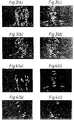
- the resulting representation images for these features are shown in Figures 2(a) to 2(d).
- the representation image of Figure 2(a) was thresholded to obtain an image bitmap as illustrated in Figure 3(a) which retained only those portions of the image appropriate feature type.
- the picture elements of the image bitmaps of different orientations of a given feature type were then compared and the maximum valued picture element only retained. That is the image bitmap containing the maximum valued picture element retained that pixel whereas the equivalent picture elements in the other image bitmaps with which it has been compared are deleted.
- This provides a series of image bitmaps for a given feature type without any overlap between the areas of activity for the various orientations of that feature type.
- the size of the individual areas of the image bitmap of Figure 3(a) were then sized by counting the number of picture elements in the particular feature. This gave a measure of the size of the feature which was then tested against a threshold. Those which were too small were deleted from the image bitmap to obtain the modified image bitmap of Figure 4(a).
- the areas of activity that remained in the modified image bitmap of Figure 4(a) were then detected as an occurrence of the feature type, all the other instances being ignored.
- the feature position was calculated by weight averaging the picture element constituents of the feature, ie the centroid of the feature, which position was considered to be the point of the image at which the feature was located. Associated with this feature was a token which represented the feature type and its position within the image.
- Any attributes that may be of interest according to the particular application to which the template is going to be put could also form part of the token.
- it could contain information about the size of the feature and its strength.
- the result of this processing was a series of tokens which characterised the feature type content of the original image.
- a set of tokens was obtained for the other feature types that were to be used in forming the final template.
- the full set of tokens for all the feature types was then constructed which set formed the basis of a template of the original image obtained by triangulating the feature type positions.
- FIG. 5 there is illustrated a template constructed by forming a structural mesh of links between the feature positions of all the tokenised feature types of Figures 4(a) to 4(d).
- the mesh was formed by connecting the feature positions with a triangulated mesh using Delauney triangulation of all the feature positions.
- the template so formed was the desired template representation of the original image.
- the photograph at Figure 5 shows the template superimposed on the original image with the feature positions being denoted by node positions which are linked by straight line segments.
- the different processed images will not be shown visually on a visual display unit during processing of an image to form a template, rather the steps of the invention will utilise stored representations of the training image and its processed forms.
- a template according to the present invention can be used to both recognise and describe the shape of novel instances of the object type upon which it has been trained by initialising it in the vicinity of an object in an image and allowing template feature types to be attracted to corresponding characteristics in the target image whilst at the same time deforming its geometric shape within limits according to how closely image detail can be matched.
- This fitting process is analogous to that used by traditional deformable templates of the type described by Yuille et al , referenced above.
- a template is to be suitable for fitting and so describes the shape of the majority of novel instances of a given object which may be subsequently encountered then it has been found by the Applicant, to be greatly beneficial that templates are formed from more than one image of different members of the class of object which is to be recognised and combining the templates to form a generalised template.
- This scheme which also constitutes an aspect of the present invention, provides a generalised template which incorporates the salient features appropriate to the class of object rather than the specific features for a particular member of the class. This provides a template which is more suitable for classifying objects as opposed to identifying a particular member of a class of objects where a template solely based on that one image will be preferable.
- the method of forming a generalised template presently preferred by the Applicant is to use a genetic algorithm to determine which of the template features are most valuable in recognising an object in the class on which it is trained.
- the basic algorithm requires a genetic representation analogous to the chromosomes in living creatures, a way of interpreting this representation to form a population member and a method of establishing the fitness of each population member.
- the algorithm itself starts with an initial, possibly poor or unfit, population and iteratively improves the fitness by preferentially selecting fit members to be the parents of the next generation' s members. Fitter members thus tend to contribute preferentially to the gene pool of the next generation, and it can be shown that genes which contribute to the above average fitness tend to increase exponentially in frequency from generation to generation.
- the power of genetic algorithms does not lie merely in the survival of the fittest strategy but also in the way in which the two population members are combined.
- the chromosomes from any two parents should both contribute to the chromosome of their children (usually two are produced) by means of crossover. This is a phenomenon observed in animal genetics in which two chromosomes align with one another and contiguous strands of genetic material are exchanged. Thus new combinations of genes from fitter population members are constantly being tried together to obtain an overall fitness improvement.
- the set of templates to be combined should be based on a set of training images which are representative of objects that are likely to be encountered in the future.
- the set of image characteristics described by the derived templates should contain all the relevant elements to describe the appearance of most new objects likely to be presented to an image recognising apparatus.
- the genetic algorithm is then applied to swap elements between chromosomes from generation to generation which has the effect of producing new chromosomes representing templates which contain new mixtures of elements taken from various different initial templates.
- a part of a template good at matching for example eyes in one template may be co-joined with a part of another template good at matching a mouth thereby producing a composite template good at doing both tasks.
- Each template that is going to contribute to the composite template must be encoded as a chromosomal representation for the genetic algorithm to operate upon.
- chromosomal representation of a template there must also be a method of interpreting chromosomes in order to derive the corresponding template individual.
- a method of interpreting chromosomes in order to derive the corresponding template individual.
- chromosome representation exhibits due to constraints laid down by genetic algorithms in general as well as practical considerations. It is preferable to have a fixed length chromosome description consisting of a fixed number of gene units as this helps during mating and crossover of chromosomes. Collections of genes which provide advantageous attributes in individuals are said to be co-adapted, that is they work well together. It is preferable that such co-adapted genes congregate locally on the chromosome such that they tend to be preserved during crossover. Each gene should preferably represent an element from an alphabet of low order, ie it should only be able to take on a small range of values.
- the chromosomes described to date in the scientific literature consist of linear strings of genes. Although a 2-D chromosomal representation may seem to be closer to the 2-D nature of the templates, the present embodiment uses the more traditional linear mapping of genes for which the theory is now reasonably well developed albeit in other applications. Alternative chromosome representation strategies may, of course, be adopted if they prove to be advantageous.
- the linear structure of the genes within a chromosome should not present any problems, however, since during initialisation the feature types which are in close proximity spatially are represented by genes close together on the chromosome.
- the property exhibited by genetic algorithms is to provide clustering of co-adapted genes on the chromosome which should help to prevent such clusters from being broken up during crossover.
- the image area was quantised into a fixed number of zones (square regions) Z i as shown in Figure 7.
- Each zone Z i could contain one or more instances of the recognisable feature types but only one was coded in the chromosome.
- Figure 8 shows the information encoded by a gene G i of a chromosome. It consisted of three gene fields, F 1 , F 2 and F 3 . Gene field F 1 contained the number of the zone Z i which it encodes - in this case zone number 34. Gene field F 2 contained a flag indicating whether the feature type within that zone is active. Gene field F 3 denoted the feature type - in this case a top right to bottom left, 45° edge.
- the genes G i contained a reference to the zone Z i of the image to which they corresponded the zone number Z i and the position of a gene on a chromosome were therefore independent so they could change their relative chromosome location freely, as desired.
- the genes were restricted to elements from a relatively low order alphabet consisting of the number of allowable feature types.
- zone Z i to which a gene G i corresponded was indicated by a zone number.
- the actual zone details such as zone position and adjacency information were held in a separate location in order to minimise the extraneous detail which had to be coded by each gene.
- a compact representation is more efficient which was important during implementation of the algorithm.
- the connectivity of the feature types within the template structural mesh was not encoded at all within the genetic representation but was created automatically during expression of the chromosome to produce the corresponding template as will be described below.
- genetic algorithms are often initialised randomly and then allowed to search for a solution, it is preferable to initialise the population from a set of base templates derived from a set of training images of the object of interest. It should be noted that these images were very crudely normalised such that the centres of the eye and mouth in each image also align across all the images in order to assist the genetic algorithm in combining templates during later stages.
- the first stage of initialisation was to convert the base templates into their equivalent chromosome representations. This consisted of determining within which zone each template feature type lay and then assigning a gene for that feature type. When more than one 9 feature type falls within a single zone, an arbitrary one was kept the rest being discarded. The only remaining variable in the initialisation was the ordering of the genes on the chromosome. Since it was not known at initialisation which feature types were related, and hence which genes were co-adapted, the optimal ordering of genes was not known. However, a strategy was adopted which located genes containing spatially close tokens in similar proximity on the chromosome as it had been found that local feature types are often related to one another.
- the strategy used in the present embodiment to decide which genes go where on the chromosome consisted of a recursive spatial subdivision process applied to the space of the entire image.
- a full image 62 was recursively split once, evenly, into four sub-regions S 1 to S 4 about the midpoint of the image, which sub-regions were then randomly ordered and split again until the sub-regions S ijk reached the specified zone size.
- the chromosomal description of an individual is known as the genotype and this can be expressed or interpreted to form the individual itself known as the phenotype. It is necessary to be able to express the chromosome in terms of the phenotype before one can go on to evaluate the fitness of the given individual.
- the phenotype consists of a template in the present instance.
- each gene G i of the chromosome was examined and if marked as active a corresponding feature type was created in the generalised template structure of the type specified by the field F 3 of the gene G i .
- the gene G i also implicitly codes the position of the feature type in terms of the zone index which could be cross referenced to the list of zone details to provide the feature position information.
- the template nodes had to be triangulated as previously described to form the template and for fitting to a given test image.
- the triangulation was performed as a post-processing stage just prior to fitting the template.
- No node connectivity information was encoded within the genetic representation itself.
- a trivial solution for obtaining a maximal fit and image response is a template which saturates a test image with all possible, feature types to be matched. Since it is also required that a template description is as concise as possible, that is without an instances excess of feature types, a cost is associated with the template which increases with increasing numbers of occurrences of feature types and so prevents oversaturation of template nodes.
- the final template had to work well for most of the novel faces likely to be encountered so it was necessary to assess the template' s merit measure against a range of faces.
- An environment of face images was therefore used which is separate from the initial training set.
- To evaluate each member of the population at a given generation a sample of test face images was randomly picked from the environment set.
- Each individual template was then fitted to each of the test set of images using a small number of iterations on the above measure of merit and a single average merit value calculated per template. These values formed the final unnormalised measures of merit for each template.
- the merit value G described above includes both negative and positive values. It is necessary to form a measure of fitness for use by the genetic algorithm which is both non-negative and exhibits an even spread of values across the population during any given generation so the better members can be effectively discriminated for.
- the measure G was normalised to achieve these criteria and yield a fitness value that was useable.
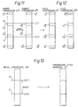
- Crossover is the most powerful of the genetic operators employed in this genetic algorithm and will now be explained with references to Figures 11 and 12.
- Crossover provides the means for useful attributes of one individual to combine with other useful attributes from a second individual to produce a child which hopefully exhibits the strengths of both. Many combinations are tried together with poor combinations being weeded out by fitness selection. Crossover was applied with a high probability of about 0. 6.
- two cut points 70 and 71 were randomly chosen using a uniform probability distribution over the length of two chromosomes G A and G B having gene strings G A 1 to G A n and G B 1 to G B n , respectively.
- the cut points 70 and 71 define two regions of the parent chromosomes G A c to G A d and G B c to G B d , respectively. These were exchanged to create two children chromosomes G C and G D as shown in Figure 12.
- a further technique employed in the genetic algorithm of the present invention was mutation, a genetic operator which acts on a single gene to randomly change it in some way.
- the mutation operation was applied with a very low probability as a background operator to the algorithm as a whole, its function being to reintroduce genetic variation which may have been lost, or new useful variations.
- the principal mechanisms of this genetic algorithm is the combination of the crossover operator and the survival of the fittest selection.
- n log(1-c/log(1-p))
- the activity of the gene and hence the corresponding token was toggled. If the gene was active and so contained a token it was marked inactive, otherwise it was marked active and the corresponding feature type field F 3 assigned a random feature type from those allowable. As there was a gene for every zone within an image, a feature type could, potentially, have become active with any zone Z i at any of the available image locations.
- the inversion operator was a further type of mutation operator also included in the algorithm of the present invention which operated at a fairly low probability. It operates on a single chromosome and its affect is to completely invert the sequence order of a randomly chosen string of genes on the chromosome as shown in Figure 13.
- the gene string of a chromosome G E to be inverted is chosen by randomly selecting two end points 72, 73 based on the uniform probability function over the entire length of the chromosome. This gene string is then reversed in order within the chromosome G E to form a new chromosome G F .
- inversion does not affect the template corresponding to the chromosome during the current generation as the same tokens are coded regardless of the gene order.
- the main effect of inversion is to allow genes to change position on the chromosome such that co-adapted genes tend to become clustered over time. Such clusters of genes will tend to be preserved during crossover as the cut point is less likely to fall between co-adapted genes if they are physically close on the chromosome.
- genes coding for feature types good at matching an eye may cluster and then usefully propagate through the population and eventually be combined with a similar co-adapted gene cluster relevant to matching a mouth to thereby improve the template as a whole.
- the algorithm described above was carried out on a Meiko transputer array consisting of an array of 64 individual transputer based processing nodes and some special nodes consisting of graphics display cards.
- the actual implementation of the algorithm described above is arbitrary to the extent that it only affects the time taken to compute the generalised template from the set of individual templates.
Landscapes
- Engineering & Computer Science (AREA)
- Theoretical Computer Science (AREA)
- Physics & Mathematics (AREA)
- Data Mining & Analysis (AREA)
- General Physics & Mathematics (AREA)
- Bioinformatics & Cheminformatics (AREA)
- Life Sciences & Earth Sciences (AREA)
- Evolutionary Biology (AREA)
- Evolutionary Computation (AREA)
- Bioinformatics & Computational Biology (AREA)
- General Engineering & Computer Science (AREA)
- Artificial Intelligence (AREA)
- Computer Vision & Pattern Recognition (AREA)
- Health & Medical Sciences (AREA)
- General Health & Medical Sciences (AREA)
- Oral & Maxillofacial Surgery (AREA)
- Human Computer Interaction (AREA)
- Multimedia (AREA)
- Image Analysis (AREA)
Claims (10)
- Verfahren zum Erzeugen einer Schablone eines ersten Bildes für den nachfolgenden Vergleich mit einem zweiten Bild, das umfaßt:Erfassen von Auftritten von einem oder mehreren in dem ersten Bild vorhandenen, im voraus definierten Bildmerkmalstypen;Zuordnen eines Ortes innerhalb des ersten Bildes zu jedem solchen Auftreten;Zuordnen eines Schablonenknotens zu jedem solchen Ort;für jeden solchen Auftritt Zuordnen des Auftrittsmerkmalstyps zu dem dem Auftrittsort zugeordneten Knoten; undZuordnen von Schablonenverknüpfungen zu Schablonenknoten, um so eine Schablone des ersten Bildes zu erzeugen.
- Verfahren nach Anspruch 1, das ferner für jeden erfaßten Auftritt das Zuordnen weiterer Auftrittsdaten zu dem Knoten, der dem Auftrittsort zugeordnet ist, umfaßt.
- Verfahren nach Anspruch 1 oder Anspruch 2, bei dem der Schritt des Zuordnens von Schablonenverknüpfungen zu Schablonenknoten die Verwendung der Delauney-Triangulation umfaßt.
- Verfahren zum Erzeugen eines Ähnlichkeitsmaßes zwischen einer Schablone eines ersten Bildes und einem zweiten Bild, bei dem die Schablone gemäß einem vorhergehenden Anspruch einschließlich der Erfassung des Auftritts von einem oder mehreren im ersten Bild vorhandenen, im voraus definierten Bildmerkmalstypen erzeugt wird, wobei das Verfahren umfaßt:Erfassen von Auftritten von einem oder mehreren in dem zweiten Bild vorhandenen, im voraus definierten Bildmerkmalstypen;Verformen der Schablone des ersten Bildes in Abhängigkeit von einer im voraus definierten Energiefunktion, um eine verformte Schablone zu erzeugen, derart, daß die Schablonenknoten zu den Auftritten ihrer jeweiligen zugeordneten Merkmalstypen angezogen werden, während die Schablonenverknüpfungen die Schablonenverformung einschränken; undErzeugen eines Ähnlichkeitsmaßes zwischen der Schablone des ersten Bildes und dem zweiten Bild in Abhängigkeit von der Differenz der Energiezustände, die der Schablone des ersten Bildes und der verformten Schablone zugeordnet sind.
- Verfahren zur Bilderkennung, das umfaßt:Erzeugen eines Ähnlichkeitsmaßes zwischen einer Schablone eines ersten Bildes und einem zweiten Bild nach Anspruch 4; undVeranlassen, daß das zweite Bild als eine Instanz des ersten Bildes erkannt wird, falls das Ähnlichkeitsmaß einen im voraus definierten Schwellenwert übersteigt.
- Verfahren zum Erzeugen einer Schablone einer Menge von Bildern für den nachfolgenden Vergleich mit einem weiteren Bild, das die folgenden Schritte umfaßt:(a) Erzeugen einer Schablone für jedes Trainingsbild einer Trainingsbildmenge gemäß dem Verfahren nach Anspruch 1;(b) Erzeugen eines Datensatzes, der jeder solchen Schablone entspricht; wobei jeder Datensatz eine lineare Reihe von Einträgen besitzt, wobei jeder Eintrag einem der Knoten der jeweiligen Schablonen entspricht und wenigstens einen zugeordneten Knotenmerkmalstyp und eine zugeordnete Knotenadresse repräsentiert;(c) Erzeugen einer Schablone, die jedem Datensatz entspricht; Verwenden jedes Eintrags, um einen entsprechenden Schablonenknoten des zugeordneten Merkmalstyps zu erzeugen, der sich an einem Schablonenort, der der zugeordneten Adresse entspricht, befindet; und Zuordnen von Schablonenverknüpfungen zu Schablonenknoten, um jede Schablone zu erzeugen;(d) Zuordnen eines Gütemaßes zu jeder Schablone für jedes Bild der Bildmenge;(e) Zuordnen eines Paßmaßes zu jeder Schablone für die Bildmenge in Abhängigkeit von den im Schritt (d) erzeugten Gütemaßen;(f) Auswählen einer Untermenge der Datensätze in Abhängigkeit vom Paßmaß ihrer im Schritt (e) erzeugten zugeordneten Schablonen; und(g) Anwenden genetischer Operatoren wenigstens auf die Untermenge, um neue Datensätze zu erzeugen.
- Verfahren nach Anspruch 6, bei dem die Datensatzeinträge, die Knoten entsprechen, denen Auftritte von in einem Bild nahe beieinander liegenden Bildmerkmalstypen zugeordnet sind, in der entsprechenden linearen Reihe nahe beieinander angeordnet sind.
- Schablonenerzeugungsvorrichtung zum Erzeugen einer Schablone eines ersten Bildes für den nachfolgenden Vergleich mit einem zweiten Bild, die umfaßt:Mittel, die so beschaffen sind, daß sie Auftritte eines oder mehrerer in dem ersten Bild vorhandener, im voraus definierter Bildmerkmalstypen erfassen;Mittel, die so beschaffen sind, daß sie jedem Auftritt in dem Bild einen Ort zuordnen;Mittel, die so beschaffen sind, daß sie jedem Ort, dem ein Auftritt zugeordnet ist, einen Schablonenknoten zuordnen;Mittel, die so beschaffen sind, daß sie für jeden Auftritt den Auftrittsmerkmalstyp dem dem Auftrittsort zugeordneten Knoten zuordnen; undMittel, die so beschaffen sind, daß sie den Schablonenknoten Schablonenverknüpfungen zuordnen, um eine Schablone des ersten Bildes zu erzeugen.
- Bilderkennungsvorrichtung, die umfaßt:Mittel, die so beschaffen sind, daß sie eine Schablone eines ersten Bildes speichern, wobei die Schablone gemäß einem der Ansprüche 1-3 erzeugt wird, umfassend das Erfassen von Auftritten von einem oder mehreren in dem ersten Bild vorhandenen, im voraus definierten Bildmerkmalstypen;Mittel, die so beschaffen sind, daß sie Auftritte des einen oder der mehreren in dem zweiten Bild vorhandenen, im voraus definierten Bildmerkmalstypen erfassen;Mittel, die so beschaffen sind, daß sie die Schablone des ersten Bildes in Abhängigkeit von einer im voraus definierten Energiefunktion verformen, um eine verformte Schablone zu erzeugen, derart, daß die Schablonenknoten zu Auftritten ihrer jeweiligen zugeordneten Merkmalstypen angezogen werden, während die Schablonenverknüpfungen Schablonenverformungen begrenzen; undMittel, die so beschaffen sind, daß sie ein Ähnlichkeitsmaß zwischen der Schablone des ersten Bildes und dem zweiten Bild in Abhängigkeit von der Differenz der Energiezustände, die der Schablone des ersten Bildes und der verformten Schablone zugeordnet sind, aufbauen; undMittel, die so beschaffen sind, daß sie veranlassen, daß das zweite Bild als eine Instanz des ersten Bildes erkannt wird, falls das Ähnlichkeitsmaß einen im voraus definierten Schwellenwert übersteigt.
- Schablonenerzeugungsvorrichtung zum Erzeugen einer Schablone einer Menge von Bildern für den nachfolgenden Vergleich mit einem weiteren Bild, die umfaßt:Mittel, die so beschaffen sind, daß sie Schablonen jedes Trainingsbildes einer Trainingsbildmenge speichern, wobei jede Schablone gemäß einem der Ansprüche 1-3 einschließlich der Erfassung von Auftritten von einem oder mehreren in dem ersten Bild vorhandenen, im voraus definierten Bildmerkmalstypen erzeugt wird;Mittel, die so beschaffen sind, daß sie eine Menge von Datensätzen erzeugen; wobei jeder Datensatz einer Schablone entspricht; wobei jeder Datensatz eine lineare Reihe von Einträgen besitzt, wobei jeder Eintrag einem der Knoten der jeweiligen Schablone entspricht und wenigstens einen zugeordneten Knotenmerkmalstyp und eine zugeordnete Knotenadresse repräsentiert;Mittel, die so beschaffen sind, daß sie eine Schablone erzeugen, die jedem Datensatz entspricht, wobei jeder Eintrag verwendet wird, um einen entsprechenden Schablonenknoten des zugeordneten Merkmalstyps zu erzeugen, der sich an einem Schablonenort befindet, der der zugeordneten Adresse entspricht; und wobei Schablonenverknüpfungen zu Schablonenknoten zugeordnet werden, um jede Schablone zu erzeugen;Mittel, die so beschaffen sind, daß sie jeder Schablone ein Gütemaß für jedes Bild der Menge von Bildern zuordnen;Mittel, die so beschaffen sind, daß sie einer Schablone ein Paßmaß für die Bildmenge in Abhängigkeit vom zugeordneten Gütemaß zuordnen;Mittel, die so beschaffen sind, daß sie eine Untermenge von Datensätzen in Abhängigkeit vom Paßmaß ihrer entsprechenden Schablonen auswählen; undMittel, die so beschaffen sind, daß sie genetische Operatoren wenigstens auf die ausgewählte Untermenge anwenden, um eine neue Menge von Datensätzen zu erzeugen.
Applications Claiming Priority (3)
| Application Number | Priority Date | Filing Date | Title |
|---|---|---|---|
| GB929201856A GB9201856D0 (en) | 1992-01-29 | 1992-01-29 | Method of forming a template |
| GB9201856 | 1992-01-29 | ||
| PCT/GB1993/000179 WO1993015475A1 (en) | 1992-01-29 | 1993-01-28 | Method of forming a template |
Publications (2)
| Publication Number | Publication Date |
|---|---|
| EP0628190A1 EP0628190A1 (de) | 1994-12-14 |
| EP0628190B1 true EP0628190B1 (de) | 2002-09-04 |
Family
ID=10709435
Family Applications (1)
| Application Number | Title | Priority Date | Filing Date |
|---|---|---|---|
| EP93902475A Expired - Lifetime EP0628190B1 (de) | 1992-01-29 | 1993-01-28 | Verfahren zur maskenerzeugung |
Country Status (8)
| Country | Link |
|---|---|
| US (1) | US5978507A (de) |
| EP (1) | EP0628190B1 (de) |
| JP (1) | JPH07507168A (de) |
| CA (1) | CA2128885C (de) |
| DE (1) | DE69332265T2 (de) |
| GB (1) | GB9201856D0 (de) |
| SG (1) | SG49099A1 (de) |
| WO (1) | WO1993015475A1 (de) |
Families Citing this family (42)
| Publication number | Priority date | Publication date | Assignee | Title |
|---|---|---|---|---|
| DE4406020C1 (de) * | 1994-02-24 | 1995-06-29 | Zentrum Fuer Neuroinformatik G | Verfahren zur automatisierten Erkennung von Objekten |
| JP2603445B2 (ja) * | 1994-11-10 | 1997-04-23 | インターナショナル・ビジネス・マシーンズ・コーポレイション | 髪画像適合方法及びコンピュータ・システム |
| US6226418B1 (en) * | 1997-11-07 | 2001-05-01 | Washington University | Rapid convolution based large deformation image matching via landmark and volume imagery |
| JP3577207B2 (ja) * | 1996-12-12 | 2004-10-13 | 富士通株式会社 | 遺伝的アルゴリズム実行装置、実行方法およびそのプログラム記憶媒体 |
| SE511514C2 (sv) * | 1997-05-13 | 1999-10-11 | Ericsson Telefon Ab L M | Förfarande och anordning för bildkompression |
| JP2000172852A (ja) * | 1998-09-28 | 2000-06-23 | Canon Inc | 画像処理方法、装置および記録媒体 |
| US6633686B1 (en) | 1998-11-05 | 2003-10-14 | Washington University | Method and apparatus for image registration using large deformation diffeomorphisms on a sphere |
| US6791572B1 (en) * | 1999-06-18 | 2004-09-14 | Phoenix Technologies Ltd. | Generating media output during BIOS boot-up |
| TW445434B (en) * | 1999-08-04 | 2001-07-11 | Cyberlink Corp | System and method for automatically extracting facial features |
| US6801653B1 (en) * | 1999-08-05 | 2004-10-05 | Sony Corporation | Information processing apparatus and method as well as medium |
| US6658299B1 (en) * | 2000-01-04 | 2003-12-02 | William H. Dobelle | Artificial system for vision and the like |
| US6539354B1 (en) | 2000-03-24 | 2003-03-25 | Fluent Speech Technologies, Inc. | Methods and devices for producing and using synthetic visual speech based on natural coarticulation |
| WO2002019137A1 (en) * | 2000-08-29 | 2002-03-07 | Imageid Ltd. | Indexing, storage & retrieval of digital images |
| EP1360833A1 (de) | 2000-08-31 | 2003-11-12 | Rytec Corporation | Sensor und abbildungssystem |
| US7079158B2 (en) * | 2000-08-31 | 2006-07-18 | Beautyriot.Com, Inc. | Virtual makeover system and method |
| US6542638B2 (en) * | 2001-02-21 | 2003-04-01 | Shannon Roy Campbell | Method for matching spatial patterns |
| KR100456619B1 (ko) * | 2001-12-05 | 2004-11-10 | 한국전자통신연구원 | 에스.브이.엠(svm)을 이용한 얼굴 등록/인증 시스템 및방법 |
| US7116823B2 (en) * | 2002-07-10 | 2006-10-03 | Northrop Grumman Corporation | System and method for analyzing a contour of an image by applying a Sobel operator thereto |
| US7146057B2 (en) * | 2002-07-10 | 2006-12-05 | Northrop Grumman Corporation | System and method for image analysis using a chaincode |
| US7149356B2 (en) * | 2002-07-10 | 2006-12-12 | Northrop Grumman Corporation | System and method for template matching of candidates within a two-dimensional image |
| WO2004023787A2 (en) | 2002-09-06 | 2004-03-18 | Rytec Corporation | Signal intensity range transformation apparatus and method |
| CA2509644A1 (en) | 2002-12-11 | 2004-06-24 | Nielsen Media Research, Inc. | Detecting a composition of an audience |
| US7203338B2 (en) * | 2002-12-11 | 2007-04-10 | Nielsen Media Research, Inc. | Methods and apparatus to count people appearing in an image |
| EP1611546B1 (de) | 2003-04-04 | 2013-01-02 | Icosystem Corporation | Verfahren und systeme zur interaktiven evolutionären datenverarbeitung (iec) |
| WO2005013081A2 (en) * | 2003-08-01 | 2005-02-10 | Icosystem Corporation | Methods and systems for applying genetic operators to determine system conditions |
| US7356518B2 (en) | 2003-08-27 | 2008-04-08 | Icosystem Corporation | Methods and systems for multi-participant interactive evolutionary computing |
| AU2004277166A1 (en) * | 2003-09-22 | 2005-04-07 | Kim Hyeung-Yun | Sensors and systems for structural health monitoring |
| JP4847685B2 (ja) * | 2004-04-16 | 2011-12-28 | 株式会社日立ハイテクノロジーズ | パターンサーチ方法 |
| US7707220B2 (en) | 2004-07-06 | 2010-04-27 | Icosystem Corporation | Methods and apparatus for interactive searching techniques |
| WO2007035848A2 (en) | 2005-09-21 | 2007-03-29 | Icosystem Corporation | System and method for aiding product design and quantifying acceptance |
| US7792816B2 (en) | 2007-02-01 | 2010-09-07 | Icosystem Corporation | Method and system for fast, generic, online and offline, multi-source text analysis and visualization |
| US7940985B2 (en) * | 2007-06-06 | 2011-05-10 | Microsoft Corporation | Salient object detection |
| US8411963B2 (en) | 2008-08-08 | 2013-04-02 | The Nielsen Company (U.S.), Llc | Methods and apparatus to count persons in a monitored environment |
| US8971413B2 (en) * | 2010-05-24 | 2015-03-03 | Intel Corporation | Techniques for storing and retrieving pixel data |
| US8620088B2 (en) | 2011-08-31 | 2013-12-31 | The Nielsen Company (Us), Llc | Methods and apparatus to count people in images |
| US9128030B1 (en) * | 2013-03-06 | 2015-09-08 | The Boeing Company | X-ray backscattering battery inspection |
| US12118729B2 (en) * | 2020-05-11 | 2024-10-15 | Nec Corporation | Determination device, determination method, and recording medium |
| US11711638B2 (en) | 2020-06-29 | 2023-07-25 | The Nielsen Company (Us), Llc | Audience monitoring systems and related methods |
| US12356286B2 (en) | 2021-07-22 | 2025-07-08 | The Nielsen Company (Us), Llc | Methods, apparatus, and articles of manufacture to locate persons based on adjustable signal strength thresholds |
| US11860704B2 (en) | 2021-08-16 | 2024-01-02 | The Nielsen Company (Us), Llc | Methods and apparatus to determine user presence |
| US11758223B2 (en) | 2021-12-23 | 2023-09-12 | The Nielsen Company (Us), Llc | Apparatus, systems, and methods for user presence detection for audience monitoring |
| US12088882B2 (en) | 2022-08-26 | 2024-09-10 | The Nielsen Company (Us), Llc | Systems, apparatus, and related methods to estimate audience exposure based on engagement level |
Family Cites Families (5)
| Publication number | Priority date | Publication date | Assignee | Title |
|---|---|---|---|---|
| SE365325B (de) * | 1971-11-04 | 1974-03-18 | Rothfjell R | |
| JP2710062B2 (ja) * | 1988-11-29 | 1998-02-10 | 日本電気セキュリティシステム株式会社 | 出力候補数決定方式 |
| WO1991014990A1 (en) * | 1990-03-28 | 1991-10-03 | Koza John R | Non-linear genetic algorithms for solving problems by finding a fit composition of functions |
| US5164992A (en) * | 1990-11-01 | 1992-11-17 | Massachusetts Institute Of Technology | Face recognition system |
| US5359526A (en) * | 1993-02-04 | 1994-10-25 | Hughes Training, Inc. | Terrain and culture generation system and method |
-
1992
- 1992-01-29 GB GB929201856A patent/GB9201856D0/en active Pending
-
1993
- 1993-01-28 US US08/256,835 patent/US5978507A/en not_active Expired - Lifetime
- 1993-01-28 DE DE69332265T patent/DE69332265T2/de not_active Expired - Lifetime
- 1993-01-28 EP EP93902475A patent/EP0628190B1/de not_active Expired - Lifetime
- 1993-01-28 SG SG1996005997A patent/SG49099A1/en unknown
- 1993-01-28 CA CA002128885A patent/CA2128885C/en not_active Expired - Lifetime
- 1993-01-28 WO PCT/GB1993/000179 patent/WO1993015475A1/en not_active Ceased
- 1993-01-28 JP JP5513052A patent/JPH07507168A/ja active Pending
Non-Patent Citations (1)
| Title |
|---|
| Inexact graph matching used in machine vison, Devijver and Kittler, Pattern Recognition Theory and Applications, nato ASI Series Vol. F30, Springer, 1987, pp 347-356. * |
Also Published As
| Publication number | Publication date |
|---|---|
| SG49099A1 (en) | 1998-05-18 |
| US5978507A (en) | 1999-11-02 |
| DE69332265T2 (de) | 2003-04-17 |
| JPH07507168A (ja) | 1995-08-03 |
| WO1993015475A1 (en) | 1993-08-05 |
| GB9201856D0 (en) | 1992-03-18 |
| CA2128885A1 (en) | 1993-08-05 |
| CA2128885C (en) | 1999-05-04 |
| EP0628190A1 (de) | 1994-12-14 |
| DE69332265D1 (de) | 2002-10-10 |
Similar Documents
| Publication | Publication Date | Title |
|---|---|---|
| US5978507A (en) | Method of forming a template of an image of an object for use in the recognition of the object | |
| CN112784763A (zh) | 基于局部与整体特征自适应融合的表情识别方法及系统 | |
| CN108491773A (zh) | 一种识别方法及系统 | |
| JP2021528728A (ja) | 疑似画像を使用した顔画像認識 | |
| CN114419391B (zh) | 目标图像识别方法及装置、电子设备及可读存储介质 | |
| CN113205002A (zh) | 非受限视频监控的低清人脸识别方法、装置、设备及介质 | |
| CN109522824A (zh) | 人脸属性识别方法、装置、计算机装置及存储介质 | |
| Tian et al. | Genetic algorithm based deep learning model selection for visual data classification | |
| Thepade et al. | Enhanced face presentation attack prevention employing feature fusion of pretrained deep convolutional neural network model and thepade's sorted block truncation coding | |
| CN116865994A (zh) | 一种基于大数据的网络数据安全预测方法 | |
| Pandey et al. | A hierarchical clustering approach for image datasets | |
| CN115146093A (zh) | 图像检索方法、电子设备和计算机可读存储介质 | |
| Pillai et al. | Classification of Endangered Species of Wild Cats through Xception Transfer Learning Model | |
| CN109034109B (zh) | 一种基于聚类算法的行人重识别方法和装置 | |
| CN116483932B (zh) | 一种基于心内科冠心病药物库的分级分类管理方法和装置 | |
| CN114495151B (zh) | 一种群组行为识别方法 | |
| Mitchell et al. | Spatially Biased Random Forests. | |
| Das et al. | Content based image recognition by Information fusion with multiview features | |
| Maaz et al. | Influencing factors in facial recognition and verification: A siamese neural network hyperparameter study | |
| Ghorpade et al. | Neural Networks for face recognition Using SOM | |
| CN114154002A (zh) | 图像检索方法、图像检索系统、电子设备和存储介质 | |
| CN113033499A (zh) | 虹膜识别方法和装置 | |
| Ligade et al. | Content Based Image Retrieval Using Interactive Genetic Algorithm with Relevance Feedback Technique—Survey | |
| Fauziah et al. | Classification Using Feature Extraction of Leaf Based on Neural Network Algorithm with K Nearest Neighbor and Supervised Learning | |
| Agrawal et al. | Gender, Age and Ethnicity Detection |
Legal Events
| Date | Code | Title | Description |
|---|---|---|---|
| PUAI | Public reference made under article 153(3) epc to a published international application that has entered the european phase |
Free format text: ORIGINAL CODE: 0009012 |
|
| 17P | Request for examination filed |
Effective date: 19940803 |
|
| AK | Designated contracting states |
Kind code of ref document: A1 Designated state(s): DE ES FR GB IT NL SE |
|
| 17Q | First examination report despatched |
Effective date: 19980720 |
|
| GRAG | Despatch of communication of intention to grant |
Free format text: ORIGINAL CODE: EPIDOS AGRA |
|
| GRAG | Despatch of communication of intention to grant |
Free format text: ORIGINAL CODE: EPIDOS AGRA |
|
| GRAH | Despatch of communication of intention to grant a patent |
Free format text: ORIGINAL CODE: EPIDOS IGRA |
|
| GRAH | Despatch of communication of intention to grant a patent |
Free format text: ORIGINAL CODE: EPIDOS IGRA |
|
| GRAA | (expected) grant |
Free format text: ORIGINAL CODE: 0009210 |
|
| AK | Designated contracting states |
Kind code of ref document: B1 Designated state(s): DE ES FR GB IT NL SE |
|
| PG25 | Lapsed in a contracting state [announced via postgrant information from national office to epo] |
Ref country code: NL Free format text: LAPSE BECAUSE OF FAILURE TO SUBMIT A TRANSLATION OF THE DESCRIPTION OR TO PAY THE FEE WITHIN THE PRESCRIBED TIME-LIMIT Effective date: 20020904 Ref country code: IT Free format text: LAPSE BECAUSE OF FAILURE TO SUBMIT A TRANSLATION OF THE DESCRIPTION OR TO PAY THE FEE WITHIN THE PRE;WARNING: LAPSES OF ITALIAN PATENTS WITH EFFECTIVE DATE BEFORE 2007 MAY HAVE OCCURRED AT ANY TIME BEFORE 2007. THE CORRECT EFFECTIVE DATE MAY BE DIFFERENT FROM THE ONE RECORDED.SCRIBED TIME-LIMIT Effective date: 20020904 |
|
| REG | Reference to a national code |
Ref country code: GB Ref legal event code: FG4D |
|
| REF | Corresponds to: |
Ref document number: 69332265 Country of ref document: DE Date of ref document: 20021010 |
|
| PG25 | Lapsed in a contracting state [announced via postgrant information from national office to epo] |
Ref country code: SE Free format text: LAPSE BECAUSE OF FAILURE TO SUBMIT A TRANSLATION OF THE DESCRIPTION OR TO PAY THE FEE WITHIN THE PRESCRIBED TIME-LIMIT Effective date: 20021204 |
|
| NLV1 | Nl: lapsed or annulled due to failure to fulfill the requirements of art. 29p and 29m of the patents act | ||
| ET | Fr: translation filed | ||
| PG25 | Lapsed in a contracting state [announced via postgrant information from national office to epo] |
Ref country code: ES Free format text: LAPSE BECAUSE OF FAILURE TO SUBMIT A TRANSLATION OF THE DESCRIPTION OR TO PAY THE FEE WITHIN THE PRESCRIBED TIME-LIMIT Effective date: 20030328 |
|
| PLBE | No opposition filed within time limit |
Free format text: ORIGINAL CODE: 0009261 |
|
| STAA | Information on the status of an ep patent application or granted ep patent |
Free format text: STATUS: NO OPPOSITION FILED WITHIN TIME LIMIT |
|
| 26N | No opposition filed |
Effective date: 20030605 |
|
| PGFP | Annual fee paid to national office [announced via postgrant information from national office to epo] |
Ref country code: FR Payment date: 20120206 Year of fee payment: 20 |
|
| PGFP | Annual fee paid to national office [announced via postgrant information from national office to epo] |
Ref country code: DE Payment date: 20120123 Year of fee payment: 20 |
|
| PGFP | Annual fee paid to national office [announced via postgrant information from national office to epo] |
Ref country code: GB Payment date: 20120120 Year of fee payment: 20 |
|
| REG | Reference to a national code |
Ref country code: DE Ref legal event code: R071 Ref document number: 69332265 Country of ref document: DE |
|
| REG | Reference to a national code |
Ref country code: DE Ref legal event code: R071 Ref document number: 69332265 Country of ref document: DE |
|
| REG | Reference to a national code |
Ref country code: GB Ref legal event code: PE20 Expiry date: 20130127 |
|
| PG25 | Lapsed in a contracting state [announced via postgrant information from national office to epo] |
Ref country code: GB Free format text: LAPSE BECAUSE OF EXPIRATION OF PROTECTION Effective date: 20130127 Ref country code: DE Free format text: LAPSE BECAUSE OF EXPIRATION OF PROTECTION Effective date: 20130129 |