EP0627779A1 - Sealed type nickel-metal hydride alkaline storage cell - Google Patents
Sealed type nickel-metal hydride alkaline storage cell Download PDFInfo
- Publication number
- EP0627779A1 EP0627779A1 EP94303896A EP94303896A EP0627779A1 EP 0627779 A1 EP0627779 A1 EP 0627779A1 EP 94303896 A EP94303896 A EP 94303896A EP 94303896 A EP94303896 A EP 94303896A EP 0627779 A1 EP0627779 A1 EP 0627779A1
- Authority
- EP
- European Patent Office
- Prior art keywords
- cell
- separator
- electrolyte
- metal hydride
- sealed type
- Prior art date
- Legal status (The legal status is an assumption and is not a legal conclusion. Google has not performed a legal analysis and makes no representation as to the accuracy of the status listed.)
- Granted
Links
Images



Classifications
-
- H—ELECTRICITY
- H01—ELECTRIC ELEMENTS
- H01M—PROCESSES OR MEANS, e.g. BATTERIES, FOR THE DIRECT CONVERSION OF CHEMICAL ENERGY INTO ELECTRICAL ENERGY
- H01M4/00—Electrodes
- H01M4/02—Electrodes composed of, or comprising, active material
- H01M4/36—Selection of substances as active materials, active masses, active liquids
- H01M4/38—Selection of substances as active materials, active masses, active liquids of elements or alloys
- H01M4/383—Hydrogen absorbing alloys
-
- H—ELECTRICITY
- H01—ELECTRIC ELEMENTS
- H01M—PROCESSES OR MEANS, e.g. BATTERIES, FOR THE DIRECT CONVERSION OF CHEMICAL ENERGY INTO ELECTRICAL ENERGY
- H01M10/00—Secondary cells; Manufacture thereof
- H01M10/24—Alkaline accumulators
- H01M10/30—Nickel accumulators
-
- H—ELECTRICITY
- H01—ELECTRIC ELEMENTS
- H01M—PROCESSES OR MEANS, e.g. BATTERIES, FOR THE DIRECT CONVERSION OF CHEMICAL ENERGY INTO ELECTRICAL ENERGY
- H01M50/00—Constructional details or processes of manufacture of the non-active parts of electrochemical cells other than fuel cells, e.g. hybrid cells
- H01M50/40—Separators; Membranes; Diaphragms; Spacing elements inside cells
- H01M50/409—Separators, membranes or diaphragms characterised by the material
- H01M50/411—Organic material
- H01M50/414—Synthetic resins, e.g. thermoplastics or thermosetting resins
- H01M50/417—Polyolefins
-
- H—ELECTRICITY
- H01—ELECTRIC ELEMENTS
- H01M—PROCESSES OR MEANS, e.g. BATTERIES, FOR THE DIRECT CONVERSION OF CHEMICAL ENERGY INTO ELECTRICAL ENERGY
- H01M10/00—Secondary cells; Manufacture thereof
- H01M10/34—Gastight accumulators
- H01M10/345—Gastight metal hydride accumulators
-
- H—ELECTRICITY
- H01—ELECTRIC ELEMENTS
- H01M—PROCESSES OR MEANS, e.g. BATTERIES, FOR THE DIRECT CONVERSION OF CHEMICAL ENERGY INTO ELECTRICAL ENERGY
- H01M4/00—Electrodes
- H01M4/02—Electrodes composed of, or comprising, active material
- H01M4/36—Selection of substances as active materials, active masses, active liquids
- H01M4/48—Selection of substances as active materials, active masses, active liquids of inorganic oxides or hydroxides
- H01M4/52—Selection of substances as active materials, active masses, active liquids of inorganic oxides or hydroxides of nickel, cobalt or iron
-
- H—ELECTRICITY
- H01—ELECTRIC ELEMENTS
- H01M—PROCESSES OR MEANS, e.g. BATTERIES, FOR THE DIRECT CONVERSION OF CHEMICAL ENERGY INTO ELECTRICAL ENERGY
- H01M50/00—Constructional details or processes of manufacture of the non-active parts of electrochemical cells other than fuel cells, e.g. hybrid cells
- H01M50/30—Arrangements for facilitating escape of gases
- H01M50/317—Re-sealable arrangements
- H01M50/325—Re-sealable arrangements comprising deformable valve members, e.g. elastic or flexible valve members
-
- H—ELECTRICITY
- H01—ELECTRIC ELEMENTS
- H01M—PROCESSES OR MEANS, e.g. BATTERIES, FOR THE DIRECT CONVERSION OF CHEMICAL ENERGY INTO ELECTRICAL ENERGY
- H01M50/00—Constructional details or processes of manufacture of the non-active parts of electrochemical cells other than fuel cells, e.g. hybrid cells
- H01M50/30—Arrangements for facilitating escape of gases
- H01M50/317—Re-sealable arrangements
- H01M50/325—Re-sealable arrangements comprising deformable valve members, e.g. elastic or flexible valve members
- H01M50/333—Spring-loaded vent valves
-
- H—ELECTRICITY
- H01—ELECTRIC ELEMENTS
- H01M—PROCESSES OR MEANS, e.g. BATTERIES, FOR THE DIRECT CONVERSION OF CHEMICAL ENERGY INTO ELECTRICAL ENERGY
- H01M50/00—Constructional details or processes of manufacture of the non-active parts of electrochemical cells other than fuel cells, e.g. hybrid cells
- H01M50/40—Separators; Membranes; Diaphragms; Spacing elements inside cells
- H01M50/409—Separators, membranes or diaphragms characterised by the material
- H01M50/44—Fibrous material
-
- H—ELECTRICITY
- H01—ELECTRIC ELEMENTS
- H01M—PROCESSES OR MEANS, e.g. BATTERIES, FOR THE DIRECT CONVERSION OF CHEMICAL ENERGY INTO ELECTRICAL ENERGY
- H01M2300/00—Electrolytes
- H01M2300/0002—Aqueous electrolytes
- H01M2300/0014—Alkaline electrolytes
-
- Y—GENERAL TAGGING OF NEW TECHNOLOGICAL DEVELOPMENTS; GENERAL TAGGING OF CROSS-SECTIONAL TECHNOLOGIES SPANNING OVER SEVERAL SECTIONS OF THE IPC; TECHNICAL SUBJECTS COVERED BY FORMER USPC CROSS-REFERENCE ART COLLECTIONS [XRACs] AND DIGESTS
- Y02—TECHNOLOGIES OR APPLICATIONS FOR MITIGATION OR ADAPTATION AGAINST CLIMATE CHANGE
- Y02E—REDUCTION OF GREENHOUSE GAS [GHG] EMISSIONS, RELATED TO ENERGY GENERATION, TRANSMISSION OR DISTRIBUTION
- Y02E60/00—Enabling technologies; Technologies with a potential or indirect contribution to GHG emissions mitigation
- Y02E60/10—Energy storage using batteries
-
- Y—GENERAL TAGGING OF NEW TECHNOLOGICAL DEVELOPMENTS; GENERAL TAGGING OF CROSS-SECTIONAL TECHNOLOGIES SPANNING OVER SEVERAL SECTIONS OF THE IPC; TECHNICAL SUBJECTS COVERED BY FORMER USPC CROSS-REFERENCE ART COLLECTIONS [XRACs] AND DIGESTS
- Y02—TECHNOLOGIES OR APPLICATIONS FOR MITIGATION OR ADAPTATION AGAINST CLIMATE CHANGE
- Y02P—CLIMATE CHANGE MITIGATION TECHNOLOGIES IN THE PRODUCTION OR PROCESSING OF GOODS
- Y02P70/00—Climate change mitigation technologies in the production process for final industrial or consumer products
- Y02P70/50—Manufacturing or production processes characterised by the final manufactured product
Definitions
- the present invention relates to a sealed type nickelmetal hydride alkaline storage cell including a negative electrode comprised of a hydrogen-storage alloy capable of absorbing and desorbing hydrogen reversibly, particularly to an improvement of cell characteristics of the sealed type nickel-metal hydride alkaline storage cell.
- nickel-cadmium storage cells have been commonly applied to portable electronic devices.
- nickel-hydride cells nickelmetal hydride alkaline cells
- the operation voltage is substantially same as that applied to nickel-cadmium storage cells.
- the conventional sealed type nickel-hydride cells have the drawbacks in that they do not work well under unfavorable temperature conditions, also the cells are forced to be unworkable by a cell safety vent operated if they are charged continuously under an unfavorable condition for a long time.
- the positive electrode is fully charged first, since its capacity is smaller than the capacity of the negative electrode. If the cell continues to be charged even after this, the positive electrode will be over-charged, and oxygen gas is generated from the positive electrode [Equation (1)].
- the oxygen gas moves from the positive electrode to the negative electrode through a separator, and generates water when it is reacted with the hydrogen included in the hydrogen absorbing alloy, which has some parts uncharged [Equation (2)].
- the generated water is consumed by the negative electrode according to its usual charge reaction [Equation (3)]; therefore, the oxygen generated from the positive electrode will not be accumulated inside the cell.
- United States Patent No. 4,636,455 and Japanese Laid-open Patent Application No. 61-99277 determine the amount of the alkaline electrolyte in accordance with the theory capacity of the negative electrode; while the United States Patent No. 5,132,177 includes lithium hydroxide and sodium hydroxide in the alkaline electrolyte.
- the above object may be fulfilled by a sealed type nickel-metal hydride alkaline storage cell which shows the following six features.
- FIG. 1 is a sectional view of a cylindrical sealed type nickelmetal hydride alkaline storage cell as an example of the present invention. The configuration of this cell is described.
- An electrode group 4 comprising a positive electrode 1 made of nickel active material, a negative electrode 2 including hydrogen absorbing alloy powder, and a separator 3 interposed between these positive electrode 1 and negative electrode 2 are wound together as a coil, and is housed in a casing 6.
- the negative electrode 2 is electrically connected to the bottom of the casing 6 by a negative electrode collector 5.
- a cover plate 12 having an opening in its center is constructed via a gasket 11, and a positive cap 13 is provided to the cover plate 12.
- a rubber plate 8 and a seal plate 9 are disposed on this cover plate 12, and this seal plate 9 is pressed with a coil spring 10.
- the positive cap 13 and the positive electrode plate 1 are connected to each other via a positive electrode collector 7 and the cover plate 12.
- the rubber plate 8, the seal plate 9, and the coil spring 10 are pressed along with the A direction shown in the figure, so that a space is formed in the rubber plate 8 to release gas into air.
- the cylindrical sealed type nickel-metal hydride cell thus constructed was produced according to the following method.
- Mischmetal Mm: rare earth element mixture including about 20 weight% of neodymium), nickel, cobalt, aluminum, and manganese (manganese on the market whose purity is 99.9%, except Mm) were measured and mixed in the atomic ratio of 1: 3.6: 0.6: 0.2: 0.6 respectively.
- This alloy mixture was molten by induction heating in a high frequency induction furnace of argon gas atmosphere; the molten alloy was cooled at a cool rate of 1X10³ °C/s according to the roll method so that the dendrite cell size of its crystal was 10 ⁇ m or less.
- a hydrogen absorbing alloy ingot represented by Mm 1.0 Ni 3.6 Co 0.6 Al 0.2 Mn 0.6 was produced.
- the hydrogen absorbing alloy ingot was mechanically pulverized into hydrogen absorbing alloy powder of 100 ⁇ m in average particle diameter.
- the dendrite cell size of the hydrogen absorbing crystal particle was about 8 ⁇ m.
- This hydrogen absorbing alloy powder being 100 part by weight, polyethylene oxide being 0.5 part by weight, polyvinyl pyrrolidone being 0.5 part by weight, and polytetrafluoroethylene being 2 part by weight were kneaded with appropriate amount of water; as a result, hydrogen absorbing alloy paste was generated.
- the hydrogen absorbing alloy paste thus produced was pasted on a punched metal collector, accordingly a negative electrode comprising the hydrogen absorbing alloy and being 0.4mm in thickness was produced.
- the nickel positive electrode, the hydrogen absorbing alloy negative electrode, and separator material mainly made of non-woven olefin resin fabric were cut according to each cell size. Then, for each cell size, the positive electrode and the negative electrode were rolled via the separator material, and they were inserted into the respective size of casing.
- alkaline electrolyte was generated by combining potassium hydroxide, sodium hydroxide, and lithium hydroxide in the ratio of 7: 1: 2 by mol while the total concentration of these components was about 7 mol/l.
- each cell was sealed with a sealing means including the positive cap and the safety vent whose working pressures was about 15kgf/cm2. Accordingly, the sealed type nickel-metal hydride alkaline cell as shown in FIG. 1 was generated, and the activation treatment which was a charge discharge operation was applied to each cell.
- different sizes of cells, A1-A5 were generated.
- the electrolyte to be poured was measured to satisfy one of the above five relations, and this will be described now. It was known from experiences that the weight X of the electrolyte held in the separator could be obtained by subtracting the weight of the electrolyte preferably held in the positive and negative electrodes from the weight of the poured electrolyte. Basing upon this knowledge, the weight of the electrolyte to be poured was calculated as follows.
- the weight of the electrolyte to be poured was W
- the weight of the electrolyte to be preferably held in the positive and negative electrodes was Z
- the amount of the dried separator which had been measured beforehand was V.
- K was one of 0.30, 0.35, 0.40, 0.45, and 0.50.
- the thickness and weight per unit of the employing separator were 0.15-0.22mm, and 60-85 g/m2 respectively.
- the cell capacity was designed to be 1000 mAH for AA size, 1400 mAh for 4/5 A size, and 1700 mAH for A size.
- the K value for the fabricated cell was obtained after defabricating the cell by subtracting the weight V of the washed and dried separator (the weight Y of the separator material) from the weight (X+Y) of the separator containing the electrolyte.
- the dendrite cell size of the alloy crystal herein was about 15 ⁇ m.
- the current of 1000mAH, 1400mAH, and 1700mAH correspond to 1C for AA, 4/5A, and A cells respectively.
- the present invention is not limited to the above embodiments; for example, there are the following conceivable modifications.
- the discharge characteristics of the sealed type nickel-hydride storage cell improve even in the continuous charge in low and high temperature, whereby high efficiency of the sealed type nickelmetal hydride storage cell is sustained in a wide range of temperatures, from low to high.
- the drawbacks of the conventional sealed type nickel-metal hydride storage cell the deterioration of the discharge characteristics during the continuous charge in low and high temperature, is overcome by the present invention.
- usability of the sealed type nickel-metal hydride cell improves by the present invention, since it can be applied to the electronic devices to which it was not applicable conventionally as the power source or memory back-up source.
Landscapes
- Chemical & Material Sciences (AREA)
- Chemical Kinetics & Catalysis (AREA)
- Electrochemistry (AREA)
- General Chemical & Material Sciences (AREA)
- Engineering & Computer Science (AREA)
- Manufacturing & Machinery (AREA)
- Inorganic Chemistry (AREA)
- Secondary Cells (AREA)
- Battery Electrode And Active Subsutance (AREA)
Abstract
Description
- The present invention relates to a sealed type nickelmetal hydride alkaline storage cell including a negative electrode comprised of a hydrogen-storage alloy capable of absorbing and desorbing hydrogen reversibly, particularly to an improvement of cell characteristics of the sealed type nickel-metal hydride alkaline storage cell.
- Along with a development of the information-oriented society, a number of sophisticated functions are applied to portable electronic devices such as a cordless telephone, a word processor, a laptop computer, and a video camcorder. However, advantages and a further development of these portable electronic devices will not be confirmed without improving cells as the power source or backup source. Conventionally, nickel-cadmium storage cells have been commonly applied to portable electronic devices. However, to meet the recent demand of highly efficient cells, nickel-hydride cells (nickelmetal hydride alkaline cells) are becoming more popular, since they have a higher energy density, and the operation voltage is substantially same as that applied to nickel-cadmium storage cells. However, the conventional sealed type nickel-hydride cells have the drawbacks in that they do not work well under unfavorable temperature conditions, also the cells are forced to be unworkable by a cell safety vent operated if they are charged continuously under an unfavorable condition for a long time.
- The drawbacks of the convention sealed type nickelhydride alkaline cells will be described hereinbelow. First of all, the nickel-hydride cells must be sealed to be applied to portable electronic devices; however, in order to seal the cells, the capacity of the cell must be governed by the positive electrode. The reason for this is stated now.
- During the continuous charge, the positive electrode is fully charged first, since its capacity is smaller than the capacity of the negative electrode. If the cell continues to be charged even after this, the positive electrode will be over-charged, and oxygen gas is generated from the positive electrode [Equation (1)]. The oxygen gas moves from the positive electrode to the negative electrode through a separator, and generates water when it is reacted with the hydrogen included in the hydrogen absorbing alloy, which has some parts uncharged [Equation (2)]. The generated water is consumed by the negative electrode according to its usual charge reaction [Equation (3)]; therefore, the oxygen generated from the positive electrode will not be accumulated inside the cell. Further, since the capacity of the negative electrode is larger than the capacity of the positive electrode, the charge of the negative electrode is not completed even when the positive electrode is fully charged, so that the negative electrode does not generate hydrogen gas. Thus, by making a charge reserve (uncharged part) in the negative electrode, the oxygen gas generated from the positive electrode is consumed by the negative electrode, so that no hydrogen gas is generated from the negative electrode. As a result, no hydrogen gas nor oxygen gas is accumulated inside the cell, and the sealing of the cell becomes possible.


- However, even when a sufficient charge reserve (uncharged part) is prepared, the hydrogen absorbing ability of the hydrogen absorbing alloy largely relies on the temperature and pressure. Also, if the cell is used in unfavorable environments (charge current, cell temperature etc.), side reactions other than the inherent electrochemical reactions occur; thus, the cell efficiency is badly decreased in unfavorable using environments, and sometimes the cell becomes unworkable. This is explained in detail hereunder.
- (1) When a cell is charged continuously in high temperature for a long time, the hydrogen absorbing alloy is oxidized by a part of the oxygen generated from the positive electrode, which therefore the hydrogen absorbing ability of the hydrogen absorbing alloy is decreased. Also, this oxygen is reacted with the resolving organic substances derived from the separator material, so that the oxygen relative to Equation (2) is decreased; accordingly, the charge reserve is shrunken. As a result, the difference in capacity between the positive electrode and the negative electrode is reduced, and the negative electrode is fully charged, so that hydrogen gas is generated from the negative electrode. The generated hydrogen gas is accumulated inside the cell, and it raises the internal pressure of the cell, as a result of which the cell safety vent starts to disperse cell components such as electrolyte to outside the cell together with the gas. When this happens, the shortage of electrolyte occurs; irreversibly the cell efficiency is decreased. Also, the electrolyte dispersed outside may corrode cell storage components of electronic devices.
- (2) While β-NiOOH is generated during the usual charge, nickel active materials in the positive electrode are likely oxidized during the charge in low temperature for a long time, whereby higher order γ-NiOOH is easily generated. The generated γ-NiOOH takes the electrolyte in its crystal layers. Accordingly, the separator loses the electrolyte which is required for a discharge reaction (dry-out of the separator), and the discharge efficiency of the cell is decreased temporarily. This decrease of the discharge efficiency is not irreversible, different from the above (1), since electrolyte returns to the separator again when γ-NiOOH is reduced for instance into Ni(OH)₂ at the discharge reaction. Nevertheless, in low temperature the efficiency of the hydrogen absorbing alloy may be deteriorated, and the amount of the oxygen gas consumed by the negative electrode may become smaller than the amount of oxygen gas generated from the positive electrode. In this case, the unconsumed oxygen gas is accumulated inside the cell, so that the cell safety vent starts to operate. Thus, in low temperature the cell efficiency may be decreased irreversibly due to the operation of the cell safety vent.
- Various solutions to the above problems have been proposed. For example, United States Patent No. 4,636,455 and Japanese Laid-open Patent Application No. 61-99277 determine the amount of the alkaline electrolyte in accordance with the theory capacity of the negative electrode; while the United States Patent No. 5,132,177 includes lithium hydroxide and sodium hydroxide in the alkaline electrolyte.
- These proposed solutions, however, are not sufficient to overcome the above problems. That is, a sealed type nickelmetal hydride alkaline storage cell which is workable in a wide range of temperatures from low to high has not been provided so far. In this regard, conventionally electronic devices to which the nickel-metal hydride cells can be applicable are limited.
- Accordingly, it is an object of the present invention to provide a nickel-metal hydride storage cell which is superior in charge·discharge characteristics by preventing the decrease of the cell efficiency during the continuous charge or trickle charge.
- The above object may be fulfilled by a sealed type nickel-metal hydride alkaline storage cell which shows the following six features.
- (1) The sealed type nickel-metal hydride alkaline storage cell comprises a positive electrode which includes nickel active material as a main component, and also includes at least one element selected from a group consisting zinc and cadmium; a negative electrode mainly comprising hydrogen absorbing alloy; electrolyte comprising alkaline solution; and a separator which is mainly made of non-woven polyolefin resin fabric or non-woven polysulfone resin fabric and holds the electrolyte, wherein the amount of the electrolyte held in the separator is represented by 0.3≦X/(X+Y)≦0.5, in which X is the amount of the electrolyte held in the separator while Y is the weight of separator material.
In this construction (1), the positive electrode includes at least one of zinc and cadmium, and this suppresses the high ordering of the nickel active material. Accordingly, the shortage of electrolyte (dry-out of the separator) which used to be caused due to the take-in of the electrolyte among the crystal layers of the high order nickel active material can be prevented.
Also, the separator is made of non-woven fabric of polyolefin resin or polysulfone resin, so that the generation of hydrogen gas from the negative electrode can be prevented. That is, both of the non-woven fabrics of polyolefin resin and polysulfone resin are superior in the resistance to resolution and oxidation; and their electrolyte holding ability and gas permeability are hardly deteriorated along with a lapse of time. Because of these favorable characteristics, the separator operates favorably in a long time period, and the oxygen gas generated from the positive electrode during the continuous charge moves to the negative electrode smoothly. Further, since these non-woven fabrics are not deteriorated, the resolving organic substances are hardly generated. On the other hand, the conventional cell incudes non-woven fabric of polyamide resin or the like as the separator material, and the resolving organic substances of the separator material are electrochemically oxidized at the surface of the positive electrode, otherwise the resolving organic substances are reacted with the oxygen generated from the positive electrode. Thus, the charge reserve in the negative electrode is not shrunken in the present invention.
Also, the relation between the weight X of the electrolyte held in the separator and the weight Y of the separator material is 0.3≦X/(X+Y)≦0.5. Accordingly, the dry-out of the separator hardly occurs, and the separator sustains a favorable gas permeability.
Thus, according to the above construction, the decrease of the cell efficiency during the continuous charge or trickle charge can be prevented in a wide range of temperatures, from low to high. - (2) In the sealed type nickel-metal hydride alkaline storage cell, the hydrogen absorbing alloy constituting the negative electrode may comprise mischmetal being a rare earth element mixture, as well as nickel and cobalt, and a crystal of the hydrogen absorbing alloy may have a CaCu₅ structure.
In this construction (2), the negative electrode hydrogen absorbing alloy crystal includes nickel, cobalt, and mischmetal which is a mixture of rare-earth element, and the crystal has a CaCu₅ structure. Thus constructed alloy is superior in the hydrogen absorbing ability and resistance to oxidation, so that this construction (2) facilitates the effects of the construction (1), that is the decrease of cell efficiency during the continuous charge and trickle charge can be prevented. - (3) In the sealed type nickel-metal hydride alkaline storage cell, the mischmetal may include neodymium which is 20-50 weight% of the total weight of the mischmetal.
In this construction (3), the content of neodymium is 20-50 weight% of the mischmetal constituting the negative electrode hydrogen absorbing alloy, so that the negative electrode hydrogen absorbing alloy has superior anticorrosion characteristics. Accordingly, both the decrease of hydrogen absorbing ability, which would be caused by the corrosion of the alloy, and the shrinking of the charge reserve, which would be caused by the oxidation of the alloy, can be prevented. As a result, the generation of hydrogen gas due to the overcharge of the negative electrode does not occur. Thus, according to the construction (3), the hydrogen absorbing alloy constituting the negative electrode is hardly oxidized, so that the decrease of the capacity of the negative electrode during the continuous charge or trickle charge is prevented. As a result, the decrease of the cell efficiency, especially the generation of hydrogen gas from the negative electrode because of the negative electrode governing, can be prevented. - (4) In the sealed type nickel-metal hydride alkaline storage cell, an atomic ratio of the cobalt to the mischmetal may be 0.5-1.2:1.
In this construction (4), the negative electrode hydrogen absorbing alloy comprises mischmetal, nickel, and cobalt, and the atomic ratio of cobalt to mischmetal is 0.5-1.2:1. Thus constructed hydrogen absorbing alloy shows a superior anticorrosion, so that the decrease of the hydrogen absorbing ability due to the corrosion of the alloy and the shrinking of the charge reserve due to the oxidation of the alloy itself can be prevented. As a result, the generation of hydrogen gas which would be caused by the overcharge of the negative electrode can also be prevented.
Thus, being similar to the construction (3), the decrease of the cell efficiency during the continuous charge or trickle charge, especially the generation of hydrogen gas from the negative electrode because of the governing of the negative electrode can be prevented. - (5) In the sealed type nickel-metal hydride alkaline storage cell, a dendrite cell size of a crystal particle constituting the hydrogen absorbing alloy may be 10µm or smaller.
In this construction (5), the dendrite cell size of the crystal particle of the negative electrode hydrogen absorbing alloy is 10µm or less, so that a uniform alloy structure is realized, and the anticorrosion is improved. If this construction (5) is employed together with the construction (1), the deterioration of the hydrogen absorbing ability due to the corrosion of the hydrogen absorbing alloy, and the shrinking of the charge reserve due to the oxidization of the alloy itself can be prevented. Therefore, even when being charged continuously for a long time, the negative electrode is not charged fully, and the generation of hydrogen gas from the negative electrode can be prevented.
The dendrite size is explained hereunder. In a branch-like metal structure which appears on coagulation of a molten alloy, the main axis is a primary branch growing from the core, and a secondary branch grows perpendicular to the primary branch (main axis). The dendrite size indicates the thickness of this secondary branch, and generally, the larger the dendrite size is, the less uniform the alloy structure is. - (6) In the sealed type nickel-metal hydride alkaline storage cell, the hydrogen absorbing alloy may be obtained by cooling its molten liquid at 1x10³°C/s or faster.
In this construction (6), the negative electrode hydrogen absorbing alloy is obtained by quickly cooling the molten alloy at 1x10³°C/s or faster. The alloy structure of the hydrogen absorbing alloy thus obtained is uniform, so that the substantially same effects as those in the construction (5) are accomplished herein. -
- FIG. 1 is a sectional view of a cylindrical sealed type nickel-metal hydride cell according to a first embodiment of the present invention;
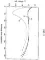
- FIG. 2 shows discharge characteristics of the cell at a first cycle of the continuous charge in low temperature;
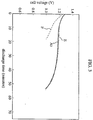
- FIG. 3 shows discharge characteristics of the cell at an eighth cycle of the continuous charge in high temperature;
- FIG. 4 is a sectional view of a nickel-metal hydride cell according to another embodiment;
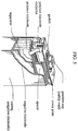
- FIG. 5 is a sectional view of a nickel-metal hydride cell according to still another embodiment; and
- FIG. 6 indicates the dendrite cell size.
- The present invention will be described in Embodiments 1-3, and Comparative examples 1-6.
- The overall configuration of a cell in the present invention will be described as referring to FIG. 1 and FIG. 4. FIG. 1 is a sectional view of a cylindrical sealed type nickelmetal hydride alkaline storage cell as an example of the present invention. The configuration of this cell is described. An electrode group 4 comprising a positive electrode 1 made of nickel active material, a negative electrode 2 including hydrogen absorbing alloy powder, and a separator 3 interposed between these positive electrode 1 and negative electrode 2 are wound together as a coil, and is housed in a
casing 6. The negative electrode 2 is electrically connected to the bottom of thecasing 6 by anegative electrode collector 5. - At the top of the
casing 6, acover plate 12 having an opening in its center is constructed via agasket 11, and apositive cap 13 is provided to thecover plate 12. A rubber plate 8 and a seal plate 9 are disposed on thiscover plate 12, and this seal plate 9 is pressed with acoil spring 10. Thepositive cap 13 and the positive electrode plate 1 are connected to each other via apositive electrode collector 7 and thecover plate 12. When the internal pressure of the cell is increased, the rubber plate 8, the seal plate 9, and thecoil spring 10 are pressed along with the A direction shown in the figure, so that a space is formed in the rubber plate 8 to release gas into air. - The cylindrical sealed type nickel-metal hydride cell thus constructed was produced according to the following method.
- Combined solution of 5 mol% of zinc sulfate and 1.5 mol% of cobalt sulfate, and sodium hydroxide solution were gradually added to nickel sulfate while adjusting its PH with aqueous ammonia. Accordingly, nickel hydroxide powder was deposited.
- Then, cobalt oxide being 10 part by weight and hydroxypropylcellulose being 0.1 part by weight were added to the above nickel hydroxide powder being 90 part by weight, then approximate amount of water was mixed with them. Thus, active material paste was generated. A foamed nickel porous matrix (thickness=about 1.6mm) was filled with this active material paste, then the foamed nickel porous matrix was dried and pressed, as a result of which a nickel electrode which was about 0.6mm in thickness was generated.
- Mischmetal (Mm: rare earth element mixture including about 20 weight% of neodymium), nickel, cobalt, aluminum, and manganese (manganese on the market whose purity is 99.9%, except Mm) were measured and mixed in the atomic ratio of 1: 3.6: 0.6: 0.2: 0.6 respectively. This alloy mixture was molten by induction heating in a high frequency induction furnace of argon gas atmosphere; the molten alloy was cooled at a cool rate of 1X10³ °C/s according to the roll method so that the dendrite cell size of its crystal was 10µm or less. As a result, a hydrogen absorbing alloy ingot represented by Mm1.0Ni3.6Co0.6Al0.2Mn0.6 was produced.
- The hydrogen absorbing alloy ingot was mechanically pulverized into hydrogen absorbing alloy powder of 100µm in average particle diameter. The dendrite cell size of the hydrogen absorbing crystal particle was about 8µm.
- This hydrogen absorbing alloy powder being 100 part by weight, polyethylene oxide being 0.5 part by weight, polyvinyl pyrrolidone being 0.5 part by weight, and polytetrafluoroethylene being 2 part by weight were kneaded with appropriate amount of water; as a result, hydrogen absorbing alloy paste was generated. The hydrogen absorbing alloy paste thus produced was pasted on a punched metal collector, accordingly a negative electrode comprising the hydrogen absorbing alloy and being 0.4mm in thickness was produced.
- It was confirmed through the X-ray diffraction method that the crystal of the hydrogen absorbing alloy had a CaCu₅ structure. This measurement of the dendrite cell size is described now. In a Mm-Ni hydrogen absorbing alloy ingot, a second branch of the coagulation structure did not grow sufficiently, as a result it coagulated like a cell. Accordingly, a line was drawn perpendicularly to the growing direction of the crystal, and the line length (L) was measured, also the number of cell borders (N) crossing the line was counted. An average length (L/N) between the cell boarders was calculated from the above data, and the calculated average length was regarded as the dendrite cell size.
- In JIS standards of nickel-cadmium storage cell, AA, 4/5A, and A sizes of sealed type nickel-metal hydride alkaline storage cells were generated as follows.
- The nickel positive electrode, the hydrogen absorbing alloy negative electrode, and separator material mainly made of non-woven olefin resin fabric were cut according to each cell size. Then, for each cell size, the positive electrode and the negative electrode were rolled via the separator material, and they were inserted into the respective size of casing.
- Next, alkaline electrolyte was generated by combining potassium hydroxide, sodium hydroxide, and lithium hydroxide in the ratio of 7: 1: 2 by mol while the total concentration of these components was about 7 mol/l.
- The alkaline electrolyte thus generated was poured into each JIS size cell so that the weight X of the electrolyte held in the separator and the weight Y of the separator material was X/(X+Y)=K (K=0.30, 0.35, 0.40, 0.45, 0.50). After pouring the electrolyte, each cell was sealed with a sealing means including the positive cap and the safety vent whose working pressures was about 15kgf/cm². Accordingly, the sealed type nickel-metal hydride alkaline cell as shown in FIG. 1 was generated, and the activation treatment which was a charge discharge operation was applied to each cell. Thus, different sizes of cells, A₁-A₅ were generated.
- The electrolyte to be poured was measured to satisfy one of the above five relations, and this will be described now. It was known from experiences that the weight X of the electrolyte held in the separator could be obtained by subtracting the weight of the electrolyte preferably held in the positive and negative electrodes from the weight of the poured electrolyte. Basing upon this knowledge, the weight of the electrolyte to be poured was calculated as follows.
- It was assumed that the weight of the electrolyte to be poured was W, the weight of the electrolyte to be preferably held in the positive and negative electrodes was Z, and the amount of the dried separator which had been measured beforehand was V. In this case, the electrolyte X to be held in the separator was


- It is apparent from the above equations that X varies depending on the sort of the separator, the weight Z of the electrolyte preferably held in the positive and negative electrodes, and the amount W of the electrolyte to be poured. Also, K must be one of the five values. Also, Z and Y are constant as long as the same sort and size of the electrode and cell are applied. Further, Y=V. Thus, by calculating beforehand the weight Z of the electrolyte to be preferably held in the positive and negative electrodes and the weight V (Y) of the separator material as well as substituting these values into Expression (3), the amount W of the electrolyte to be poured was detected. Therefore, by pouring the electrolyte W calculated from Expression (3) into each cell, the 5 cells were produced for each cell size where the ratios between the weight X of the electrolyte held in the separator and the weight Y of the separator material were the above five values. All sizes of cells (JIS: AA, 4/5A, A) are represented as follows according to the relation between the amount X of the electrolyte held in the separator and the weight Y of the separator material:





- The thickness and weight per unit of the employing separator were 0.15-0.22mm, and 60-85 g/m² respectively. The cell capacity was designed to be 1000 mAH for AA size, 1400 mAh for 4/5 A size, and 1700 mAH for A size.
- The K value for the fabricated cell was obtained after defabricating the cell by subtracting the weight V of the washed and dried separator (the weight Y of the separator material) from the weight (X+Y) of the separator containing the electrolyte.
- An AA size sealed type nickel-metal hydride alkaline cell (B) was produced substantially same as the first embodiment except that 5 mol% of cadmium sulfate was included in the positive electrode active material instead of zinc sulfate, and the weight X of the electrolyte held in the separator and the weight Y of the separator material was X/(X+Y)=0.40.
- An AA size sealed type nickel-metal hydride alkaline cell (E) was produced substantially same as the first embodiment except that the separator was made of non-woven fabric of polysulfone, and the weight X of the electrolyte held in the separator and the weight Y of the separator material was X/(X+Y)=0.40.
- An AA size sealed type nickel-metal hydride alkaline cell (J) was produced substantially same as the first embodiment except that the atomic ratio of cobalt to misch metal was 1.0 : 1, that is the composition expression of the alloy was Mm1.0Ni3.2Co1.0Al0.2Mn0.6; and the weight X of the electrolyte held in the separator and the weight Y of the separator material was X/(X+Y)=0.40.
- An AA size sealed type nickel-metal hydride alkaline cell (K) was produced substantially same as the first embodiment except that the content of neodymium in the mischmetal was set to be 50 weight% in the fabrication of the hydrogen absorbing alloy negative electrode, as well as the weight X of the electrolyte held in the separator and the weight Y of the separator material was X/(X+Y)=0.40.
- An AA size sealed type nickel-metal hydride alkaline cell (C) was produced substantially same as the first embodiment except that no zinc sulfate was added to nickel sulfate in the positive electrode, and the weight X of the electrolyte held in the separator and the weight Y of the separator material was X/(X+Y)=0.40.
- Four sorts of AA size sealed type nickel-metal hydride alkaline cells (D₁-D₄) were produced substantially same as the first embodiment except that the K values representing the relation between the weight X of the electrolyte held in the separator and the weight Y of the separator material (X/(X+Y)) were 0.20, 0.25, 0.55, 0.66.
- An AA size sealed type nickel-metal hydride alkaline cell (F) was produced substantially same as the first embodiment except that non-woven fabric of polyamide resin was included as the separator material, and the weight X of the electrolyte held in the separator and the weight Y of the separator material was X/(X+Y)=0.40; accordingly the produced cell was substantially same as the third embodiment except for the separator material.
- An AA size sealed type nickel-metal hydride alkaline cell (G) was produced substantially same as the first embodiment except that the content of neodymium in the mischmetal was set to be 10 weight% in the fabrication of the hydrogen absorbing negative alloy, as well as the weight X of the electrolyte held in the separator and the weight Y of the separator material was X/(X+Y)=0.40.
- An AA size sealed type nickel-metal hydride alkaline cell (H) was produced substantially same as the first embodiment except that the atomic ratio of cobalt to mischmetal in the hydrogen absorbing alloy was 0.4 : 1, that is the composition expression of the alloy was Mm1.0Ni3.8Co0.4Al0.2Mn0.6; and the weight X of the electrolyte held in the separator and the weight Y of the separator material was X/(X+Y)=0.40.
- An AA size sealed type nickel-metal hydride alkaline cell (I) was produced substantially same as the first embodiment except that when cooling the molten metal, it was flown into a mold at the rate of about 1x10²°C/s, accordingly the dendrite cell size of each alloy crystal was about 10 µm or more, as well as the weight X of the electrolyte held in the separator and the weight Y of the separator material was X/(X+Y)=0.40.
- More precisely, the dendrite cell size of the alloy crystal herein was about 15 µm.
- An AA size sealed type nickel-metal hydride alkaline cell (L) was produced substantially same as the first embodiment except that the atomic ratio of cobalt to mischmetal in the hydrogen absorbing alloy was 1.3 : 1, that is the composition expression of the alloy was Mm1.0Ni2.9Co1.3Al0.2Mn0.6, as well as the weight X of the electrolyte held in the separator and the weight Y of the separator material was X/(X+Y)=0.40.
- An AA size sealed type nickel-metal hydride alkaline cell (M) was produced substantially same as the first embodiment except that the content of neodymium in mischmetal was set to be 60 weight% in the fabrication of the negative electrode hydrogen absorbing alloy, and the weight X of the electrolyte held in the separator and the weight Y of the separator material was X/(X+Y)=0.40.
- In each of the cells produced according to the present invention and the cells produced according to the comparative examples, cell characteristics during the continuous charge in low temperature and high temperature were examined. The experiment was conducted under the following conditions.
- After charging each cell at 0.1C in 0°C for a month, it was returned to the room temperature, and was discharged with current of 1C until it became 1.0V. This charge/discharge cycle was applied to each cell. A cell life was defined when the cell capacity became 50% of a certain capacity, and each cell's cell capacity was determined according to its cell life.
- After charging each cell at 0.1C in 40°C for a month, it was returned to the room temperature, and was discharged with current of 1C until it became 1.0V. This charge/discharge cycle was applied to each cell. A cell life was defined when the cell capacity became 50% of a certain capacity, and each cell's cell capacity was determined according to its cell life.
- The current of 1000mAH, 1400mAH, and 1700mAH correspond to 1C for AA, 4/5A, and A cells respectively.
-
- 1) FIG. 2 shows discharge characteristics of the cells (A₃) and (B) in the present invention as well as the cell (C) in the comparative example at a first cycle of the continuous charge test in low temperature. The same size and K value were applied to these cells.
As shown in FIG. 2, the cell voltage of the cell (C) excluding zinc or cadmium dropped to 1.0V or lower immediately after the discharge started, and was recovered to 1.0V or higher along with the continuation of discharge. In contrast, the cell (A₃) which included zinc and the cell (B) which included cadmium according to the present invention did not have a rapid decrease in their cell voltage, and showed favorable discharge characteristics in low temperature. The same characteristics shown in FIG. 2 were observed at the second cycle and after, although not illustrated.
Thus, at the initial discharge stage, the rapid decrease of the cell voltage was observed in the cells which included neither zinc nor cadmium. The believed cause for this was that the nickel active material in the positive electrode became γ-NiOOH when the cell was charged in low temperature; accordingly the electrolyte was taken into the crystal layers of γ-NiOOH, so that a so-called dry-out of the separator occurred. This led a shortage of the electrolyte required for a further charge. Also, it was found that the cell voltage recovered later. The believed cause for this recovery was that γ-NiOOH was reduced into its original form as the discharge progressed, and the dry-out of the separator was improved by that. In contrast, the cells (A₃) and (B) had the effective discharge characteristics without a rapid decrease. The believed cause for this was that the cells (A₃) and (B) included either zinc or cadmium according to the present invention, and they prevented the high ordering of the active material in the positive electrode effectively, as a result the dry-out of the separator was prevented.
It was proved from the above findings that by adding zinc or cadmium to the positive electrode, the dry-out of the separator was suppressed, accordingly the deterioration of the discharge characteristics of the cell was prevented favorably. - 2) FIG. 3 shows discharge characteristics of the AA size cells (A₃) and (E) in the present invention and the cell (F) in the comparative example at a eighth cycle of the continuous charge test in high temperature. Similarly to FIG. 2, the same cell size and K value were applied to every cell.
As shown in FIG. 3, the cells (A₃) and (E) where the separators were made of polyolefin resin and polysulfone resin respectively showed favorable discharge characteristics after continuous charge in high temperature. In contrast, the cell (F) in the comparative example where the separator was made of polyamide resin fabric had a rapid decrease in the cell voltage immediately after the discharge test started.
The believed cause for the above results was that in the cell (F) the polyamide resin fabric was damaged by the electrolyte when the cell was charged in high temperature, and resolving organic substances were generated. The resolving organic substances were reacted with the oxygen generated from the positive electrode, and hence a part of the oxygen to be moved to the negative electrode was consumed. As a result, the charge reserve was shrunk, whereby hydrogen gas was generated from the negative electrode; otherwise, the electrolyte was carbonated, so that its alkali concentration was lowered. Irreversibly, the characteristics of the cell were deteriorated. In contrast, in the cells (A₃) and (E) polyolefin resin fabric and polysulfone resin fabric were employed as the separator material respectively, and these fabrics were superior in the resistance to oxidation and resolution. Therefore, the above damage to the separator did not occur in these cells and the discharge characteristics remained favorable after continuous charge in high temperature. From these results, it was proved that the deterioration of the cell characteristics during the continuous charge in high temperature was prevented favorably by including polyolefin resin fabric or polysulfone resin fabric as the separator material. - 3) Table 1 shows cycle lives of AA, 4/5 A, A sizes of cells (A₁)-(A₅) in the present invention and (D₁)-(D₄) in the comparative examples after charging the cell continuously in low temperature and high temperature. The cells in the present invention (As) and the cells in the comparative examples (Ds) were the same as each other except their K values.
As shown in Table 1, every size of the cells (A₁)-(A₅) had a favorable cell life such as 10-12 times. To be noted, in the cells (A₁)-(A₅) zinc was included in the positive electrode, polyolefin resin fabric was included as the separator material, and the electrolyte was poured to satisfy 0.3≦X/(X+Y)≦0.5 between the weight X of the electrolyte held in the separator and the weight Y of the separator material. On the other hand, the cells (D₁), (D₂) and (D₃), (D₄) had significantly shorter cycle lives than the cells (A₁)-(A₅). In the cells (D₁) and (D₂), the K value was smaller than 0.3 while in the cells (D₃) and (D₄) the K value was greater than 0.5.
The believed cause for this result was that when charging in low temperature, the take-in of the electrolyte caused by the high-ordering of the active material (generation of γ-NiOOH) effected more largely if the K value was smaller than 0.3. Also, when charging in high temperature, the carbonation of the electrolyte due to the resolution of organic substances in the separator effected more largely if the K value was smaller than 0.3. In both cases, the cell capacity was deteriorated, and the cycle life was shortened. When the K value was greater than 0.5, on the other hand, the electrolyte excessively held in the separator reduced the gas permeability of the separator; accordingly, the transmission of the oxygen and hydrogen generated from the positive electrode and negative electrode respectively was hindered. As a result, the consumption reaction of the gas was not held smoothly; the unconsumed gas was accumulated in the cell gradually; and finally the cell safety vent was forced to operate to disperse the electrolyte to outside the cell together with the gas. Accordingly, the shortage of electrolyte occurred, and the cycle life was shortened like the cells having small K values, although differing in the cause.
From the above results, it was confirmed that the cycle life of the cell improved significantly even when the cell was charged in low temperature or high temperature as long as the relation between the weight X of the electrolyte held in the separator and the weight Y of the separator material satisfied the expression of [0.3≦X/(X+Y)≦0.5], regardless of the dimension of the electrode and separator, and the absolute amount of the electrolyte to be poured. - 4) Table 2 shows cycle lives of the cells (A₃), (J), and (K) in the present invention and the cells (G), (H), (I), (L), and (M) in the comparative examples when the cells are charged continuously in high temperature. These cells had the same cell size (JIS standard: AA) and the same K value (0.4). The dendrite cell size of the cells (A₃), (G), (H), (J), (K), (L), and (M) was about 8µm, and the dendrite cell size of the cell (I) was about 15µm.
As shown in Table 2, the cycle lives of the cells in the comparative examples were shorter than those of the cells (A₃), (J), and (K) in the present invention. In the cell (G) the content of neodymium in mischmetal was 10 weight%; in the cell (M) the content of neodymium in mischmetal was 60 weight%; in the cell (H) the atomic ratio of cobalt to mischmetal was 0.4:1; in the cell (L) the atomic ratio of cobalt to mischmetal was 1.3:1; and the cell (I) was the same as the cell (A₃) in the present invention except for the dendrite cell size (10µm or more).
The believed cause for the above results was that the resistance to oxidation was decreased when content of neodymium in mischmetal or the content of cobalt determined stoichiometrically was less than that in the present invention, or the dendrite cell size of the hydrogen absorbing alloy exceeded that in the present invention. Because of the decrease in the resistance to oxidation, the hydrogen absorbing alloy in the comparative examples was gradually degraded during the continuous charge, as well as the charge reserve was reduced, so that the safety vent was forced to operate by the hydrogen gas accumulated inside the cell, accordingly a shortage of electrolyte occurred.
When the content of neodymium in the negative electrode hydrogen absorbing alloy, and the content of cobalt determined stoichiometrically exceeded those in the present invention, the capacity of the negative electrode was decreased significantly although the hydrogen absorbing alloy's resistance to oxidation was improved. As a result, it was difficult to keep a sufficient charge reserve since the ratio of the positive electrode capacity to the negative electrode capacity in the initial stage was small, although the shrinking of the charge reserve due to the deterioration of the hydrogen absorbing alloy could be minimized. Accordingly, the safety vent was forced to operate by the hydrogen gas accumulated inside the cell, and a shortage of electrolyte occurred.
From these results, it was found to be preferable that the hydrogen absorbing alloy employed as the active material for the negative electrode included mischmetal, nickel, and cobalt, as well as the dendrite cell size of the hydrogen absorbing alloy was 10µm or smaller. Also, the favorable content of neodymium in mischmetal was 20-50 weight%, and the favorable atomic ratio of cobalt to mischmetal was 0.5-1.2:1. - The present invention is not limited to the above embodiments; for example, there are the following conceivable modifications.
- (1) Although in the above embodiments, to include zinc or cadmium in the positive electrode, the solution of zinc sulfate or cadmium sulfate was poured during the preparation of the active material, they may be included by adding zinc oxide powder or cadmium oxide powder as well as by adding either of them together with the above paste.
- (2) Although in the above embodiments, to include cobalt in the positive electrode, the cobalt oxide was employed; however, cobalt metal or cobalt hydroxide may be employed alone, or more than two sorts of these cobalt may be employed together.
- (3) The dendrite cell size of the crystal particle of the hydrogen absorbing alloy is substantially equivalent to a dendrite arm spacing. The dendrite arm spacing is not excluded in the present invention; instead, the dimension of the crystal particle may be determined by the dendrite arm spacing.
- (4) Although not described in the above embodiments, hydrophilic characteristics may be added to the separator material in the present invention according to a conventional method. For example, if the separator material is disposed in the atmosphere where fluorine gas to absorb the fluorine gas, the separator material will gain the hydrophilic characteristics.
- (5) The electrolyte must be alkaline electrolyte, but its composition and alkaline concentration are not limited specifically. However, it is preferable that the electrolyte mainly includes potassium hydroxide besides the additional component of sodium hydroxide and/or lithium hydroxide; and the total concentration of these components is between 4-8 mol/l.
- (6) The shape of the cell is not limited to cylindrical; for example, the present invention may be applied to a rectangular-shaped cell as shown in FIG. 5.
- (7) The working pressure of the cell safety vent can vary. In the above examples, the working pressure of 15kgf/cm² is employed; however, the preferable working pressure is 20kgf/cm² to secure safety.
- According to the prevent invention, which has been explained in the above embodiment, the discharge characteristics of the sealed type nickel-hydride storage cell improve even in the continuous charge in low and high temperature, whereby high efficiency of the sealed type nickelmetal hydride storage cell is sustained in a wide range of temperatures, from low to high. Thus, the drawbacks of the conventional sealed type nickel-metal hydride storage cell, the deterioration of the discharge characteristics during the continuous charge in low and high temperature, is overcome by the present invention. Accordingly, usability of the sealed type nickel-metal hydride cell improves by the present invention, since it can be applied to the electronic devices to which it was not applicable conventionally as the power source or memory back-up source.
- Although the present invention has been fully described by way of examples with reference to the accompanying drawings, it is to be noted that various changes and modifications will be apparent to those skilled in the art. Therefore, unless otherwise such changes and modifications depart from the scope of the present invention, they should be construed as being included therein.

Table 2 cell cycle life (cycles) cell cycle life (cycles) A3 12 or more J 12 or more G 7 K 12 or more H 3 L 6 I 10 M 9
Claims (6)
- A sealed type nickel-metal hydride alkaline storage cell comprising:
a positive electrode which includes nickel active material as a main component, and also includes at least one element selected from a group consisting zinc and cadmium;
a negative electrode mainly comprising hydrogen absorbing alloy;
electrolyte comprising alkaline solution; and
a separator which is mainly made of non-woven polyolefin resin fabric or non-woven polysulfone resin fabric and holds the electrolyte,
wherein the amount of the electrolyte held in the separator is represented by 0.3≦X/(X+Y)≦0.5, in which X is the amount of the electrolyte held in the separator while Y is the weight of separator material. - The sealed type nickel-metal hydride alkaline storage cell of Claim 1, wherein the hydrogen absorbing alloy constituting the negative electrode comprises mischmetal being a rare earth element mixture, as well as nickel and cobalt, and a crystal of the hydrogen absorbing alloy has a CaCu₅ structure.
- The sealed type nickel-metal hydride alkaline storage cell of Claim 2, wherein the mischmetal includes neodymium which is 20-50 weight% of the total weight of the mischmetal.
- The sealed type nickel-metal hydride alkaline storage cell of Claim 2, wherein an atomic ratio of the cobalt to the mischmetal is 0.5-1.2:1.
- The sealed type nickel-metal hydride alkaline storage cell of Claim 1, wherein a dendrite cell size of a crystal particle constituting the hydrogen absorbing alloy is 10µm or smaller.
- The sealed type nickel-metal hydride alkaline storage cell of Claim 5, wherein the hydrogen absorbing alloy is obtained by cooling its molten liquid at 1x10³°C/s or faster.
Applications Claiming Priority (2)
| Application Number | Priority Date | Filing Date | Title |
|---|---|---|---|
| JP129790/93 | 1993-05-31 | ||
| JP5129790A JPH06338344A (en) | 1993-05-31 | 1993-05-31 | Sealed nickel metal hydride alkaline storage battery |
Publications (2)
| Publication Number | Publication Date |
|---|---|
| EP0627779A1 true EP0627779A1 (en) | 1994-12-07 |
| EP0627779B1 EP0627779B1 (en) | 1998-09-23 |
Family
ID=15018299
Family Applications (1)
| Application Number | Title | Priority Date | Filing Date |
|---|---|---|---|
| EP94303896A Expired - Lifetime EP0627779B1 (en) | 1993-05-31 | 1994-05-31 | Sealed type nickel-metal hydride alkaline storage cell and method of producing the same. |
Country Status (5)
| Country | Link |
|---|---|
| EP (1) | EP0627779B1 (en) |
| JP (1) | JPH06338344A (en) |
| KR (1) | KR100196098B1 (en) |
| CN (1) | CN1076888C (en) |
| DE (1) | DE69413454T2 (en) |
Cited By (2)
| Publication number | Priority date | Publication date | Assignee | Title |
|---|---|---|---|---|
| CN1085436C (en) * | 1995-05-15 | 2002-05-22 | 松下电器产业株式会社 | Ultrasonic wave electric motor |
| WO2009109324A1 (en) * | 2008-03-07 | 2009-09-11 | Johnson Controls Hybrid And Recycling Gmbh | Degassing system for an accumulator, and accumulator comprising a degassing system |
Families Citing this family (1)
| Publication number | Priority date | Publication date | Assignee | Title |
|---|---|---|---|---|
| KR100882375B1 (en) * | 2007-06-12 | 2009-02-05 | 세방전지주식회사 | Large Capacity Square Sealed Ni-MH Secondary Battery |
Citations (8)
| Publication number | Priority date | Publication date | Assignee | Title |
|---|---|---|---|---|
| JPS5842175A (en) * | 1981-09-08 | 1983-03-11 | Seiko Instr & Electronics Ltd | non-aqueous electrolyte battery |
| EP0271043A1 (en) * | 1986-12-08 | 1988-06-15 | Matsushita Electric Industrial Co., Ltd. | Sealed storage battery and method for making its electrode |
| EP0383991A2 (en) * | 1989-02-23 | 1990-08-29 | Matsushita Electric Industrial Co., Ltd. | Alkaline storage battery using hydrogen absorbing alloy |
| JPH02291665A (en) * | 1989-02-23 | 1990-12-03 | Matsushita Electric Ind Co Ltd | Alkaline storage battery and its negative electrode manufacturing method |
| EP0420669A2 (en) * | 1989-09-29 | 1991-04-03 | Kabushiki Kaisha Toshiba | Nickel-metal hydride secondary cell |
| JPH03145053A (en) * | 1989-10-31 | 1991-06-20 | Toshiba Battery Co Ltd | Nickel-hydrogen alkaline storage battery |
| DE4109764A1 (en) * | 1990-03-23 | 1991-09-26 | Sanyo Electric Co | ALKALIC STORAGE CELL |
| US5108851A (en) * | 1991-04-17 | 1992-04-28 | Sanyo Electric Co., Ltd. | Metal-hydrogen alkaline storage cell |
-
1993
- 1993-05-31 JP JP5129790A patent/JPH06338344A/en active Pending
-
1994
- 1994-05-19 KR KR1019940010890A patent/KR100196098B1/en not_active Expired - Fee Related
- 1994-05-31 CN CN94105939A patent/CN1076888C/en not_active Expired - Lifetime
- 1994-05-31 DE DE69413454T patent/DE69413454T2/en not_active Expired - Lifetime
- 1994-05-31 EP EP94303896A patent/EP0627779B1/en not_active Expired - Lifetime
Patent Citations (9)
| Publication number | Priority date | Publication date | Assignee | Title |
|---|---|---|---|---|
| JPS5842175A (en) * | 1981-09-08 | 1983-03-11 | Seiko Instr & Electronics Ltd | non-aqueous electrolyte battery |
| EP0271043A1 (en) * | 1986-12-08 | 1988-06-15 | Matsushita Electric Industrial Co., Ltd. | Sealed storage battery and method for making its electrode |
| EP0383991A2 (en) * | 1989-02-23 | 1990-08-29 | Matsushita Electric Industrial Co., Ltd. | Alkaline storage battery using hydrogen absorbing alloy |
| JPH02291665A (en) * | 1989-02-23 | 1990-12-03 | Matsushita Electric Ind Co Ltd | Alkaline storage battery and its negative electrode manufacturing method |
| EP0420669A2 (en) * | 1989-09-29 | 1991-04-03 | Kabushiki Kaisha Toshiba | Nickel-metal hydride secondary cell |
| JPH03145053A (en) * | 1989-10-31 | 1991-06-20 | Toshiba Battery Co Ltd | Nickel-hydrogen alkaline storage battery |
| DE4109764A1 (en) * | 1990-03-23 | 1991-09-26 | Sanyo Electric Co | ALKALIC STORAGE CELL |
| US5132177A (en) * | 1990-03-23 | 1992-07-21 | Sanyo Electric Co., Ltd. | Alkaline storage cell |
| US5108851A (en) * | 1991-04-17 | 1992-04-28 | Sanyo Electric Co., Ltd. | Metal-hydrogen alkaline storage cell |
Non-Patent Citations (4)
| Title |
|---|
| MINGMING GENG: "electrode characterisation of MmNi5-based alloys for nickel-metal hydride batteries", JOURNAL OF ALLOYS AND COMPOUNDS, vol. 206, no. 1, April 1994 (1994-04-01), LAUSANNE CH, pages L3 - L5 * |
| PATENT ABSTRACTS OF JAPAN vol. 15, no. 367 (E - 1112) 17 September 1991 (1991-09-17) * |
| PATENT ABSTRACTS OF JAPAN vol. 15, no. 70 (E - 1035) 19 February 1991 (1991-02-19) * |
| PATENT ABSTRACTS OF JAPAN vol. 7, no. 123 (E - 178) 27 May 1983 (1983-05-27) * |
Cited By (4)
| Publication number | Priority date | Publication date | Assignee | Title |
|---|---|---|---|---|
| CN1085436C (en) * | 1995-05-15 | 2002-05-22 | 松下电器产业株式会社 | Ultrasonic wave electric motor |
| WO2009109324A1 (en) * | 2008-03-07 | 2009-09-11 | Johnson Controls Hybrid And Recycling Gmbh | Degassing system for an accumulator, and accumulator comprising a degassing system |
| CN102007621A (en) * | 2008-03-07 | 2011-04-06 | 约翰逊控制混合动力与可循环有限责任公司 | Degassing system for an accumulator, and accumulator comprising a degassing system |
| CN102007621B (en) * | 2008-03-07 | 2013-10-16 | 约翰逊控制混合动力与可循环有限责任公司 | Exhaust system for battery and battery including exhaust system |
Also Published As
| Publication number | Publication date |
|---|---|
| KR100196098B1 (en) | 1999-06-15 |
| EP0627779B1 (en) | 1998-09-23 |
| DE69413454D1 (en) | 1998-10-29 |
| JPH06338344A (en) | 1994-12-06 |
| KR940027213A (en) | 1994-12-10 |
| DE69413454T2 (en) | 1999-05-12 |
| CN1076888C (en) | 2001-12-26 |
| HK1008372A1 (en) | 1999-05-07 |
| CN1099525A (en) | 1995-03-01 |
Similar Documents
| Publication | Publication Date | Title |
|---|---|---|
| EP0522297B1 (en) | Hydrogen storage electrode | |
| US5695530A (en) | Method for making high charging efficiency and fast oxygen recombination rechargeable hydride batteries | |
| EP0383991B2 (en) | Alkaline storage battery using hydrogen absorbing alloy | |
| US5541017A (en) | Method for making high capacity rechargeable hydride batteries | |
| EP0587974B1 (en) | Sealed metal oxide-hydrogen storage battery | |
| EP0477461B2 (en) | Nickel/hydrogen storage battery and method of manufacturing the same | |
| EP0554617B1 (en) | Active material of hydrogen storage alloy electrode | |
| EP0627779B1 (en) | Sealed type nickel-metal hydride alkaline storage cell and method of producing the same. | |
| EP0845822B1 (en) | Hydrogen absorbing alloy electrode, method of fabricating hydrogen absorbing alloy electrode, and alkali battery | |
| EP0696822B1 (en) | Sealed type alkaline battery | |
| US6322925B1 (en) | Metal hydride alkaline storage cell | |
| EP0845823B1 (en) | Hydrogen absorbing alloy electrode, method of fabricating hydrogen absorbing alloy electrode, and alkali secondary battery | |
| US6197448B1 (en) | Hydrogen storage alloy | |
| HK1008372B (en) | Sealed type nickel-metal hydride alkaline storage cell and method of producing the same | |
| US5552246A (en) | Materials for hydrogen storage, hydride electrodes and hydride batteries | |
| JP3101622B2 (en) | Nickel-hydrogen alkaline storage battery | |
| JP3096464B2 (en) | Nickel-hydrogen alkaline storage battery | |
| JP2679441B2 (en) | Nickel-metal hydride battery | |
| JP3342506B2 (en) | Hydride secondary battery and method for producing the same | |
| JPH103940A (en) | Nickel-metal hydride storage battery and its manufacture | |
| JP3746086B2 (en) | Method for manufacturing nickel-metal hydride battery | |
| JP3297375B2 (en) | Nickel hydride rechargeable battery | |
| JPH05266887A (en) | Metal-hydrogen alkaline storage battery | |
| JP2000353520A (en) | Alkaline storage battery | |
| JPH06140073A (en) | Method for manufacturing sealed alkaline storage battery |
Legal Events
| Date | Code | Title | Description |
|---|---|---|---|
| PUAI | Public reference made under article 153(3) epc to a published international application that has entered the european phase |
Free format text: ORIGINAL CODE: 0009012 |
|
| AK | Designated contracting states |
Kind code of ref document: A1 Designated state(s): DE FR GB |
|
| 17P | Request for examination filed |
Effective date: 19950501 |
|
| 17Q | First examination report despatched |
Effective date: 19951024 |
|
| GRAG | Despatch of communication of intention to grant |
Free format text: ORIGINAL CODE: EPIDOS AGRA |
|
| GRAG | Despatch of communication of intention to grant |
Free format text: ORIGINAL CODE: EPIDOS AGRA |
|
| GRAH | Despatch of communication of intention to grant a patent |
Free format text: ORIGINAL CODE: EPIDOS IGRA |
|
| GRAH | Despatch of communication of intention to grant a patent |
Free format text: ORIGINAL CODE: EPIDOS IGRA |
|
| GRAA | (expected) grant |
Free format text: ORIGINAL CODE: 0009210 |
|
| AK | Designated contracting states |
Kind code of ref document: B1 Designated state(s): DE FR GB |
|
| REF | Corresponds to: |
Ref document number: 69413454 Country of ref document: DE Date of ref document: 19981029 |
|
| ET | Fr: translation filed | ||
| PLBE | No opposition filed within time limit |
Free format text: ORIGINAL CODE: 0009261 |
|
| STAA | Information on the status of an ep patent application or granted ep patent |
Free format text: STATUS: NO OPPOSITION FILED WITHIN TIME LIMIT |
|
| 26N | No opposition filed | ||
| REG | Reference to a national code |
Ref country code: GB Ref legal event code: IF02 |
|
| PGFP | Annual fee paid to national office [announced via postgrant information from national office to epo] |
Ref country code: GB Payment date: 20130529 Year of fee payment: 20 Ref country code: DE Payment date: 20130529 Year of fee payment: 20 |
|
| PGFP | Annual fee paid to national office [announced via postgrant information from national office to epo] |
Ref country code: FR Payment date: 20130531 Year of fee payment: 20 |
|
| REG | Reference to a national code |
Ref country code: DE Ref legal event code: R071 Ref document number: 69413454 Country of ref document: DE |
|
| REG | Reference to a national code |
Ref country code: GB Ref legal event code: PE20 Expiry date: 20140530 |
|
| PG25 | Lapsed in a contracting state [announced via postgrant information from national office to epo] |
Ref country code: GB Free format text: LAPSE BECAUSE OF EXPIRATION OF PROTECTION Effective date: 20140530 |
|
| PG25 | Lapsed in a contracting state [announced via postgrant information from national office to epo] |
Ref country code: DE Free format text: LAPSE BECAUSE OF EXPIRATION OF PROTECTION Effective date: 20140603 |