EP0627555B1 - Device for pumping by a diaphragm pump operated by a hydraulic circuit - Google Patents
Device for pumping by a diaphragm pump operated by a hydraulic circuit Download PDFInfo
- Publication number
- EP0627555B1 EP0627555B1 EP94830178A EP94830178A EP0627555B1 EP 0627555 B1 EP0627555 B1 EP 0627555B1 EP 94830178 A EP94830178 A EP 94830178A EP 94830178 A EP94830178 A EP 94830178A EP 0627555 B1 EP0627555 B1 EP 0627555B1
- Authority
- EP
- European Patent Office
- Prior art keywords
- rotary
- pump
- diaphragm pump
- diaphragm
- pumping device
- Prior art date
- Legal status (The legal status is an assumption and is not a legal conclusion. Google has not performed a legal analysis and makes no representation as to the accuracy of the status listed.)
- Expired - Lifetime
Links
- 238000005086 pumping Methods 0.000 title claims description 14
- 239000007788 liquid Substances 0.000 claims description 18
- 238000006073 displacement reaction Methods 0.000 claims description 5
- 230000009467 reduction Effects 0.000 claims description 4
- 239000002184 metal Substances 0.000 claims description 3
- 238000010521 absorption reaction Methods 0.000 description 3
- 230000008901 benefit Effects 0.000 description 3
- 238000007789 sealing Methods 0.000 description 3
- VHUUQVKOLVNVRT-UHFFFAOYSA-N Ammonium hydroxide Chemical compound [NH4+].[OH-] VHUUQVKOLVNVRT-UHFFFAOYSA-N 0.000 description 2
- 238000010276 construction Methods 0.000 description 2
- 230000008878 coupling Effects 0.000 description 2
- 238000010168 coupling process Methods 0.000 description 2
- 238000005859 coupling reaction Methods 0.000 description 2
- 238000009835 boiling Methods 0.000 description 1
- 238000001816 cooling Methods 0.000 description 1
- 239000000110 cooling liquid Substances 0.000 description 1
- 229920001971 elastomer Polymers 0.000 description 1
- 239000012530 fluid Substances 0.000 description 1
- 238000007689 inspection Methods 0.000 description 1
- 238000000034 method Methods 0.000 description 1
- 230000004048 modification Effects 0.000 description 1
- 238000012986 modification Methods 0.000 description 1
- 230000008569 process Effects 0.000 description 1
- 239000011555 saturated liquid Substances 0.000 description 1
- 239000012047 saturated solution Substances 0.000 description 1
- 239000000243 solution Substances 0.000 description 1
Images


Classifications
-
- F—MECHANICAL ENGINEERING; LIGHTING; HEATING; WEAPONS; BLASTING
- F04—POSITIVE - DISPLACEMENT MACHINES FOR LIQUIDS; PUMPS FOR LIQUIDS OR ELASTIC FLUIDS
- F04B—POSITIVE-DISPLACEMENT MACHINES FOR LIQUIDS; PUMPS
- F04B43/00—Machines, pumps, or pumping installations having flexible working members
- F04B43/02—Machines, pumps, or pumping installations having flexible working members having plate-like flexible members, e.g. diaphragms
- F04B43/06—Pumps having fluid drive
- F04B43/073—Pumps having fluid drive the actuating fluid being controlled by at least one valve
-
- F—MECHANICAL ENGINEERING; LIGHTING; HEATING; WEAPONS; BLASTING
- F25—REFRIGERATION OR COOLING; COMBINED HEATING AND REFRIGERATION SYSTEMS; HEAT PUMP SYSTEMS; MANUFACTURE OR STORAGE OF ICE; LIQUEFACTION SOLIDIFICATION OF GASES
- F25B—REFRIGERATION MACHINES, PLANTS OR SYSTEMS; COMBINED HEATING AND REFRIGERATION SYSTEMS; HEAT PUMP SYSTEMS
- F25B15/00—Sorption machines, plants or systems, operating continuously, e.g. absorption type
- F25B15/02—Sorption machines, plants or systems, operating continuously, e.g. absorption type without inert gas
- F25B15/025—Liquid transfer means
Definitions
- the present invention relates to devices for the displacement of liquids and particularly a device for pumping liquids provided with a diaphragm pump which is reciprocated by a hydraulic circuit operatively connected to a rotary positive-displacement pump.
- thermodynamic apparatus such as, for example, absorption heat pump, in particular water-ammonia heat pump
- the most critical component is the pump of the near-saturated solution which must have requirements of reliability, high head, capability of operating with a near-saturated liquid, and capability of operating under "dry" conditions, i.e. without liquid to be pumped.
- the pumping devices for satisfying the requirements listed above are known; in any case, however, there are a lot of drawbacks due to several problems such as the extreme mechanical complexity with the result of high cost, the insufficient reliability, the poor capacity to the "dry” operation, and the high overall dimensions.
- the invention seeks to provide a device of the type mentioned above having all of above requirements and being of reliable operation ad easy construction.
- a pump operating under water-ammonia cooling cycles and generally comprising a diaphragm hydraulically operated with pressurized oil, two check valves for suction and delivery, respectively, and a cylindrical tank for stocking cooling liquid for starting.
- a very similar pump has been used by ARKLA Company producing refrigerating absorption machines.
- a hydraulically operated diaphragm pump is connected to a hydraulic circuit operated by a rotary pump in order to take advantage in the same machine of the operation of a diaphragm pump and a rotary pump which are, as known, cheaper, strong and reliable in the operation of a piston-connecting-rod-crank system used in the conventional diaphragm pumps.
- a diaphragm pump In a diaphragm pump the pumping operation is executed by a strong diaphragm which divides the head of the pump in two sections, the chamber for the liquid with its suction and delivery valves and the chamber for the oil, so that the outer motor does not pump directly the liquid but an intermediate hydraulic fluid with the advantage of a sealed circuit for the liquid.
- the device coupling the rotating system having unidirectional flow with the diaphragm pump having reciprocating flow is formed of a rotary distributor operating only in order to expose to the atmosphere the pipe in which the oil is flowing in the suction stroke of the diaphragm pump.
- Such solution however, has the serious problem that the diaphragm of the pump can be lowered for the suction of the liquid to be pumped only if the suction pressure is higher than the atmospheric pressure (passive suction).
- US-A-2 843500 discloses a pumping device comprising a reciprocating diaphragm pump and a rotary pump connected to said diaphragm pump through a distributor cyclically inverting the suction and delivery strokes so as to transmit said reciprocating motion to the diaphragm.
- the rotary distributor does not exibit any high performance and does not reach high operating pressures. This is due to the lack of suitable sealing devices and an automatic slack taking up device installed between the moving components of the distributor.
- a pumping device in particular for absorption heat pumps, comprising in combination a diaphragm pump, an oil stock tank, and a rotary pump coupled to a rotary distributor, wherein said rotary distributor consists of two metal disks for the automatic shim adjustment of the wear clearance hydraulically provided by the delivery pressure of the rotary pump.
- Said rotary distributor connected to the rotary pump takes out oil from the tank and delivers it under pressure below the diaphragm, thus causing the liquid above the diaphragm to be pumped, and then sucks it back to the tank with the resulting suction stroke of the liquid above the diaphragm.
- connection between oil tank and the suction valve of the rotary pump allows a vacuum suction stroke to be provided so that the diaphragm pump may operate even if the liquid to be sucked is at a lower pressure than the atmospheric pressure, as may be the case with a liquid having a low boiling point. Thanks to the automatic shim adjustment of the wear clearance, this pumping device is able to operate at high pressure without sealing problems.
- Figs. 1 and la show schematically the operation of the device during the delivery and suction strokes of the liquid to be pumped, respectively.
- Figs. 2 and 2a show the whole assembly during the strokes mentioned above.
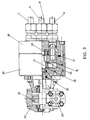
- Fig. 3 shows a detail of the reducer-distributor assembly in partial section along an axial plane.
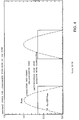
- Fig. 4 is a graphic comparing the absorbed power and the instant flow rate of a conventional alternative connecting-rod-crank pump with those of a reciprocated diaphragm pump according to the present invention.
- the device includes a diaphragm pump 10 located in the pipes of delivery 11 and suction 12 of the liquid to be pumped which are connected to the upper room 13 of said pump above the elastic diaphragm 14.
- a pipe 16 is connected on one end to the oil-containing tank 17 and on the other end to the lower room 15 of pump 10.
- Rotary pump 18 is inserted in pipe 16 and connected to a rotary distributor 19 which is provided with two curved, slantwise disposed rooms 20 and 21 defining two different flow passageways A,B and C,D.
- the oil taken out from tank 17 flows through pipe 16 and the passageways in the directions A-B and C-D and is fed to lower room 15 of pump 10.
- Diaphragm 14 is pushed upwards so as to cause the liquid to be pumped to pipe 11.
- the rotary distributor 19 When the rotary distributor 19 is in the position of Fig. 1a the oil flows in the directions C-D and A-B to tank 17, the diaphragm 14 is lowered, and the liquid to be pumped is sucked to pipe 12.
- tank 17 is sealed and provided with dip stick 34, and includes rotary pump 18 whose output shaft drives distributor 19. The operation is similar to that described above; in Fig. 2 there is shown the delivery stroke with the diaphragm 14 of pump 10 pushed downwards.
- a safety valve 23 is provided on the delivery side of rotary pump 18.
- the reducer-distributor assembly may be formed by one compact piece shown in detail in Fig. 3.
- Rotary distributor 19 provided with the passageways for the flow and the downflow of the oil is rotated through gear reduction unit 22 comprising gear wheel 24 and worm screw 25.
- gear reduction unit 22 is secured directly to valve casing 26 and is connected to disk 19 through stem 27 which is in turn supported to distribution flange 28 by ball bearing 29.
- Two sealing 0-rings indicated at 30 are placed between stem 27 and valve casing 26.
- Four pipe fittings of the oil pipes connected to the four already described passageways A-B-C-D are secured to distribution flange 28.
- An 0-ring indicated at 31 seals the distribution flange 28 to valve casing 26, while the oil pressure onto the disk seals the plane of rotary disk 19 to the plane of distribution flange 28; the initial position of disk 19 contacting flange 28 is determined by rubber seal 32 having a suitable length so as to provide a preloading on the disk during the assembling.
- a shim adjustment washer 33 has the function of avoiding that seal 32 is subjected to a torque moment during the operation of the valve.
Landscapes
- Engineering & Computer Science (AREA)
- Mechanical Engineering (AREA)
- General Engineering & Computer Science (AREA)
- Reciprocating Pumps (AREA)
Description
- The present invention relates to devices for the displacement of liquids and particularly a device for pumping liquids provided with a diaphragm pump which is reciprocated by a hydraulic circuit operatively connected to a rotary positive-displacement pump.
- In some thermodynamic apparatus such as, for example, absorption heat pump, in particular water-ammonia heat pump, the most critical component is the pump of the near-saturated solution which must have requirements of reliability, high head, capability of operating with a near-saturated liquid, and capability of operating under "dry" conditions, i.e. without liquid to be pumped.
At the present state of art several pumping devices for satisfying the requirements listed above are known; in any case, however, there are a lot of drawbacks due to several problems such as the extreme mechanical complexity with the result of high cost, the insufficient reliability, the poor capacity to the "dry" operation, and the high overall dimensions. - The invention seeks to provide a device of the type mentioned above having all of above requirements and being of reliable operation ad easy construction.
- In the USA patent No. 3,357,203 (Briggs) there is disclosed a pump operating under water-ammonia cooling cycles and generally comprising a diaphragm hydraulically operated with pressurized oil, two check valves for suction and delivery, respectively, and a cylindrical tank for stocking cooling liquid for starting.
A very similar pump has been used by ARKLA Company producing refrigerating absorption machines. In such case, a hydraulically operated diaphragm pump is connected to a hydraulic circuit operated by a rotary pump in order to take advantage in the same machine of the operation of a diaphragm pump and a rotary pump which are, as known, cheaper, strong and reliable in the operation of a piston-connecting-rod-crank system used in the conventional diaphragm pumps.
In a diaphragm pump the pumping operation is executed by a strong diaphragm which divides the head of the pump in two sections, the chamber for the liquid with its suction and delivery valves and the chamber for the oil, so that the outer motor does not pump directly the liquid but an intermediate hydraulic fluid with the advantage of a sealed circuit for the liquid. In the pump employed by ARKLA the device coupling the rotating system having unidirectional flow with the diaphragm pump having reciprocating flow is formed of a rotary distributor operating only in order to expose to the atmosphere the pipe in which the oil is flowing in the suction stroke of the diaphragm pump.
Such solution, however, has the serious problem that the diaphragm of the pump can be lowered for the suction of the liquid to be pumped only if the suction pressure is higher than the atmospheric pressure (passive suction). - US-A-2 843500 (Harper) discloses a pumping device comprising a reciprocating diaphragm pump and a rotary pump connected to said diaphragm pump through a distributor cyclically inverting the suction and delivery strokes so as to transmit said reciprocating motion to the diaphragm. However the rotary distributor does not exibit any high performance and does not reach high operating pressures. This is due to the lack of suitable sealing devices and an automatic slack taking up device installed between the moving components of the distributor.
- To overcome these inconveniences, according to the present invention there is provided a pumping device, in particular for absorption heat pumps, comprising in combination a diaphragm pump, an oil stock tank, and a rotary pump coupled to a rotary distributor, wherein said rotary distributor consists of two metal disks for the automatic shim adjustment of the wear clearance hydraulically provided by the delivery pressure of the rotary pump.
Said rotary distributor connected to the rotary pump takes out oil from the tank and delivers it under pressure below the diaphragm, thus causing the liquid above the diaphragm to be pumped, and then sucks it back to the tank with the resulting suction stroke of the liquid above the diaphragm.
The connection between oil tank and the suction valve of the rotary pump allows a vacuum suction stroke to be provided so that the diaphragm pump may operate even if the liquid to be sucked is at a lower pressure than the atmospheric pressure, as may be the case with a liquid having a low boiling point.
Thanks to the automatic shim adjustment of the wear clearance, this pumping device is able to operate at high pressure without sealing problems. - This invention will now be described with reference to the accompanying drawings which show by way of an illustrative, non-limitative example a preferred embodiment of the invention.
- In the drawings:
- Figs. 1 and la show schematically the operation of the device during the delivery and suction strokes of the liquid to be pumped, respectively.
- Figs. 2 and 2a show the whole assembly during the strokes mentioned above.
- Fig. 3 shows a detail of the reducer-distributor assembly in partial section along an axial plane.
- Fig. 4 is a graphic comparing the absorbed power and the instant flow rate of a conventional alternative connecting-rod-crank pump with those of a reciprocated diaphragm pump according to the present invention.
- With reference to Figs. 1 and 1a the device includes a
diaphragm pump 10 located in the pipes ofdelivery 11 andsuction 12 of the liquid to be pumped which are connected to theupper room 13 of said pump above theelastic diaphragm 14.
Apipe 16 is connected on one end to the oil-containingtank 17 and on the other end to thelower room 15 ofpump 10.
Rotary pump 18 is inserted inpipe 16 and connected to arotary distributor 19 which is provided with two curved, slantwise disposedrooms
When the system is under the conditions of Fig. 1 the oil taken out fromtank 17 flows throughpipe 16 and the passageways in the directions A-B and C-D and is fed tolower room 15 ofpump 10.Diaphragm 14 is pushed upwards so as to cause the liquid to be pumped to pipe 11.
When therotary distributor 19 is in the position of Fig. 1a the oil flows in the directions C-D and A-B totank 17, thediaphragm 14 is lowered, and the liquid to be pumped is sucked topipe 12.
In Figs. 2 and 2a, in which already described parts are designated by the same numerals,tank 17 is sealed and provided withdip stick 34, and includesrotary pump 18 whose outputshaft drives distributor 19. The operation is similar to that described above; in Fig. 2 there is shown the delivery stroke with thediaphragm 14 ofpump 10 pushed downwards. Asafety valve 23 is provided on the delivery side ofrotary pump 18.
Preferably, the reducer-distributor assembly may be formed by one compact piece shown in detail in Fig. 3. Rotarydistributor 19 provided with the passageways for the flow and the downflow of the oil is rotated throughgear reduction unit 22 comprisinggear wheel 24 andworm screw 25. Suchgear reduction unit 22 is secured directly tovalve casing 26 and is connected todisk 19 throughstem 27 which is in turn supported todistribution flange 28 by ball bearing 29. Two sealing 0-rings indicated at 30 are placed betweenstem 27 andvalve casing 26.
Four pipe fittings of the oil pipes connected to the four already described passageways A-B-C-D are secured todistribution flange 28.
An 0-ring indicated at 31 seals thedistribution flange 28 tovalve casing 26, while the oil pressure onto the disk seals the plane ofrotary disk 19 to the plane ofdistribution flange 28; the initial position ofdisk 19 contactingflange 28 is determined byrubber seal 32 having a suitable length so as to provide a preloading on the disk during the assembling. A shim adjustment washer 33 has the function of avoiding thatseal 32 is subjected to a torque moment during the operation of the valve.
The above-described device, as already mentioned at the beginning, can be used in all such cases where a positive-displacement high-head pump is used with the following advantages of the coupling of a diaphragm pump with a rotary pump: feasibility of easy inspection without influencing the process; greater economy; high reliability; small overall dimensions, especially in the vertical direction; lower vibrations transmitted to the pipes and the down-stream equipment; use of lower-power motors under the same efficiency.
As shown in Fig. 4, the plots of the instant flow rate and the absorbed power has the form of a square wave in contrast with the plots of a conventional alternative connecting-rod-crank pump. Therefore, both the absorbed power and the consumed power are constant and equal to the mean value of the corresponding sinusoid. As can be seen, the mean value is equal to 64% of the maximum peak.
The present invention has been illustrated and described according to a preferred embodiment thereof, however construction modifications can be made by one skilled in the art without departing from the scope of the present invention.
Claims (7)
- A pumping device, of the type comprising a reciprocating diaphragm pump casing (10) and a rotary pump (18) connected to said diaphragm pump casing trough a distributor (19) cyclically inverting the suction and delivery strokes so as to transmit said reciprocating motion to the diaphragm (14), characterized in that said rotary distributor (19) consists of two metal disks (19,28) for the automatic shim adjustment of the wear clearance hydraulically provided by the delivery pressure of the rotary pump.
- Pumping device, of the type comprising a reciprocating diaphragm pump casing (10), a rotary pump (18) and a rotary distributor (19) that transmits said reciprocating motion, said diaphragm pump (10) being operated by a hydraulic circuit formed of an oil stock tank (17), said rotary pump (18) being located between the tank (17) and the lower room (15) of the diaphragm pump casing (10), and said rotary distributor having the function of delivering and sucking said oil in reciprocating motion to said diaphragm pump casing (10) so as to cause a pulsing delivery and suction motion of the liquid to be pumped flowing to the upper room (13) of said diaphragm pump casing, said rotary distributor (19) consisting of two metal disks (19,28) for the automatic shim adjustment of the wear clearance hydraulically provided by the delivery pressure of the rotary pump.
- Pumping device according to claim 1 or 2, characterized in that the suction stroke of the liquid to be pumped is assisted by the rotary pump (18), thus allowing liquids having a lower suction pressure than the atmospheric pressure to be pumped.
- Pumping device according to the preceding claims, characterized in that said rotary distributor (19) is operated through a gear reduction unit (22) by the same drive stem (27) of the rotary positive-displacement pump (18).
- Pumping device according to the preceding claims, characterized in that the mechanical assembly comprising the positive-displacement pump (18), the gear reduction unit (22) and the rotary distributor (19) is located in a sealed tank (17) contained the oil of the hydraulic circuit operating the diaphragm pump casing.
- Pumping device according to the preceding claims, characterized in that said rotary distributor (19) comprises a pair of symmetrical rooms (20,21) located along opposite circle sectors which alternatively cause the delivery of the oil to the diaphragm pump casing and the flow of the oil from the pump back to the tank.
- Pumping device according to the preceding claims, characterized in that all of the rotary components are driven by only one motor (M) located outside said tank (17).
Applications Claiming Priority (2)
| Application Number | Priority Date | Filing Date | Title |
|---|---|---|---|
| ITRM930239A IT1262358B (en) | 1993-04-16 | 1993-04-16 | DEVICE FOR PUMPING LIQUIDS WITH MEMBRANE PUMP OPERATED BY HYDRAULIC CIRCUIT. |
| ITRM930239 | 1993-04-16 |
Publications (2)
| Publication Number | Publication Date |
|---|---|
| EP0627555A1 EP0627555A1 (en) | 1994-12-07 |
| EP0627555B1 true EP0627555B1 (en) | 1997-08-13 |
Family
ID=11401718
Family Applications (1)
| Application Number | Title | Priority Date | Filing Date |
|---|---|---|---|
| EP94830178A Expired - Lifetime EP0627555B1 (en) | 1993-04-16 | 1994-04-15 | Device for pumping by a diaphragm pump operated by a hydraulic circuit |
Country Status (4)
| Country | Link |
|---|---|
| EP (1) | EP0627555B1 (en) |
| DE (1) | DE69404899T2 (en) |
| ES (1) | ES2106487T3 (en) |
| IT (1) | IT1262358B (en) |
Families Citing this family (2)
| Publication number | Priority date | Publication date | Assignee | Title |
|---|---|---|---|---|
| IT1297087B1 (en) * | 1997-11-28 | 1999-08-03 | Enea Ente Nuove Tec | DEVICE FOR PUMPING LIQUIDS OR AERIFORMS, WITH DOUBLE ACTING ALTERNATIVE MOTION OBTAINED BY HYDRAULIC SYSTEM. |
| US6102673A (en) * | 1998-03-27 | 2000-08-15 | Hydril Company | Subsea mud pump with reduced pulsation |
Family Cites Families (4)
| Publication number | Priority date | Publication date | Assignee | Title |
|---|---|---|---|---|
| GB681139A (en) * | 1950-02-22 | 1952-10-15 | Maurice Monoyer | An improved hydraulic drive |
| US2843050A (en) * | 1954-02-15 | 1958-07-15 | Lyndus E Harper | Diaphragm sludge or chemical pump |
| GB1323006A (en) * | 1971-05-17 | 1973-07-11 | British Gas Corp | Apparatus for supplying water or other liquid other than oil at high pressure |
| US4523901A (en) * | 1981-10-17 | 1985-06-18 | Barmag Barmer Maschinenfabrick Ag | Control apparatus for a positive displacement reciprocating pump |
-
1993
- 1993-04-16 IT ITRM930239A patent/IT1262358B/en active IP Right Grant
-
1994
- 1994-04-15 ES ES94830178T patent/ES2106487T3/en not_active Expired - Lifetime
- 1994-04-15 DE DE69404899T patent/DE69404899T2/en not_active Expired - Lifetime
- 1994-04-15 EP EP94830178A patent/EP0627555B1/en not_active Expired - Lifetime
Also Published As
| Publication number | Publication date |
|---|---|
| IT1262358B (en) | 1996-06-19 |
| EP0627555A1 (en) | 1994-12-07 |
| ES2106487T3 (en) | 1997-11-01 |
| ITRM930239A1 (en) | 1994-10-16 |
| DE69404899T2 (en) | 1998-03-05 |
| ITRM930239A0 (en) | 1993-04-16 |
| DE69404899D1 (en) | 1997-09-18 |
Similar Documents
| Publication | Publication Date | Title |
|---|---|---|
| US4276003A (en) | Reciprocating piston pump system with screw drive | |
| FI61337B (en) | HYDRAULDRIVET DEPLACEMENTPUMPSYSTEM | |
| US8734139B2 (en) | Pumps and pump heads comprising volume-compensation feature | |
| KR100519390B1 (en) | High pressure pump | |
| US4522571A (en) | Peristaltic pump | |
| US5306124A (en) | Slurry pump and seal system | |
| US8182200B2 (en) | Self priming pump | |
| EP0627555A1 (en) | Device for pumping by a diaphragm pump operated by a hydraulic circuit | |
| EP0207212A1 (en) | Double acting diaphragm pump | |
| US4533301A (en) | Pump | |
| US3544239A (en) | Vacuum operated compound double-acting piston pump or compressor | |
| JPS6343591B2 (en) | ||
| CN114718911A (en) | A sewage pump seal assembly and sewage pump | |
| EP0919724A2 (en) | Hydraulically driven double acting diaphragm pump | |
| US3524715A (en) | Fluid pump | |
| US2136986A (en) | Hydraulic transmission for converting rotary into reciprocating motion | |
| US3257953A (en) | Positive displacement piston pump | |
| US5069278A (en) | Leakage control device | |
| US20060120882A1 (en) | Motor or pump assemblies | |
| US3117419A (en) | Hydraulic pump | |
| CN120906780B (en) | Double-pump system based on screw rod driven submersible electric pump and control method thereof | |
| WO2017154023A1 (en) | Motor with positive displacement helical pump inside motor shaft | |
| JPH10281056A (en) | High pressure pump | |
| CN205078413U (en) | Miniature high -pressure immersed pump | |
| US2980025A (en) | Wobble plate pump |
Legal Events
| Date | Code | Title | Description |
|---|---|---|---|
| PUAI | Public reference made under article 153(3) epc to a published international application that has entered the european phase |
Free format text: ORIGINAL CODE: 0009012 |
|
| AK | Designated contracting states |
Kind code of ref document: A1 Designated state(s): DE ES FR GB NL |
|
| 17P | Request for examination filed |
Effective date: 19950606 |
|
| 17Q | First examination report despatched |
Effective date: 19951201 |
|
| GRAG | Despatch of communication of intention to grant |
Free format text: ORIGINAL CODE: EPIDOS AGRA |
|
| GRAH | Despatch of communication of intention to grant a patent |
Free format text: ORIGINAL CODE: EPIDOS IGRA |
|
| GRAH | Despatch of communication of intention to grant a patent |
Free format text: ORIGINAL CODE: EPIDOS IGRA |
|
| GRAA | (expected) grant |
Free format text: ORIGINAL CODE: 0009210 |
|
| AK | Designated contracting states |
Kind code of ref document: B1 Designated state(s): DE ES FR GB NL |
|
| REF | Corresponds to: |
Ref document number: 69404899 Country of ref document: DE Date of ref document: 19970918 |
|
| REG | Reference to a national code |
Ref country code: ES Ref legal event code: FG2A Ref document number: 2106487 Country of ref document: ES Kind code of ref document: T3 |
|
| ET | Fr: translation filed | ||
| PLBE | No opposition filed within time limit |
Free format text: ORIGINAL CODE: 0009261 |
|
| STAA | Information on the status of an ep patent application or granted ep patent |
Free format text: STATUS: NO OPPOSITION FILED WITHIN TIME LIMIT |
|
| 26N | No opposition filed | ||
| PGFP | Annual fee paid to national office [announced via postgrant information from national office to epo] |
Ref country code: ES Payment date: 19990406 Year of fee payment: 6 |
|
| PGFP | Annual fee paid to national office [announced via postgrant information from national office to epo] |
Ref country code: GB Payment date: 19990415 Year of fee payment: 6 |
|
| PGFP | Annual fee paid to national office [announced via postgrant information from national office to epo] |
Ref country code: NL Payment date: 19990429 Year of fee payment: 6 |
|
| PG25 | Lapsed in a contracting state [announced via postgrant information from national office to epo] |
Ref country code: GB Free format text: LAPSE BECAUSE OF NON-PAYMENT OF DUE FEES Effective date: 20000415 |
|
| PG25 | Lapsed in a contracting state [announced via postgrant information from national office to epo] |
Ref country code: ES Free format text: THE PATENT HAS BEEN ANNULLED BY A DECISION OF A NATIONAL AUTHORITY Effective date: 20000417 |
|
| PG25 | Lapsed in a contracting state [announced via postgrant information from national office to epo] |
Ref country code: NL Free format text: LAPSE BECAUSE OF NON-PAYMENT OF DUE FEES Effective date: 20001101 |
|
| GBPC | Gb: european patent ceased through non-payment of renewal fee |
Effective date: 20000415 |
|
| NLV4 | Nl: lapsed or anulled due to non-payment of the annual fee |
Effective date: 20001101 |
|
| REG | Reference to a national code |
Ref country code: ES Ref legal event code: FD2A Effective date: 20020304 |
|
| PGFP | Annual fee paid to national office [announced via postgrant information from national office to epo] |
Ref country code: FR Payment date: 20100427 Year of fee payment: 17 |
|
| PGFP | Annual fee paid to national office [announced via postgrant information from national office to epo] |
Ref country code: DE Payment date: 20100430 Year of fee payment: 17 |
|
| REG | Reference to a national code |
Ref country code: DE Ref legal event code: R119 Ref document number: 69404899 Country of ref document: DE |
|
| REG | Reference to a national code |
Ref country code: DE Ref legal event code: R119 Ref document number: 69404899 Country of ref document: DE |
|
| REG | Reference to a national code |
Ref country code: FR Ref legal event code: ST Effective date: 20111230 |
|
| PG25 | Lapsed in a contracting state [announced via postgrant information from national office to epo] |
Ref country code: FR Free format text: LAPSE BECAUSE OF NON-PAYMENT OF DUE FEES Effective date: 20110502 |
|
| PG25 | Lapsed in a contracting state [announced via postgrant information from national office to epo] |
Ref country code: DE Free format text: LAPSE BECAUSE OF NON-PAYMENT OF DUE FEES Effective date: 20111031 |