EP0626265B1 - Ink jet recording apparatus controlled by presumed temperature and method therefor - Google Patents
Ink jet recording apparatus controlled by presumed temperature and method therefor Download PDFInfo
- Publication number
- EP0626265B1 EP0626265B1 EP94303828A EP94303828A EP0626265B1 EP 0626265 B1 EP0626265 B1 EP 0626265B1 EP 94303828 A EP94303828 A EP 94303828A EP 94303828 A EP94303828 A EP 94303828A EP 0626265 B1 EP0626265 B1 EP 0626265B1
- Authority
- EP
- European Patent Office
- Prior art keywords
- temperature
- head
- ink
- ejection
- recording head
- Prior art date
- Legal status (The legal status is an assumption and is not a legal conclusion. Google has not performed a legal analysis and makes no representation as to the accuracy of the status listed.)
- Expired - Lifetime
Links
Images


Classifications
-
- B—PERFORMING OPERATIONS; TRANSPORTING
- B41—PRINTING; LINING MACHINES; TYPEWRITERS; STAMPS
- B41J—TYPEWRITERS; SELECTIVE PRINTING MECHANISMS, i.e. MECHANISMS PRINTING OTHERWISE THAN FROM A FORME; CORRECTION OF TYPOGRAPHICAL ERRORS
- B41J2/00—Typewriters or selective printing mechanisms characterised by the printing or marking process for which they are designed
- B41J2/005—Typewriters or selective printing mechanisms characterised by the printing or marking process for which they are designed characterised by bringing liquid or particles selectively into contact with a printing material
- B41J2/01—Ink jet
- B41J2/015—Ink jet characterised by the jet generation process
- B41J2/04—Ink jet characterised by the jet generation process generating single droplets or particles on demand
- B41J2/045—Ink jet characterised by the jet generation process generating single droplets or particles on demand by pressure, e.g. electromechanical transducers
- B41J2/04501—Control methods or devices therefor, e.g. driver circuits, control circuits
- B41J2/0454—Control methods or devices therefor, e.g. driver circuits, control circuits involving calculation of temperature
-
- B—PERFORMING OPERATIONS; TRANSPORTING
- B41—PRINTING; LINING MACHINES; TYPEWRITERS; STAMPS
- B41J—TYPEWRITERS; SELECTIVE PRINTING MECHANISMS, i.e. MECHANISMS PRINTING OTHERWISE THAN FROM A FORME; CORRECTION OF TYPOGRAPHICAL ERRORS
- B41J2/00—Typewriters or selective printing mechanisms characterised by the printing or marking process for which they are designed
- B41J2/005—Typewriters or selective printing mechanisms characterised by the printing or marking process for which they are designed characterised by bringing liquid or particles selectively into contact with a printing material
- B41J2/01—Ink jet
- B41J2/015—Ink jet characterised by the jet generation process
- B41J2/04—Ink jet characterised by the jet generation process generating single droplets or particles on demand
- B41J2/045—Ink jet characterised by the jet generation process generating single droplets or particles on demand by pressure, e.g. electromechanical transducers
- B41J2/04501—Control methods or devices therefor, e.g. driver circuits, control circuits
- B41J2/04563—Control methods or devices therefor, e.g. driver circuits, control circuits detecting head temperature; Ink temperature
-
- B—PERFORMING OPERATIONS; TRANSPORTING
- B41—PRINTING; LINING MACHINES; TYPEWRITERS; STAMPS
- B41J—TYPEWRITERS; SELECTIVE PRINTING MECHANISMS, i.e. MECHANISMS PRINTING OTHERWISE THAN FROM A FORME; CORRECTION OF TYPOGRAPHICAL ERRORS
- B41J2/00—Typewriters or selective printing mechanisms characterised by the printing or marking process for which they are designed
- B41J2/005—Typewriters or selective printing mechanisms characterised by the printing or marking process for which they are designed characterised by bringing liquid or particles selectively into contact with a printing material
- B41J2/01—Ink jet
- B41J2/015—Ink jet characterised by the jet generation process
- B41J2/04—Ink jet characterised by the jet generation process generating single droplets or particles on demand
- B41J2/045—Ink jet characterised by the jet generation process generating single droplets or particles on demand by pressure, e.g. electromechanical transducers
- B41J2/04501—Control methods or devices therefor, e.g. driver circuits, control circuits
- B41J2/04565—Control methods or devices therefor, e.g. driver circuits, control circuits detecting heater resistance
-
- B—PERFORMING OPERATIONS; TRANSPORTING
- B41—PRINTING; LINING MACHINES; TYPEWRITERS; STAMPS
- B41J—TYPEWRITERS; SELECTIVE PRINTING MECHANISMS, i.e. MECHANISMS PRINTING OTHERWISE THAN FROM A FORME; CORRECTION OF TYPOGRAPHICAL ERRORS
- B41J2/00—Typewriters or selective printing mechanisms characterised by the printing or marking process for which they are designed
- B41J2/005—Typewriters or selective printing mechanisms characterised by the printing or marking process for which they are designed characterised by bringing liquid or particles selectively into contact with a printing material
- B41J2/01—Ink jet
- B41J2/015—Ink jet characterised by the jet generation process
- B41J2/04—Ink jet characterised by the jet generation process generating single droplets or particles on demand
- B41J2/045—Ink jet characterised by the jet generation process generating single droplets or particles on demand by pressure, e.g. electromechanical transducers
- B41J2/04501—Control methods or devices therefor, e.g. driver circuits, control circuits
- B41J2/04573—Timing; Delays
-
- B—PERFORMING OPERATIONS; TRANSPORTING
- B41—PRINTING; LINING MACHINES; TYPEWRITERS; STAMPS
- B41J—TYPEWRITERS; SELECTIVE PRINTING MECHANISMS, i.e. MECHANISMS PRINTING OTHERWISE THAN FROM A FORME; CORRECTION OF TYPOGRAPHICAL ERRORS
- B41J2/00—Typewriters or selective printing mechanisms characterised by the printing or marking process for which they are designed
- B41J2/005—Typewriters or selective printing mechanisms characterised by the printing or marking process for which they are designed characterised by bringing liquid or particles selectively into contact with a printing material
- B41J2/01—Ink jet
- B41J2/015—Ink jet characterised by the jet generation process
- B41J2/04—Ink jet characterised by the jet generation process generating single droplets or particles on demand
- B41J2/045—Ink jet characterised by the jet generation process generating single droplets or particles on demand by pressure, e.g. electromechanical transducers
- B41J2/04501—Control methods or devices therefor, e.g. driver circuits, control circuits
- B41J2/0458—Control methods or devices therefor, e.g. driver circuits, control circuits controlling heads based on heating elements forming bubbles
-
- B—PERFORMING OPERATIONS; TRANSPORTING
- B41—PRINTING; LINING MACHINES; TYPEWRITERS; STAMPS
- B41J—TYPEWRITERS; SELECTIVE PRINTING MECHANISMS, i.e. MECHANISMS PRINTING OTHERWISE THAN FROM A FORME; CORRECTION OF TYPOGRAPHICAL ERRORS
- B41J2/00—Typewriters or selective printing mechanisms characterised by the printing or marking process for which they are designed
- B41J2/005—Typewriters or selective printing mechanisms characterised by the printing or marking process for which they are designed characterised by bringing liquid or particles selectively into contact with a printing material
- B41J2/01—Ink jet
- B41J2/015—Ink jet characterised by the jet generation process
- B41J2/04—Ink jet characterised by the jet generation process generating single droplets or particles on demand
- B41J2/045—Ink jet characterised by the jet generation process generating single droplets or particles on demand by pressure, e.g. electromechanical transducers
- B41J2/04501—Control methods or devices therefor, e.g. driver circuits, control circuits
- B41J2/04588—Control methods or devices therefor, e.g. driver circuits, control circuits using a specific waveform
-
- B—PERFORMING OPERATIONS; TRANSPORTING
- B41—PRINTING; LINING MACHINES; TYPEWRITERS; STAMPS
- B41J—TYPEWRITERS; SELECTIVE PRINTING MECHANISMS, i.e. MECHANISMS PRINTING OTHERWISE THAN FROM A FORME; CORRECTION OF TYPOGRAPHICAL ERRORS
- B41J2/00—Typewriters or selective printing mechanisms characterised by the printing or marking process for which they are designed
- B41J2/005—Typewriters or selective printing mechanisms characterised by the printing or marking process for which they are designed characterised by bringing liquid or particles selectively into contact with a printing material
- B41J2/01—Ink jet
- B41J2/015—Ink jet characterised by the jet generation process
- B41J2/04—Ink jet characterised by the jet generation process generating single droplets or particles on demand
- B41J2/045—Ink jet characterised by the jet generation process generating single droplets or particles on demand by pressure, e.g. electromechanical transducers
- B41J2/04501—Control methods or devices therefor, e.g. driver circuits, control circuits
- B41J2/04591—Width of the driving signal being adjusted
-
- B—PERFORMING OPERATIONS; TRANSPORTING
- B41—PRINTING; LINING MACHINES; TYPEWRITERS; STAMPS
- B41J—TYPEWRITERS; SELECTIVE PRINTING MECHANISMS, i.e. MECHANISMS PRINTING OTHERWISE THAN FROM A FORME; CORRECTION OF TYPOGRAPHICAL ERRORS
- B41J2/00—Typewriters or selective printing mechanisms characterised by the printing or marking process for which they are designed
- B41J2/005—Typewriters or selective printing mechanisms characterised by the printing or marking process for which they are designed characterised by bringing liquid or particles selectively into contact with a printing material
- B41J2/01—Ink jet
- B41J2/015—Ink jet characterised by the jet generation process
- B41J2/04—Ink jet characterised by the jet generation process generating single droplets or particles on demand
- B41J2/045—Ink jet characterised by the jet generation process generating single droplets or particles on demand by pressure, e.g. electromechanical transducers
- B41J2/04501—Control methods or devices therefor, e.g. driver circuits, control circuits
- B41J2/04598—Pre-pulse
-
- B—PERFORMING OPERATIONS; TRANSPORTING
- B41—PRINTING; LINING MACHINES; TYPEWRITERS; STAMPS
- B41J—TYPEWRITERS; SELECTIVE PRINTING MECHANISMS, i.e. MECHANISMS PRINTING OTHERWISE THAN FROM A FORME; CORRECTION OF TYPOGRAPHICAL ERRORS
- B41J2/00—Typewriters or selective printing mechanisms characterised by the printing or marking process for which they are designed
- B41J2/005—Typewriters or selective printing mechanisms characterised by the printing or marking process for which they are designed characterised by bringing liquid or particles selectively into contact with a printing material
- B41J2/01—Ink jet
- B41J2/17—Ink jet characterised by ink handling
- B41J2/195—Ink jet characterised by ink handling for monitoring ink quality
-
- B—PERFORMING OPERATIONS; TRANSPORTING
- B41—PRINTING; LINING MACHINES; TYPEWRITERS; STAMPS
- B41J—TYPEWRITERS; SELECTIVE PRINTING MECHANISMS, i.e. MECHANISMS PRINTING OTHERWISE THAN FROM A FORME; CORRECTION OF TYPOGRAPHICAL ERRORS
- B41J2/00—Typewriters or selective printing mechanisms characterised by the printing or marking process for which they are designed
- B41J2/005—Typewriters or selective printing mechanisms characterised by the printing or marking process for which they are designed characterised by bringing liquid or particles selectively into contact with a printing material
- B41J2/01—Ink jet
- B41J2/135—Nozzles
- B41J2/14—Structure thereof only for on-demand ink jet heads
- B41J2002/14379—Edge shooter
Definitions
- This invention relates to an ink jet recording apparatus and method which perform various controls using a presumed head temperature, more particularly, to ink jet recording apparatus and method in which stabilization of ink ejection and detection of ejection failure are effected by use of a presumed head temperature.
- Recording apparatus such as printers, copying machines and facsimile terminal equipment are constructed to record images consisting of dot-patterns onto recording materials such as plastic sheet.
- Recording apparatus can be classified into various types such as ink-jet, wire-dot, thermal, laser-beam etc., according to the recording method used.
- An ink-jet printer (ink-jet recording apparatus) is constructed to supply ink drops from an orifice or outlet of the recording head onto the recording material.
- the ink-jet recording apparatus can satisfy these requirements.
- this ink-jet recording apparatus ejects ink from the recording head, the stabilization of both ink ejection and the amount of ejected ink that is required to fulfill the above requirements is greatly influenced by the ink temperature at the ink ejection orifice.
- the ink temperature is too low, the viscosity of the ink will increase abnormally and the ink, will not be ejected by the normal ejection energy; if the temperature is too high, the ejected ink quantity will increase and the ink will overflow on the recording paper, leading to deterioration of the print quality.
- a method of controlling the ink temperature at the ejection opening to be within a desired range using a temperature sensor mounted on the recording head or a method of controlling ink ejection recovery have been used.
- a heating element mounted on the recording head is used for said temperature control where the ink-jet recording apparatus is arranged to eject ink by using heat energy, i.e. in apparatus that ejects ink drops by bubble generation by ink film boiling, the ejection heater Itself may be sometimes used for this purpose.
- the ejection heater must be supplied with electric current such that no bubble generation occurs.
- the temperature measurement circuit can easily be influenced by electrostastic noise and, when operating the ejection heater or temperature regulating heater, noise occurs under the influence of driving pulses or temperature regulating current. Therefore without considerable antistatic measures, it is not possible to measure temperature exactly.
- temperature detection by the temperature sensor in order to avoid detection errors, a method is used in which the average of several previously detected head temperatures is used as the present temperature. But by averaging the several detected temperatures, the dynamic temperature change at the recording head will be averaged, and a time delay will occur between the real temperature and the detected value (bad response), so that exact feedback control is not possible.
- temperature fluctuation is calculated by accumulation of the hysterisis of the energy supplied to the recording head. Therefore an error can occur between the real head temperature and the calculated head temperature.
- recording apparatus equipped with an exchangeable recording head there is also the problem of recording head differences. Different recording heads mounted on the recording apparatus may have varying ejection quantities and heat radiation characteristics due to manufacturing errors, and different heat transfer rates because of difference in elements (adhesive layer etc.). It is difficult to take these differences into consideration in the calculation of the head temperature. As a result, errors occur between the real head temperature and the calculated head temperature.
- Japanese Patent Publication No. 5-31906 a high measuring precision is achieved by correcting the values (tables etc.) used for the calculation using the difference between the temperature detected by temperature detecting means on the recording head in a thermally stable state and a presumed calculated temperature.
- the correction of the temperature detecting means is conducted by means of ambient temperature detecting means contained in the recording apparatus which operate at times at which recording is not done, or at times at which the temperature does not change.
- the ratio of the temperature detected by the temperature detecting means to the calculated temperature is used to correct calculated temperature.
- the temperature calculation method is to presume temperature behavior (rising temperature) by, for an object whose temperature has risen as a result of energy supplied within a time unit, presetting the degree by which the temperature of the object subsequently drops in each time unit, and by calculating the sum of said degrees to the present.
- an ink-jet recording head is left unused for a long time, increased ink viscosity, particularly in the ink channel near the ejection outlet, ink is not ejected normally and, when ink ejection occurs continuously in such cases as recording with relatively high printing duty is performed, small bubbles can grow in the ink in the ink channels during ejection, and bubbles remaining in the channels can influence the ejection, so that normal ejection is not possible. Besides the above mentioned bubbles that grow in accordance with the ejection, bubbles can enter the ink at joints in the ink supply lines.
- the above mentioned ejection failure can not only reduce the reliability of recording apparatus but can also damage the recording head itself and lead to a reduction of durability, because, when printing with high duty is performed by a recording head that cannot eject ink normally, the temperature at the recording head will rise to a significantly higher temperature than in the case where the recording head is in the normal state.
- the surface of the ejection opening on the recording head may be covered with a cap when ink is not being ejected to prevent increase of ink viscosity.
- ink may be sucked from the ejection outlet while the head is capped so as to eject increased viscosity ink.
- ejection recovery such as idle ejection in which ink is ejected into a certain ink sucking body consisting of an ink absorber etc may be used to discharge high viscosity ink.
- Such ejection recovery to prevent ejection failure is conducted automatically when the power is switched on, or at certain intervals during recording or by the user depressing a recovery button whenever necessary.
- ink failure detection is executed, and if the state of the recording head is determined to be an "ink failure state", ejection recovery is performed. By these measures unnecessary ejection recovery can be avoided, and ink consumption and waste ink can be reduced.
- an ink-jet recording apparatus in which the recording head is supplied with ink from an ink cartridge which the user replaces when it is empty, does not have the function of detecting when the ink cartridge is empty, the recording head will not be supplied with ink, and will enter the ink ejection failure state. Every time this situation occurs, the recording head will be in danger because of excessive temperature rise.
- EP-A-0505154 describes a thermal ink jet recording head temperature control wherein the head temperature is presumed front the surrounding temperature (using a sensor on a main PCB) and a table which determines an error from the surrounding temperature, and the supplied power (print duty ratio).
- EP-A-0505154 describes an ink jet recording apparatus wherein an operational temperature is predicted on the basis of a non-recording temperature and a print duty ratio.
- an ink jet recording apparatus in accordance with claim 1.
- the present invention also provides an ink jet recording method in accordance with claim 10.
- An embodiment of the present invention provides an ink-jet recording apparatus in which the temperature on the recording head can be presumed with high precision, and a recording method therefor.
- An embodiment of the invention provides an ink-jet recording apparatus in which stabilization of ink ejection and detection of ink ejection failure can be performed very accurately, and a recording method therefor.
- An embodiment of the invention provides a recording apparatus in which information such as the characteristics of various recording heads can be measured exactly, and very accurate control can be achieved, and the startup time after the switching on power will be shortened, and a recording method therefor.
- An embodiment of this invention avoids wasting ink and maintains reliability by optimizing a recovery operation at the time when power is switched on.
- An embodiment avoids ink ejection failure (sometimes referred to herein as "unejection") by detecting the normal ejection very accurately.
- FIG. 1 An arrangement of a recording head in a preferable ink jet recording apparatus (IJRA) will be described below together with an operation of the recording head.
- a recording head (IJH) 5012 is coupled to an ink tank (IT) 5001.
- IJC exchangeable integrated cartridge
- a carriage (HC) 5014 is used for mounting the cartridge (IJC) to a printer main body.
- a guide 5003 scans the carriage in the sub-scan direction.
- a platen roller 5000 scans a print medium P in the main scan direction.
- a temperature sensor 5024 measures the surrounding temperature in the apparatus.
- the carriage 5014 is connected to a printed circuit board (not shown) comprising an electrical circuit (the temperature sensor 5024, and the like) for controlling the printer through a flexible cable (not shown) for supplying a signal pulse current and a head temperature control current which drive the recording head 5012 and a detected signal current given from a temperature detecting member.
- the carriage HC has a pin (not shown) to be engaged with a spiral groove 5004 of a lead screw 5005, which is rotated through driving power transmission gears 5011 and 5009 in cooperation with the normal/reverse rotation of a driving motor 5013.
- the carriage HC can be reciprocally moved in directions of arrows a and b.
- a paper pressing plate 5002 presses a paper sheet against the platen roller 5000 across the carriage moving direction.
- Photocouplers 5007 and 5008 serve as home position detection means for detecting the presence of a lever 5006 of the carriage HC in a corresponding region and switching the rotating direction of the motor 5013.
- a member 5016 supports a cap member 5022 for capping the front surface of the recording head.
- a suction means 5015 draws the interior of the cap member by vacuum suction, and performs a suction recovery process of the recording head 5012 through an opening 5023 in the cap member.
- a cleaning blade 5017 is supported by a member 5019 to be movable in the back-and-forth direction.
- the cleaning blade 5017 and the member 5019 are supported on a main body support plate 5018.
- the blade is not limited to this shape, and a known cleaning blade can be applied , as a matter of course.
- a lever 5012 is used for starting the suction operation in the suction recovery process, and is moved upon movement of a cam 5020 to be engaged with the carriage HC.
- the movement control of the lever 5021 is made by a known transmission means such as a clutch switching means for transmitting the driving force from the driving motor.
- the capping, cleaning, and suction recovery processes can be performed at corresponding positions upon operation of the lead screw 5005 when the carriage HC reaches a home position region.
- This apparatus is not limited to this as long as desired operations are performed at known timings.
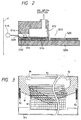
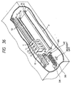
- Fig. 2 shows the details of the recording head 5012.
- a heater board 5100 formed by a semiconductor manufacturing process is arranged on the upper surface of a support member 5300.
- a temperature control heater (temperature rise heater) 5110 formed by the same semiconductor manufacturing process, for keeping and controlling the temperature of the recording head 5012, is arranged on the heater board 5100.
- a wiring board 5200 is arranged on the support member 5300, and is connected to the temperature control heater 5110 and ejection (main) heaters 5113 through, e.g., bonding wires (not shown).
- the temperature control heater 5110 may be realized by adhering a heater member formed in a process different from that of the heater board 5100 to, e.g., the support member 5300.
- a bubble 5114 is produced by heating an ink by the corresponding ejection heater 5113.
- An ink droplet 5115 is ejected from the corresponding nozzle portion 5029.
- the ink to be ejected flows from a common ink chamber 5112 into the recording head.
- Fig. 3 shows a preferred heater board of the recording head. Temperature sensors, temperature control heaters and ejection heaters are arranged on the heater board.
- Fig. 3 is a schematic top plan view of the heater board. Temperature control (sub) heaters 8d, an ejection portion line 8g on which ejection (main) heaters 8c is arranged, driving elements 8h and temperature sensors 8e are formed on the same board with the arrangement as shown in Fig. 3.
- a pair of temperature sensors 8e are arranged on the Si board 853, respectively on the right and left sides of the line where a plurality of the ejection heaters 8c are arranged.
- a mean value of temperatures detected by the two temperature sensors 8e is adopted as a detected temperature.
- the head temperature presuming means presumes the temperature of the recording head by connecting the temperature sensors, which sense the surrounding temperature in the apparatus, to the main body, detecting a change of the recording head in response to the surrounding temperature using calculation processing described below.
- the head temperature is presumed basically by using the following heat conduction formulas:
- the chip temperature of the recording head can be theoretically presumed by calculating the formulas (1) and (2) according to the print duty in correspondence with a plurality of thermal time constants.
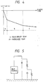
- the present inventors sampled data in the temperature rise process of the recording head by applying energy to the recording head with the above arrangement, and obtained the result shown in Fig. 4.
- the recording head with the above arrangement is constituted by combining many members having different heat conduction times.
- Fig. 4 reveals that such many heat conduction times can be processed as a heat conduction time of a single member in practice in ranges where the differential value of the function of the log-converted increased temperature data and the elapse time is constant (i.e., ranges A, B, and C having constant inclinations).
- the recording head processed using two thermal time constants.
- the above-mentioned result indicates that feedback control can be more precisely performed upon modeling having three thermal time constants.
- the inclinations in areas B and C in Fig. 4 are almost equal to each other, and the recording head is modeled using two thermal time constants in consideration of calculation efficiency. More specifically, one heat conduction is a model having a time constant at which the temperature is increased to the equilibrium temperature in 0.8 sec. (corresponding to the area A in Fig. 4), and the other heat conduction is given by a model having a time constant at which the temperature is increased to the equilibrium temperature in 512 sec. (i.e., a model of the areas B and C in Fig. 4).
- the recording head is processed as follows to obtain a model.
- Fig. 5 shows a modelled heat conduction equivalent circuit.
- Fig. 5 illustrates only one heat source. However, when two heat sources are used, they may be connected in series with each other.
- Formula ⁇ 2-n ⁇ equal to the temperature of the object at time nt when heating is performed from time 0 to time nt, and the heat source is kept OFF from time t to time nt.
- Formula ⁇ 2-3 ⁇ equal to the temperature of the object at time nt when heating is performed from time (n-3)t to time (n-2)t, and the heat source is kept OFF from time (n-2)t to time nt.
- Formula ⁇ 2-2 ⁇ equal to the temperature of the object at time nt when heating is performed from time (n-2)t to time (n-1)t, and the heat source is kept OFF from time (n-1)t to time nt.
- Formula ⁇ 2-1 ⁇ equal to the temperature of the object at time nt when heating is performed from time (n-1)t to time nt.
- a change in temperature (increase in temperature) of the object 1 is calculated by obtaining a decreased temperature after an elapse of unit time from a temperature increased by energy supplied in unit time (corresponding to each of the formulas ⁇ 2-1 ⁇ , ⁇ 2-2 ⁇ , whil, ⁇ 2-n ⁇ ), and a total sum of decreased temperatures at the present time from temperatures increased in respective past unit times is calculated to presume the current temperature of the object 1 ( ⁇ 2-1 ⁇ + ⁇ 2-2 ⁇ + Vietnamese+ ⁇ 2-n ⁇ ).
- the chip temperature of the recording head is calculated (heat source * thermal time constant 2) four times based on the above-mentioned modeling.
- the required calculation times and data hold times for the four calculations are as shown in Fig. 22.
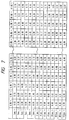
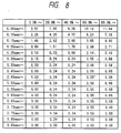
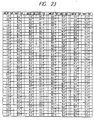
- Figs. 6 to 9 show calculation tables used for calculating the head temperature, and each comprising a two-dimensional matrix of input energy and elapse time.
- Fig. 6 shows a calculation table when ejection heaters are used as the heat source, and a member group having a short-range time constant is used;
- Fig. 7 shows a calculation table when ejection heaters are used as the heat source, and a member group having a long-range time constant is used;
- Fig. 8 shows a calculation table when sub-heaters are used as the heat source, and a member group having a short-range time constant is used; and Fig. 9 shows a calculation table when sub-heaters are used as the heat source, and a member group having a long-range time constant is used.
- the recording head constituted by combining a plurality of members having different heat conduction times is modeled to be substituted with a smaller number of thermal time constants than that in practice, the following effects can be obtained.
- the temperature calculation algorithm processes temperature shift of the recording head as an accumulation of discrete values in an unit time, calculates the temperature shift in advance based on the corresponding discrete values within a range of energy which can be input, and tables the calculation result using the table constituted by a two-dimensional matrix of input energy and elapse time.
- the recording head constituted by combining a plurality of members having different heat conduction times is modeled to be substituted with a smaller number of thermal time constants than that in practice, and calculations are performed while grouping required calculation intervals and required data hold times in units of model units (thermal time constants).
- a plurality of heat source are set, temperature rise widths are calculated in units of model units for each heat source, and the calculated widths are added later to calculate the head temperature (plural heat source calculation algorithm), thus calculating entire temperature shift of the recording head upon calculation processing in an economical recording apparatus without providing a temperature sensor in the recording head.
- this example monitors the head temperature by the head temperature sensors 8e on the HB board shown in Fig. 3.
- processing operations for reducing the noise can be performed by, e.g., collecting outputs of the temperature sensors plural times and calculating the mean value of the recording head.
- This example decides whether or not the recording head is in an unejection state according to the recording head temperature and the presumed temperature of the recording head obtained by using a presuming calculation.
- the condition of decision is as follows: (recording head temperature)-(presumed temperature) > ⁇ Tth where, ⁇ Tth is set as large as an error decision can not be produced by noise signals, but as small as the decision can be immediately obtained when unejection has produced.
- Figs. 10A to 10C are graphs each showing a monitored recording head temperature (the mean value of four times), a presumed calculation value of the recording head and a value obtained by subtracting the presumed calculation value from the recording head temperature (hereinbelow, the value subtracting the presumed calculation value from the recording head temperature is called as ⁇ T).
- ⁇ T is over ⁇ Tth as soon as unejection occurs, at this point, abnormal ejection is decided.
- the decision of whether the recording head is in an unejection state is performed in a constant time interval.
- ejection recovery processes may be performed immediately.
- the following decision can be also performed. That is, the decision of whether or not the recording head is in an unejection state is certainly performed by measuring temperature change quantities in both temperature rise and temperature reduction according to idle ejection as described in the background of the invention in the specification.
- Fig 12 is a flow chart of the decision of unejection.
- a head temperature is sensed by sensors at step S110, a presumed value of the head temperature is calculated at step S120 and ⁇ T and ⁇ Tth are compared with each other at step S130 (first decision A mode shown in Fig. 11B). Even if an unejection state is decided, for performing further certain decision, the unejection state is decided again by measuring temperature rise and temperature reduction at step S140 (final decision B mode shown in Fig. 11B).
- the unejection state is decided by using differences in temperature of both temperature rise and temperature reduction as shown above, thus certainly detecting unjection even if the recording head is slightly in a temperature reduction state. If the unejection state of the recording head is decided only when the recording head has few temperature changes, it can be decided by using only one difference in temperature of either temperature rise or temperature reduction.
- suction recovery processes are performed at step S150.
- the recording head is decided again to be in the unejection state by measuring temperature change quantities in both temperature rise and temperature reduction according to idle ejection, checking whether or not the recording head has returned in a normal state. If it is in a normal state, ejection recovery processes are completed. However, if it is in the unejection state in spite of suction recovery processes being done, error indication is performed to alarm to a user.
- ⁇ Tth used for deciding the unejection can be changed according to the state of the recording apparatus.
- the head temperature presumption means and the head temperature monitoring means are the same as in the embodiment 1.
- Fig. 13 shows the construction of the recording part of the ink-jet recording apparatus used in the second example.
- 701 indicates the ink cartridges. These consist of ink tanks filled with color inks - black, cyan, magenta and yellow - and a multi-head 702.
- Fig. 14 multi-nozzles arranged on the multi-head are shown from the z-direction.
- 801 indicates the multi-nozzles arranged on the multi-head 702.
- 703 indicates a paper transport roller which rotates in the arrow direction depressing the printing paper together with the axially roller 704, and transports the printing paper in the y-direction.
- 705 indicates a paper feed roller which feeds the printing paper and depresses the printing paper like 703 and 704.
- 706 is a carriage that supports and moves the 4 ink cartridges. This stays at the home position (h) indicated by dotted lines while the printing is not performed, or while the recovery procedure for the multi-head is being performed.
- the carriage (706) which is standing at the position indicated in the drawing (home position) moves in the x direction, and performs the printing for the width L on the paper by n multi-nozzles of the multi-head (702).
- the carriage returns to the home portion, and performs the printing in the x-direction again.
- the recording apparatus when the recording apparatus is not used as a monochrome printer for printing only characters, but is to be used to print images, various factors such as color development, tone, uniformity must be taken into consideration. Particularly as for the uniformity, slight differences of the nozzles caused in fabrication thereof can influence ink ejection quantity and ejection direction and deteriorate printing quality with uniformity in density.
- Figs. 15A to 15C and 16A to 16C These were printed by a monochrome recording head in order to simplify the explanation.
- Fig. 15A 91 indicates the multi-head; the multi-head is similar to that in the Fig. 14, but it shall be assumed that it consists of 8 multi-nozzles (92) to simplify the explanation.
- 93 indicates ink droplets ejected by the multi-nozzle 92. It is ideal that the ejection take place in uniform quantity and in the uniform direction, as shown in this drawing. When the ejection is performed in this manner, uniform size of dots will drop on the paper (Fig. 15B), and a uniform image will be obtained (Fig. 15C).
- each nozzle is slightly different and if the printing would be performed as described above ink drops ejected through each nozzle will be not uniform in size and direction, as shown in the Fig. 16A, and the ink drops fall on the paper as shown in Fig. 16B.
- main scanning direction periodically blank spots that cannot fulfill the area factor of 100%, or conversely, dots are overlapping unnecessarily, or, as it can be seen in the middle of the drawing, white stripes.
- the clusters of dots fallen onto the paper form density distribution shown in Fig. 16C in the nozzle alignment direction. This is perceived by human eyes as ununiform density.
- the recording apparatus used in the second example when printing diagrams, the divided recording method in which the printing is performed in two scannings is adopted, and when printing texts in which ununiformity in the density is not very apparent, the printing can be performed in single scanning; in this printing mode higher printing speed can be achieved.
- ⁇ Tth can be set narrow when the printing duty is low, and it can be set wide when the printing duty is high.
- ⁇ Tth is changed according to the different printing duties in various printing modes, hut noise level and the temperature rise due to the printing are not only influenced by printing duty. ⁇ Tth may also be changed according to other factors, for example driving frequency of the recording head.
- the method that we showed as a hitherto technqiue i.e. method to decide unejection of recording head by means of temperature change according to the temperature rise due to idle ejection and the temperature fall after the ejection can decide unejection of the recording head with certainty. But this method can be applied only when not printed, and it takes much time to execute the procedure, it can lead to reduction of throughput of the recording head if this method is frequently used.
- the method to decide unejection of the recording head using the monitored value and the presumed value of the head temperature described above is not confined to the times when not printed, and it has the advantage that throughput will be hardly reduced. But this method has the disadvantage that the recording head can malfunction by noises suddenly coming from outside, and, when the printing duty is low, it is difficult to decide unejection because ⁇ T is then narrow.
- both of the unejection deciding method described above are adopted to improve the reliability of the recording apparatus concerning the unejection.
- the method to decide unejection of recording head by means of temperature change according to the temperature rise due to idle ejection and the temperature fall after the ejection is adopted to decide unejection of the recording head with certainty.
- the flowchart in the Fig. 19 illustrates the process of unejection detecting measures. Explanation of the part which is the same as in Fig. 12 shall be omitted.
- Step S230 the printing mode of the recording head is obtained, and at step S240 the ⁇ Tth corresponding to the printing mode is selected.
- the printing mode of the recording apparatus is obtained before the decision of unejection, but this is not a necessary requirement.
- the ⁇ Tth can also be changed according to the mode.
- the ⁇ Tth is changed according to the printing mode of the ink-jet recording apparatus, but the ⁇ Tth can also be changed according to other states of the recording apparatus.
- the ⁇ Tth it is also advantageous to change the ⁇ Tth according to the temperature difference between the recording head and the ambient temperature.
- the heat distribution in the recording head is different before starting the printing and after having performed high duty printing.
- the heat generated by it is transferred quickly to other parts of the head having relatively low temperature compared to the part near the ejection heater.
- the temperature in other parts of the recording head has already become higher so that heat cannot be transferred easily. Therefore, it is adequate to set the ⁇ Tth relatively high in the latter case.
- the ⁇ Tth can also be changed according to the length of the time during which the recording apparatus has been left unused. If the recording head is left unused for a long time, volatile components of the ink in the vicinity of the election opening evaporate, and the viscosity of the ink increases so that the recording head cannot eject ink easily. If ink ejection (including pre-ejection) will be effected after leaving the apparatus unused for a long time, the ejection quantity is little, or no ejection can be performed at all. Since the ⁇ T will increase in this state, it is preferable to set ⁇ Tth large.
- the ⁇ Tth can also be changed according to the temperature difference between the monitored value and the presumed value of the head temperature.
- the noise level decreases so that the monitored and presumed value of the recording apparatus should coincide.
- the monitored temperature differs from the presumed temperature due to the accuracy of the head temperature calculation, this difference will disturb the detection of unejection of the recording head. Therefore, it is effective for improving the accuracy of the decision of unejection to correct ⁇ Tth according to the difference.
- the same effect can be achieved by adjusting the presumed head temperature to the monitored head temperature when the recording apparatus is in a defined state.
- the suction recovery is executed at step S270.
- the decision of unejection of the recording head by means of the temperature change due to idle ejection at step S280 in order to check if the normal state of the recording head has been recovered. If the state is normal, all the flags are reset (off) at step S290, and the suction recovery is completed. If the recording head is still in the unejection state in spite of the suction recovery, it is assumed chat the ink tank does not contain ink, and at step S300 error is displayed, and the apparatus waits for the operation by the user.
- step S310 When the user at step S310 replaces the head tank by a new tank containing ink, and depresses the suction recovery key, the suction recovery, and subsequently the decision of unejection is executed; when it is certified that the recording head is not in the unejection state, the normal state is recovered (The unejection flags will be explained later).
- the normal state will be recovered by setting (on) the unejection flags at step S320, but the head decided to be in the unejected state will not be driven.
- the normal state will be recovered.
- printing will be executed according to printing data, but the head corresponding to the unejection flag that is switched on will not be driven.
- the controls for printing by this head such as temperature regulation, pre-ejection etc. will not be executed.
- the data corresponding the color of the head will he regarded as not existing, i.e., scanning of the carriage will not be executed if only the printing data for the color exist.
- the ink-jet recording apparatus in this example is so controlled that scanning of areas not containing printing data will be avoided as far as possible. As the head decided to be in the state of unejection does not execute printing, throughput can be improved by ignoring the corresponding printing data.
- the unejection flags are set (on), and the user will be warned by an error message.
- the suction recovery has been executed, and after the suction recovery the head is decided to be in the ejectable state, the unejection flag is reset (off).
- This sequence that enables printing without driving the head which is in the unejection state is effective, not only in the present example , but also generally in ink-jet recording apparatus which execute printing by ejecting inks of various colors, when one of the inks in the ink ejecting apparatus (in this example one of 4 colors) are used.
- This sequence is also effective, when a recording head is divided into several sections, and each section is driven separately (for example, if ink colors are different) and a part of the recording head has changed into the unejection state.
- a value obtained by subtracting a presumed temperature of the head from the monitor temperature of the head is accumulated for a period while unejection deciding means satisfies specified requirements.
- the recording apparatus used in the second example is used, and head temperature monitor means, head temperature presuming means and ejection recovery means are the same as in the first example.
- the monitor temperature of the head does not coincide with the presumed temperature of the head under a condition that unejection has not occurred.
- Probable causes in this case are, for example, presuming operation of the head temperature, deviation in software timing due to average processing of signals from the temperature sensor of the head, accuracy of presumption of the head temperature and various types of noises.
- Decision of unejection of the recording head according to a value obtained by subtracting a presumed temperature value of the head from the monitor temperature of the head results in a factor which will lower the accuracy of unejection decision.
- a value obtained by subtracting the presumed temperature of the head from the monitor temperature of the head is accumulated at a specified interval of time. If a value obtained from accumulation for a specified period of time is larger than a specified threshold value ⁇ Tth, it is decided that the recording head is in a state of unejection. Through accumulation for a specified period of time, the accuracy of decision of unejection can be raised and simultaneously an ejection failure can be detected even in low-duty printing.
- a value obtained by subtracting the presumed temperature of the head from the monitor temperature of the head is accumulated.
- an accumulated value obtained by subtracting the presumed temperature of the head from the monitor temperature of the head may not be 0 (zero), depending on the accuracy of presuming operation. Therefore a difference of temperature values obtained after specified compensation for one of the monitor temperature of the head and the presumed temperature value of the head can be accumulated. With lapse of a certain specified time after accumulation of the monitor temperature value of the head and the presumed temperature value of the head, it can be decided from the result of accumulation as to whether the recording head is in the condition of unejection.
- a value obtained by subtracting the presumed temperature of the head from the monitor temperature of the head is accumulated for a specified period of time.
- the interval for accumulation is not limited to that specified time and can be, for example, a period of time for one scan.
- Ejection in this example includes ejection during printing but also pre-ejection during printing and pre-ejection before and after printing.
- the recording apparatus used in the second example is used, and head temperature monitor means, head temperature presuming means and ejection recovery means are the same as in the first example. Operation of this example is shown in the flow chart in Fig. 20. The description of the same components as shown in Fig. 19 is omitted.
- a value (hereafter referred to as " ⁇ T") obtained by subtracting the presumed value of temperature of the head from the monitor temperature of the head is accumulated for a period of one scan.
- a printing duty for one scan is obtained from printing data and the accumulated value is compensated by the value of the printing duty.
- the number of characters per scan and a difference of the printing duty are compensated by dividing the accumulated value by the printing duty of one scan. If the printing duty of one scan is larger than the predetermined value (referred to as "Dth”) and the compensated value is larger than the specified threshold value ⁇ Tth, it is decided that the recording head is in the unejection state.
- a print area and a duty there printing is carried out in one scan differ with each scan.
- the value ⁇ Tth should be set to meet a case that the print area for one scan is large and the printing duty is also large, that is, the accumulated value of the printing duty for one scan is large. This is because, if the value ⁇ Tth is set to meet a case that the accumulated value of the printing duty is small, ⁇ Tth is relatively small and, if the accumulated value of the printing duty for one scan is large in actual printing it may be decided that the recording head is in a state of unejection despite that the recording head is normal.
- this example is adapted to enable to detect unejection by compensation with the accumulated value for one scan of the printing duty even when the print area and the printing duty in one scan are smaller.
- the number of characters for each scan and the difference of the printing duty are compensated by dividing a value accumulated in step S470 by the printing duty of one scan.
- step S460 if the accumulated value of the printing duty for one scan is smaller than the predetermined value Dth, it is decided that the noise level is high and therefore unejection is not decided.
- the above adaptive arrangement enhances the accuracy in detection of unejection of the recording head equivalent to or better than the third example and enables detection of unejection even in low duty printing.
- a value obtained by subtracting the presumed temperature of the head from the monitor temperature of the head is compensated by the printing duty for one scan.
- the threshold value ⁇ Tth for deciding the ink dropping can be compensated by the printing duty for one scan.
- the period of accumulation is not always limited to a period of one scan. For example, the accumulation can be carried out for two scans.
- a value obtained by subtracting the presumed temperature of the head from the monitor temperature of the head is accumulated.
- an accumulated value obtained by subtracting the presumed temperature of the head from the monitor temperature of the head may not be 0 due to the accuracy of presuming operation even if the ejection of the recording head is normal.
- a difference of values obtained from specified compensation of one of the monitor temperature of the head and the presumed temperature of the head can be accumulated.
- Unejection of the recording head can be decided from an accumulated value when printing of one scan is finished after respective accumulations of the monitor temperature of the head and the presumed temperature of the head.
- the recording apparatus used in the second example is used, and head temperature monitor means, head temperature presuming means and ejection recovery means are the same as in the first example.
- the number of print dots is obtained from printing data prior to actual printing.
- a value (hereafter referred to as " ⁇ T") obtained by subtracting the presumed temperature of the head from the monitor temperature of the head is accumulated and, at the same time, the number of print dots is counted.
- the accumulated value of ⁇ T is compared with the specified threshold value ⁇ Tth for decision of unejection and, if the accumulated value of ⁇ T is larger than the value ⁇ Tth, the recording head is decided as in the state of unejection.
- the printing duty When the printing duty is high, ⁇ T when the recording head is in the state of unejection is sufficiently large and the duration of accumulation of ⁇ T for carrying out decision of unejection with high accuracy can be relatively less.
- the duration of accumulation of ⁇ T which is a small value, should be long to ensure accurate decision of unejection.
- the number of print dots is counted and accumulation of ⁇ T is carried out until the number of counted dots reaches the predetermined value.
- accumulation of ⁇ T in the printing duty of 50% is carried out for the number of print dots two times that in the printing duty of 100%.
- the above-described arrangement enhances the accuracy in detection of unejection of the recording head and enables detection of unejection even in low duty printing.
- a value obtained by subtracting the presumed temperature of the head from the monitor temperature of the head is accumulated.
- an accumulated value obtained by subtracting the presumed temperature of the head from the monitor temperature of the head may not be 0 due to the accuracy of presuming operation even if the ejection of the recording head is normal.
- a difference of values obtained from specified compensation of one of the monitor temperature of the head and the presumed temperature of the head can be accumulated.
- the accumulation time in a relatively low printing duty is longer than that in a high printing duty, a quantity of heat which flows from the heater of the recording head and its ambience to other parts of the recording head and the outside will increase while accumulation of ⁇ T is carried out.
- compensation in response to such thermal propagation should be implemented. For example, taking into account that, when the printing duty is relatively low, the accumulation time increases and accordingly the quantity of heat which flows from the heater and its ambience of the recording head also relatively increases, and when the accumulation time of ⁇ T is short the ⁇ Tth value can be set to be small.
- Ejection in this example may include ejection during printing but also pre-ejection during printing and pre-ejection before and after printing.
- the recording apparatus used in the second example is used, and head temperature monitor means, head temperature presuming means and ejection recovery means are the same as in the second example.
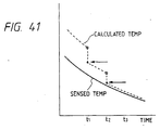
- Fig. 21 is a graph for describing the sixth example. In this case, unejection is decided using the monitor temperature of the head and the presumed temperature of the head immediately after printing of one scan and shortly before starting next printing.
- T1 is a monitor temperature of the head immediately after printing of one scan has been finished
- T2 is a presumed temperature of the head immediately after printing of one scan has been finished
- T3 is a monitor temperature shortly before printing of next scan is started
- T4 is a presumed temperature shortly before printing of next scan is started.
- a result obtained by subtracting a value, which is obtained by subtracting the presumed temperature of the head from the monitor temperature of the head shortly before printing of next scan is started, from a value, which is obtained by subtracting the presumed temperature of the head from the monitor temperature of the head immediately after printing of one scan has been finished is referred to as ⁇ T. If ⁇ T is larger than the threshold value ⁇ Tth after unejection has been detected in comparison, it is decided that the head is in the state of unejection.
- the monitor temperature of the head becomes far higher than the presumed temperature of the head and similarly becomes far lower than the presumed temperature after printing, and therefore ⁇ T becomes large. If ejection of the recording head is normal, a difference between the monitor temperature of the recording head and the presumed value of the recording head temperature is small and therefore ⁇ T is small.
- the threshold value ⁇ Tth for decision is set to be as large as a faulty operation due to noise can be eliminated and t be as small as unejection can be certainly decided.
- a merit of this example is found in a point that a monitor temperature of the head when printing is not carried out is used.
- signals generated during printing include a noise due to printing.
- the signals include noises due to printing by other heads in parallel connection.
- unejection of the recording head can be decided in higher accuracy.
- unejection is detected in each scan.
- unejection of the recording head can be decided by accumulating ⁇ T of, for example, several scans.
- a value obtained by subtracting the presumed value of the head temperature from the monitor temperature of the head is accumulated during idle ejection under a non-printing condition.
- the recording apparatus used in the second example is used, and head temperature monitor means, head temperature presuming means and ejection recovery means are the same as in the first example.
- an ink jet recording apparatus In an ink jet recording apparatus according to this example, a specified number of times of idle ejection is carried out before printing of one page is started. Unejection of the recording head is decided by utilizing this operation.
- unejection of the recording head is decided in accordance with variations of the temperature of the recording head along with idle ejection, talking into account a possibility of deciding the ejection as a faulty ejection due to a rarely sudden noise from outside the recording apparatus, and the unejection is finally decided.
- the unejection is finally decided by a method in which the recording apparatus optically detects unejection of the recording head during idle printing.
- a light of, for example, an light emission diode is passed through a part where droplets of ink ejected from the recording head during idle ejection are received and this light is received by a light receiving element.
- the unejection is decided by detecting the light which will be interrupted by a droplet of ink during idle ejection.
- the first to eighth examples which are included for illustrative purposes only and do not fall within the scope of the invention claimed enable to monitor an excessive rise of temperature.
- the durability of the recording head can be improved and the reliability of the ink jet recording apparatus can be enhanced by various effective measures such as ejection recovery treatment of the recording head from abnormalities, protective treatment for the recording head and warning and recommendation for users.
- An apparatus of this embodiment can adopt the same structure as that of the first example.
- the operation of ejection and the amount of ejection can be stabilized and the impartation of high quality to images to be recorded can be attained by controlling the temperatures of the recording heads within a fixed range.
- the means for computation and detection of the temperatures of the recording heads and the method for controlling the optimum drives for such temperatures which are adopted in the present example for the purpose of realizing stable recording of images of high quality will be outllned below.
- Fig. 24 is a view for explaining divided pulses according to this embodiment of the present invention.
- V OP represents an operational voltage-
- P 1 represents the pulse width of the first pulse (to be referred to as a pre-heat pulse hereinafter) of a plurality of divided heat pulses
- P 2 represents an interval time
- P 3 represents the pulse width of the second pulse (to be referred to as a main-heat pulse hereinafter).
- T1, T2 and T3 represent times for determining the pulse widths P 1 , P 2 , and P 3 .
- the operational voltage V OP represents electrical energy necessary for causing an electrothermal converting element applied with this voltage to generate heat energy in the ink in an ink channel constituted by the heater board and the top plate. The value of this voltage is determined by the area, resistance, and film structure of the electrothermal converting element, and the channel structure of the recording head.
- the PWM control of this embodiment can also be referred to as a divided pulse width modulation driving method.
- the pulses respectively having the widths P 1 , P 2 , and P 3 are sequentially applied.
- the pre-heat pulse is a pulse for mainly controlling the ink temperature in the channel, and plays an important role of the ejection quantity control of this embodiment.
- the pre-heat pulse width is preferably set to be a value, which does not cause a bubble production phenomenon in the ink by heat energy generated by the electrothermal converting element applied with this pulse.
- the interval time assures a time for protecting the pre-heat pulse and the main-heat pulse from interference, and for uniforming temperature distribution of the ink in the ink channel.
- the main-heat pulse produces a bubble in the ink in the ink channel, and ejects the ink from an ejection orifice.
- the width P 3 of the main-heat pulse is preferably determined by the area, resistance, and film structure of the electrothermal converting element, and the channel structure of the recording head.
- Figs. 25A and 25B are respectively a schematic longitudinal sectional view along an ink channel and a schematic front view showing an arrangement of a recording head which can adopt the present invention.
- an electrothermal converting element (ejection heater) 21 generates heat upon application of the divided pulses.
- the electrothermal converting element 21 is arranged on a heater board together with an electrode wire for applying the divided pulses to the element 21.
- the heater board is formed of a silicon layer 29, and is supported by an aluminum plate 31 constituting the substrate of the recording head.
- a top plate 32 is formed with grooves 35 for constituting ink channels 23, and the like.
- the ink channels 23, and a common ink chamber 25 for supplying the ink to the channels are constituted.
- Ejection orifices 27 are formed in the top plate 32, and communicate with the ink channels 23.
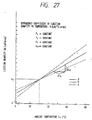
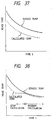
- Fig. 26 is a graph showing the pre-heat pulse dependency of the ejection quantity.
- the ejection quantity Vd is linearly increased according to anincrease in pre-heat pulse width P 1 , when the pulse width P 1 changes from 0 to P 1LMT .
- the change in quantity loses linearity when the pulse width P 1 falls within a range larger than P 1LMT .
- the ejection quantity Vd is saturated, i.e., becomes maximum at the pulse width p 1MAX .
- the range up to the pulse width P 1LMT where the change in ejection quantity Vd shows linearity with respect to the change in the pulse width P 1 is effective as a range where the ejection quantity can be easily controlled by changing the pulse width P 1 .
- P 1LMT 1.87 ( ⁇ s)
- V LMT 24.0 [pl/drop].
- the ejection quantity Vd becomes smaller than V MAX .
- This phenomenon produces a small bubble (in a state immediately before film boiling) on the electrothermal converting element upon application of the pre-heat pulse having the pulse width within the above-mentioned range, the next main-heat pulse is applied before this bubble disappears, and the small bubble disturbs bubble production by the main-heat pulse, thus decreasing the ejection quantity.
- This region is called a pre-bubble production region. In this region, it is difficult to perform ejection quantity control using the pre-heat pulse as a medium.
- the ink temperature of the ejection unit (which may often be substituted with the temperature of the recording head) is known.
- This coefficient KT is determined by the head structure, the ink physical property, and the like independently of the driving condition.
- curves b and c also represent the cases of other recording heads.
- KT 0.3 [pl/°C ⁇ drop].
- the pulse can be multi-pulses such as, for example, triple pulses and the control can be a main pulse PWM drive system for which the width of the main pulse is modulated with a single pulse.
- the drive is controlled so that the PWM value is primarily set from a difference ( ⁇ T) between the above-described target temperature and the head temperature.
- ⁇ T a difference between the above-described target temperature and the head temperature.
- temperature difference denotes the above ⁇ T
- preheat denotes the above P1
- interval denotes the above P2
- main denotes the above P3.
- setup time denotes a time until the above P1 actually rises after a recording instruction is entered. (This time is mainly an allowance time until the rise of the driver and is not a value which shares an principal factor of the present invention.)
- weight is a weight coefficient to be multiplied with the number of print dots to be detected to calculate the head temperature. In printing the same number of print dots, there will be a difference in the rise of head temperature between printing in the pulse width of 7 ⁇ s and printing in the pulse width of 4.5 ⁇ s. The above "weight” is used as means for compensating the difference of temperature rises along with modulation of the pulse width according to which PWM table is selected.
- This embodiment adopts the same temperature prediction control as that of the first embodiment, and the description thereof will be omitted.
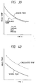
- Figs. 29A and 29B show the comparison of an actually sensed recording head temperature and a recording head temperature presumed by a head temperature calculation means by using the recording head structure described in the first embodiment.
- Figs. 29A and 29B where, the horizontal axis; elapse time (sec), the vertical axis; temperature rise ( ⁇ temp), print pattern; (25%Duty*5Line + 50%Duty*5Line + 100%Duty*5Line) * 5 times (print totals 75 lines)
- Figs. 29A and 29B a fact that the head temperature can be accurately presumed by the calculation means is assured.
- the measurement shown in Fig. 29B was performed by using temperature sensors in the recording head after noticeable electrostatic steps are given.
- the scatter in the heat characteristic of the recording head causes various types of heads may be manufactured, which are different from each other, e.g., different in the ejection quantity by the scattering in manufacturing of the recording head, different in the released heat characteristic or in the heat conduction by the scattering of members (adhesive layer, and the like).
- the recording head is modeled by a smaller number of thermal time constants than that in practice, thus leading to errors. Since it is difficult for the calculated head temperature to correspond to entire heads, the case of using a certain head, as a result, may lead to an error between the sensed head temperature and the calculated head temperature. Furthermore, the error is increased in increase of the number of recording paper sheets, thus leading to a noticeable error.
- the calculated head temperature is corrected at a predetermined timing.
- En E BASE + ⁇ temp
- the temperature sensors can not sense the temperature of the recording head by noise generated by driving the ejection heater, the temperature control heater and the like. Therefore, the temperature of the recording head is sensed in the temperature sensors by using the ejection heater in which noise is relatively small, or when the temperature control heater is not driven, and then the error of the calculated temperature is corrected.
- Fig. 30 shows the relationship between the sensed temperature and the calculated temperature when the correction was performed.
- the calculated temperature is corrected by shifting the error quantity (Sn - En).
- a value sensed in the temperature sensors obtained when a power source turns ON is stored in a memory a value of an adopted base temperature of the first recording head, and is used by updating the value before starting print.
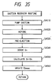
- Fig. 31 shows an interrupt routine for setting the PWM drive value and a sub-heater drive time for ejection.
- This interrupt routine occurs every 50 msec.
- the PWM value is always updated every 50 msec, regardless that the printing head is printing or idling and the drive of the sub-heater is necessary or unnecessary.
- S2010 the printing duty for 50 msec shortly before the interrupt.
- the printing duty to be referred to in this case is represented by a value obtained by multiplying the number of dots for which ink has been actually ejected by a weight coefficient for each PWM value as described in (PWM control).
- the temperature rise ( ⁇ Tmh) of a group of components for which the heat source is the ejection heater and the time constants are of a short range is calculated (S2020).
- the drive duty of the sub-heater for 50 msec is referred to (S2030)
- the temperature rise ( ⁇ Tsh) of a group of components for which the heat source is the ejection heater and the time constants are of a short range is calculated from the drive duty of the sub-motor for 50 msec and the drive history of the sub-heater for 0.8 seconds (S2040).
- the calculated temperature is obtained by adding temperature rise ⁇ temp and an adopted base temperature E BASE of the head (S2060).
- the adopted base temperature E BASE of the head is used as the updated one by a main routine described later.
- a target temperature is set by a target temperature table (S2070), calculating the temperature difference ( ⁇ T) between the head temperature and the target temperature (S2080). Then, a PWM value for an optimum head drive condition according to the head temperature is set by the temperature difference ⁇ T, and the PWM table, and the sub-heater table (S2090). Finally, the sub-heater is driven to keep the head temperature in the temperature control state.
- Fig. 32 shows a long range temperature rise calculation routine. This is a interrupt routine performed at the intervals of 1 sec, and the printing duty for the past one second is referred to (S3010).
- the printing duty is a value obtained by multiplying the number of dots for actual ejection by the weight coefficient for each PWM value as described in (PWM Control).
- a temperature rise ( ⁇ Tmb) of a group of components for which the heat source is the ejection heater and the time constants are of a long range is calculated from the printing history in the duty of one second and the past 512 seconds and stored as updated at a specified location of the memory (S3020) so that it can be easily referred to for the interrupt of every 50 msec.
- the drive duty of the sub-heater for one second is referred to (S3030), and a temperature rise ( ⁇ Tsb) of a group of components for which the heat source is the sub-heater and the time constants are of a long range is calculated from the printing history in the duty of one second and the past 512 seconds.
- ⁇ Tsb the temperature rise ⁇ Tsb calculated as above is stored as updated at a specified location of the memory so that it can be easily referred to for the interrupt of every 50 msec (S3040).
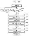
- Fig. 33 shows a operational flow for correcting the error between the calculated temperature and the sensed temperature of the recording head in this embodiment.
- a print sequence is performed. Firstly, the presence of a paper is checked (S4010), if no paper, a paper is fed (S4020). Next, the head temperature Sn is sensed by the temperature sensors provided in the recording head (S4030). On this time, since both the ejection heater and the sub-heater are not driven, the head temperature can be steadily sensed. The sensed temperature is compared with the calculated temperature to calculate the error (Sn - En) (S4040).
- the adopted base temperature is updated by adding the gap to the former adopted base temperature of the head ( old E BASE + (Sn - En) ), thus corresponding the sensed temperature to the calculated temperature (S4050).
- the calculated temperature is calculated by using the updated adopted base temperature. That is, if the head calculated temperature is lower than that in the temperature control state, head heating is performed (S4060), and the print is performed together with the ejection quantity control according to the PWM drive condition setting routine shown in Fig. 31 (S4070). After completing the print, the head heating is stopped (S4080), a recording medium (paper) is ejected (S4090), and the recording head returns in a waiting state.
- the correction of the gap between the calculated temperature and the sensed temperature can be performed by using the ejection heater in which the temperature sensors can steadily work, or when the sub (heating) heater is not driven.
- the gap is not converged to a certain condition even if the correction is performed by measuring the gap between the sensed temperature providing a slow response obtained by shifting average of plural times and the calculated temperature providing a sharp response.
- the gap is further enlarged.
- the gap it is preferable to correct the gap by performing the gap comparison of the sensed temperature and the calculated temperature after an interval (0.8 sec in this embodiment) until a short-range thermal past record in a small time constant at least disappears after stopping the ejection heater or sub-heater, more preferably, after the elapse of a few seconds.
- correction timing is set before starting the print, thus obtaining effects as follows:
- the correction may be effected in a predetermined time period after stop of supply of thermal energy, or repeated plural times for enhancement of precision.
- Fig. 34 shows a control structure for performing a recording control flow according to this embodiment.
- a CPU 60 is connected to a program ROM 61 for storing a control program executed by the CPU 60, and a backup RAM 62 for storing various data.
- the CPU 60 is also connected to a main scan motor 63 for scanning the recording head, and a sub-scan motor 64 for feeding a recording sheet.
- the sub-scan motor 64 is also used in the suction operation by the pump.
- the CPU 60 is also connected to a wiping solenoid 65, a paper feed solenoid 66 used in paper feed control, a cooling fan 67, and a paper width detector LED 68 which is turned on in a paper width detection operation.
- the CPU 60 is also connected to a paper width sensor 69, a paper flit sensor 70, a paper feed sensor 71, an paper eject sensor 72, and a suction pump position sensor 73 for detecting the position of the suction pump.
- the CPU 60 is also connected to a carriage HP sensor 74 for detecting the home position of the carriage, a door open sensor 75 for detecting an open/closed state of a door, and a temperature sensor 76 for detecting the surrounding temperature.
- the CPU 60 is also connected to a gate array 78 for performing supply control of recording data to the four color heads, a head driver 79 for driving the heads, the ink cartridges 8a for four colors, and the recording heads 8b.
- Fig. 34 representatively illustrates the Bk (black) ink cartridge 8a and the Bk recording head 8b.
- the ink cartridge 8a has a remaking ink sensor 81 for detecting a residual quantity of the ink.
- the head 8b has main heaters 8c for ejecting the ink, sub-heaters 8d for performing temperature control of the head, and temperature sensors 8e for detecting the head temperature.
- Fig. 34 recording signals, and the like sent through an external interface are stored in a reception buffer 78a in the gate array 78.
- the data stored in the reception buffer 78a is developed to a binary signal (0,1) indicating "to eject/not to eject", and the binary signal is transferred to a print buffer 78b.
- the CPU 60 can refer to the recording signals from the print buffer 78b as needed.
- Two line duty buffers 78c are prepared in the gate array 78.
- Each line duty buffer stores print duties (rations) of areas obtained by dividing one line at equal intervals (into, e.g., 35 areas).
- the "line duty buffer 78c1" stores print duty data of the areas of a currently printed line.
- the “line duty buffer 78c2” stores print duty data of the areas of a line next to the currently printed line.
- the CPU 60 can refer to the print duties of the currently printed line and the next line any time, as needed.
- the CPU 60 refers to the line duty buffers 78c during the above-mentioned temperature prediction control to obtain the print duties of the areas. Therefore, the calculation load on the CPU 60 can be reduced.
- the PWM of a double-pulse, or a single-pulse is used for controlling the ejection quantity and the head temperature
- a PWM of a triple-pulse may be used.
- a head chip temperature is higher than the print target temperature and can not be fallen in spite of being driven by a PWM providing small energy
- a scan speed, or a scan starting timing of the carriage may be controlled.
- This embodiment is not required to provide complete electrostatic steps, and can properly correct the error between the sensed temperature and the calculated temperature by using the temperature sensors without accumulating the gap of the calculated temperature even if any recording heads having various types of heat characteristics are used. Therefore, since an accurate temperature detection having a good response quality is obtained, various types of head controls can be performed before actual print, thus performing more suitable recording. Furthermore, the model is simplified, and the calculation algorithm is an accumulation of easy calculations, thus also simplifying the prediction control.
- Each constant used in this embodiment e.g., a cycle of temperature prediction (50 msec intervals, and 1 sec intervals) and the like, is an example, and the present invention is not limited to those constants.
- the adopted base temperature of the recording head was updated by adding the error quantity (Sn - En) to the adopted base temperature of the recording head (E BASE)
- the adopted base temperature can be updated by multiplying the error quantity (Sn - En) by an experiential coefficient ⁇ ( ⁇ 1) to prevent an excessive correction as shown the following formula.
- E BASE (new) E BASE (old) + ⁇ (Sn - En)
- the present invention is not limited to this embodiment.
- the present invention can be further effective in a color ink jet recording apparatus providing with a plurality of recording heads, because, in the ink jet recording apparatus having a plurality of recording heads, the sensed temperature becomes higher than the calculated temperature by conducted heat from other recording heads. As the number of recording heads increases, it is difficult to calculate conducted heat of various types, and the accumulation of errors also becomes large. Therefore, if the adopted base temperature of the recording head is updated by the above-mentioned method before print recording, the errors can be reduced and the accurate head control can be obtained.
- the error of the head calculated temperature is also led during the suction recovery operation using a suction pump. Since the ink pumped up through a nozzle of the recording head takes heat away, the recording head is subject to the temperature change.
- the change quantity is changeable by differences of the ink temperature or the pumped ink quantity, and it is difficult to predict.
- Fig. 35 shows a correction flow of a calculated temperature according to this embodiment.
- a carriage is transferred to the home position for capping the recording head, and the suction of the recording head is performed by a suction means communicated with a cap (S4510).
- a suction orifice surface of the recording head is wiped by a cleaning blade (S4520), pre-ejection is performed (S4530).
- the head temperature Sn is sensed by a temperature sensor provided in the recording head (S4540). Since the suction recovery operation requires more than a few seconds, and both an ejection heater and a sub-heater are not in a driving state on this moment, the temperature sensor can be steadily sensed.
- the temperature sensed by the sensor is compared with the calculated temperature, and the error is calculated (S4550).
- the adopted base temperature is updated by adding the gap to the adopted base temperature, and the sensed temperature and the calculated temperature are corresponded to each other (S4560). After that, the calculated temperature is calculated by using the updated adopted base temperature. Therefore, even if the suction recovery operation is performed during the print recording, the print recording can be performed again after the temperature change generated by the ink suction, so that the head driving control can be obtained by further accurate calculated temperature.
- an ink slip check operation of whether the ink is filled in a ink chamber of the head heating or recording head, and the like may be inserted.
- the ink slip detection performs a predetermined number of ink ejection (pre-ejection) and then, senses temperature rise. If the ink is filled in the ink chamber, temperature rise appearers within a threshold. On the other hand, if the ink is not filled in the ink chamber, temperature rise appears over the threshold. In this manner, the ink slip is detected by sensing temperature rise. That is, lack of ink causes an error between the sensed temperature and the calculated temperature because of differences of stored heat quantities therebetween, so that it can be effective to correct the error between the sensed temperature and the calculated temperature after the ink slip detection.
- Fig. 36 is a schematic diagram of an ink jet recording apparatus applied in the present invention.
- ink jet cartridges C respectively have ink tank portions in the upper side thereof and recording head portions in the lower side thereof, and respectively provide connectors for receiving signals which drive the recording heads.
- a carriage 12 locates and arranges four cartridges C1, C2, C3 and C4 (each cartridges is filled with different color, such as black, cyan, magenta and yellow).
- the carriage 12 provides a connector holder for transmitting signals and the like, which drive the recording heads, and is electrically connected with the recording heads.
- a scan rail 11 is extended in the main scan direction of the carriage 12, and supports the carriage 12 which is slidable therefor.
- a driving belt 52 transmits driving force to the carriage 12 for reciprocating motion.
- a pair of carrier rollers 15,16 and 17, 18 hold and carry a recording medium P arranged across the recording position of the recording heads.
- the recording medium P such as a paper sheet is pressed against a platen (not shown) for controlling the recorded surface of the recording medium to be plane.
- the recording portions of the ink jet cartridges C arranged on the carriage 12 is jutted downward from the carriage 12, is located between the recording medium carrier rollers 16 and 18.
- a recovery system unit is set to the home position side shown in the right hand side of Fig. 36.
- cap units 300 respectively correspond to a plurality of ink jet cartridges C having the recording heads, which is slidable in the right and left sides of Fig. 36 in response to movement of the carriage 12, and also movable in the upper and lower sides.
- a pump unit 500 communicates with the cap units 300 in the recovery system unit. If the recording heads should be subjected to poor ejection, the pump unit 500 is used for generating the negative pressure in case of the suction recovery operation which is performed by joining the cap units 300 and the recording heads.
- a blade 401 is formed of an elastic material such as rubber as a wiping member, and a blade holder 402 holds the blade 401.
- the cartridges C1, C2, C3 and C4 is respectively filled with a black (to be abbreviated to as K hereinafter) ink, a cyan (to be abbreviated to as C hereinafter) ink, a magenta (to be abbreviated to as M hereinafter) ink, and a yellow (to be abbreviated to as Y hereinafter) ink.
- K black
- C cyan
- M magenta
- Y yellow
- the inks overlap each other in this order.
- Intermediate colors can be realized by properly overlapping C, M, and Y color ink dots. More specifically, red can be realized by overlapping M and Y: blue, C and M; and green, C and Y. Black can be realized by overlapping three colors C, M and Y.
- each heat characteristic of the heads is sensed.
- each heat characteristic of the heads is sensed at the time of exchange.
- the main body of the recording apparatus has an ejection heater and a calculation table (temperature reduction data) for the sub-heater for temperature calculation.
- This calculation table contains temperature changes of the recording head at a constant interval of time (way of heat transmission as viewed from a Di sensor).
- the way of joining between members of a recording head, an ejection quantity, a dispersion in a main unit power supply for heater drive, etc. cause the contents of the calculation table to vary for each recording head. Therefore, temperature data of the recording heads, which are different in the heat conduction, are sensed, and calculation tables for the ejection heater and sub-heater are prepared in every temperature data.
- temperature changes are divided into three patterns for easy-to-accumulate-heat recording heads through hard-to-accumulate-heat heads, and corresponding three calculation tables mentioned above are provided.
- a center table 2 indicative of central conduction of heat for recording heads is provided between a large-temperature-change table 3 (easy to accumulate heat) and a small-temperature-change table 1 (hard to accumulate heat).
- Measurement of sub-heater thermal characteristics is intended to select a table.
- a duty (energy) decided in advance is input to the ejection heater and sub-heater.
- the temperature change of the Di sensor obtained on this moment is sensed before and after inputting such energy.
- the value of the temperature change is compared with a predetermined threshold.
- a measurement value will be greater than a threshold 2; hence, the large-temperature-change table 3 is selected as a calculation table.
- the small-temperature-change table 1 is selected on the assumption that a head is hard to accumulate heat.
- the center table 2 is selected on the assumption that a head is a standard recording head.
- the difference between the sensed temperature and the calculated temperature of the recording head, which is caused by scattering in the heat characteristic during driving the ejection heater and sub-heater, can be reduced from start.
- the temperature sensors can not sense the temperature of the recording head by noise generated by driving the ejection heater, the temperature control heater and the like. Therefore, the temperature of the recording head is sensed in the temperature sensors by using the ejection heater in which noise is relatively small, or when the temperature control heater is not driven, and then the error of the calculated temperature is corrected.
- the correction of the error in the calculated temperature is performed to the update adopted base temperature by adding the error quantity (Sn - En) to the adopted base temperature (E BASE).
- E BASE (new) E BASE (old) + (Sn - En)
- the correction can be performed at timings before starting the print recording and after completing the recovery operation.
- This embodiment shows another correction method for detecting a calculated temperature.
- the first and the second embodiments correct the calculated temperature by adding the error quantity to the adopted base temperature E BASE, this embodiment corrects the calculated temperature by processing temperature rise. (Case of Sensed Temperature > Calculated Temperature)
- Figs. 37 and 38 the calculated temperature is lower than the sensed temperature, Fig. 37 shows a case that the correction processes are not performed, and Fig. 38 shows a case that the correction processes are performed.
- a gap error
- the error affects later sequence. Therefore, when the recording is not performed (during not driving both the ejection heater and sub-heater), the calculation of the head temperature is stopped on the way to calculation until the sensed temperature is reduced as shown in Fig. 38. Then, the calculation of the head temperature is restarted after the difference between the sensed temperature and the calculated temperature becomes within a predetermined value (e.g., within ⁇ 1 deg).
- a virtual print duty can be added instead of an actual print until the difference between the sensed temperature and the calculated temperature becomes within a predetermined value.
- the virtual print duty may be set to be changeable according to the difference in temperature, and only the long range quantity of the virtual print duty may be added, without adding the short range one.
- the calculated temperature is higher than the sensed temperature
- Fig. 40 shows a case that the correction processes are not performed
- Fig. 41 shows a case that the correction processes are performed.
- This case brings the calculated temperature close to the sensed temperature by pre-shift (skip) calculation of the calculated temperature, and the operation is performed until the difference between the sensed temperature and the calculated temperature becomes within a predetermined value. That is, the calculation is skipped, e.g., where the calculated temperature at time t1 is set as the calculated temperature at time t2, and the calculated temperature at time t2 is set as the calculated temperature at time t3.
- the skip quantity may be changed according to the difference in temperature to accelerate the correction.
- the recording head temperature is presumed by calculating the recording head temperature against the input energy supplied for the calculation. Then, the sensed temperature is referred before print recording start and/or after recovery operation completion, in which the recording head is thermally in a steady state to be detected. The accumulation of errors is, finally, prevented by properly correcting the gap between the calculated temperature and the actually sensed head temperature.
- the ink jet recording apparatus in which the driving control for steadily performing ejection of the recording head by using the highly accurate calculated temperature, call be realized without complete electrostatic steps given to the temperature sensors provided in the recording head.
- the present invention is usable in an ink jet recording head and recording apparatus wherein thermal energy by an electrothermal transducer, laser beam or the like is used to cause a change of state of the ink to eject or discharge the ink. This is because the high density of the picture elements and the high resolution of the recording are possible.
- the typical structure and the operatidnal principle are preferably the ones disclosed in U.S. Patent Nos. 4,723,129 and 4,740,796.
- the principle and structure are applicable to a so-called on-demand type recording system and a continuous type recording system. Particularly, however, it is suitable for the on-demand type because the principle is such that at least one driving signal is applied to an electrothermal transducer disposed on a liquid (ink) retaining sheet or liquid passage, the driving signal being enough to provide such a quick temperature rise beyond a departure from uncleation boiling point, by which the thermal energy is provided by the electrothermal transducer to produce film boiling on the heating portion of the recording head, whereby a bubble can be formed in the liquid (ink) corresponding to each of the driving signals.
- the liquid (ink) is ejected through an ejection outlet to produce at least one droplet.
- the driving signal is preferably in the form of a pulse, because the development and contraction of the bubble can be effected instantaneously, and therefore, the liquid (ink) is ejected with quick response.
- the driving signal in the form of the pulse is preferably such as disclosed in U.S. Patents Nos. 4,463,359 and 4,345,262.
- the temperature increasing rate of the heating surface is preferably such as disclosed in U.S. Patent No. 4,313,124.
- the structure of the recording head may be as shown in U.S. Patent Nos. 4,558,333 and 4,459,600 wherein the heating portion is disposed at a bent portion, as well as the structure of the combination of the ejection outlet, liquid passage and the electrothermal transducer as disclosed in the above-mentioned patents.
- the present invention is applicable to the structure disclosed in Japanese Laid-Open Patent Application No. 59-123670 wherein a common slit is used as the ejection outlet for plural electrothermal transducers, and to the structure disclosed in Japanese Laid-Open Patent Application No. 59-138461 wherein an opening for absorbing pressure wave of the thermal energy is formed corresponding to the ejecting portion. This is because the present invention is effective to perform the recording operation with certainty and at high efficiency irrespective of the type of the recording head.
- the present invention is effectively applicable to a so-called full-line type recording head having a length corresponding to the maximum recording width.
- a recording head may comprise a single recording head and plural recording head combined to cover the maximum width.
- the present invention is applicable to a serial type recording head wherein the recording head is fixed on the main assembly, to a replaceable chip type recording head which is connected electrically with the main apparatus and can be supplied with the ink when it is mounted in the main assembly, or to a cartridge type recording head having an integral ink container.
- the provisions of the recovery means and/or the auxiliary means for the preliminary operation are preferable, because they can further stabilize the effects of the present invention.
- preliminary heating means which may be the electrothermal transducer, an additional heating element or a combination thereof.
- means for effecting preliminary ejection (not for the recording operation) can stabilize the recording operation.
- the recording head mountable may be a single corresponding to a single color ink, or may be plural corresponding to the plurality of ink materials having different recording color or density.
- the present invention is effectively applicable to an apparatus having at least one of a monochromatic mode mainly with black, a multi-color mode with different color ink materials and/or a full-color mode using the mixture of the colors, which may be an integrally formed recording unit or a combination of plural recording heads.
- the ink has been liquid. It may be, however, an ink material which is solidified below the room temperature but liquefied at the room temperature. Since the ink is controlled within the temperature not lower than 30°C and not higher than 70°C to stabilize the viscosity of the ink to provide the stabilized ejection in usual recording apparatus of this type, the ink may be such that it is liquid within the temperature range when the recording signal is the present invention is applicable to other types of ink. In one of them, the temperature rise due to the thermal energy is positively prevented by consuming it for the state change of the ink from the solid state to the liquid state. Another ink material is solidified when it is left, to prevent the evaporation of the ink.
- the ink is liquefied, and the liquefied ink may be ejected.
- Another ink material may start to be solidified at the time when it reaches the recording material.
- the present invention is also applicable to such an ink material as is liquefied by the application of the thermal energy.
- Such an ink material may be retained as a liquid or solid material in through holes or recesses formed in a porous sheet as disclosed in Japanese Laid-Open Patent Application No. 54-56847 and Japanese Laid-Open Patent Application No. 60-71260. The sheet is faced to the electrothermal transducers. The most effective one for the ink materials described above is the film boiling system.
- the ink jet recording apparatus may be used as an output terminal of an information processing apparatus such as computer or the like, as a copying apparatus combined with an image reader or the like, or as a facsimile machine having information sending and receiving functions.
Abstract
Description
- This invention relates to an ink jet recording apparatus and method which perform various controls using a presumed head temperature, more particularly, to ink jet recording apparatus and method in which stabilization of ink ejection and detection of ejection failure are effected by use of a presumed head temperature.
- Recording apparatus such as printers, copying machines and facsimile terminal equipment are constructed to record images consisting of dot-patterns onto recording materials such as plastic sheet.
- Recording apparatus can be classified into various types such as ink-jet, wire-dot, thermal, laser-beam etc., according to the recording method used.
- An ink-jet printer (ink-jet recording apparatus) is constructed to supply ink drops from an orifice or outlet of the recording head onto the recording material.
- Recently, a large number of recording apparatus have been used, and high-speed recording, high resolution, high-quality image low noise are required for these recording apparatus. The ink-jet recording apparatus can satisfy these requirements. As this ink-jet recording apparatus ejects ink from the recording head, the stabilization of both ink ejection and the amount of ejected ink that is required to fulfill the above requirements is greatly influenced by the ink temperature at the ink ejection orifice. If the ink temperature is too low, the viscosity of the ink will increase abnormally and the ink, will not be ejected by the normal ejection energy; if the temperature is too high, the ejected ink quantity will increase and the ink will overflow on the recording paper, leading to deterioration of the print quality.
- Therefore, in previous ink-Jet recording apparatus a method of controlling the ink temperature at the ejection opening to be within a desired range using a temperature sensor mounted on the recording head, or a method of controlling ink ejection recovery have been used. A heating element mounted on the recording head is used for said temperature control where the ink-jet recording apparatus is arranged to eject ink by using heat energy, i.e. in apparatus that ejects ink drops by bubble generation by ink film boiling, the ejection heater Itself may be sometimes used for this purpose. To use the ejection heater as a temperature control heater the ejection heater must be supplied with electric current such that no bubble generation occurs. In recording apparatus in which ink drops are ejected by generating bubbles in solid or liquid ink by means of heat energy the ejection characteristics change greatly with recording head temperature. Therefore temperature control of the ink and of the recording head that substantially influences the ink temperature is particularly important.
- However when attempts are made to control the temperature accurately by means of a temperature sensor mounted on the recording head, the following problems can occur.
- First, there is the problem of measurement error in the temperature sensor. In representative temperature sensor types such as thermistors and thermocouples, resistance and electromotive force fluctuate according to temperature. When detecting these fluctuating values, electric noise can occur, and it is extremely difficult to suppress this noise completely.
- Secondly, there is the problem of cost, In order to detect said temperature in addition to the thyristers and thermoelements, amplifiers and antistatic components are needed and the antistatic components in particular lead to a considerable increase in costs.
- Particularly, in case of the recording apparatus having an exchangeable recording head, because the recording head is a consumable or replaceable part, the user detaches the head frequently from the recording apparatus. The power output of the temperature sensor goes from exchangeable recording head through a contact on the recording head carriage, and through the flexible wiring unchanged to the circuit on the print circuit board in the main body of the apparatus. Therefore the temperature measurement circuit can easily be influenced by electrostastic noise and, when operating the ejection heater or temperature regulating heater, noise occurs under the influence of driving pulses or temperature regulating current. Therefore without considerable antistatic measures, it is not possible to measure temperature exactly.
- As for temperature detection by the temperature sensor, in order to avoid detection errors, a method is used in which the average of several previously detected head temperatures is used as the present temperature. But by averaging the several detected temperatures, the dynamic temperature change at the recording head will be averaged, anda time delay will occur between the real temperature and the detected value (bad response), so that exact feedback control is not possible.
- For these reasons, a method in which the temperature fluctuation is calculated from the energy supplied to the recording head within a time unit has been suggested. However, this method has the following problems.
- First, in this method temperature fluctuation is calculated by accumulation of the hysterisis of the energy supplied to the recording head. Therefore an error can occur between the real head temperature and the calculated head temperature. In recording apparatus equipped with an exchangeable recording head there is also the problem of recording head differences. Different recording heads mounted on the recording apparatus may have varying ejection quantities and heat radiation characteristics due to manufacturing errors, and different heat transfer rates because of difference in elements (adhesive layer etc.). It is difficult to take these differences into consideration in the calculation of the head temperature. As a result, errors occur between the real head temperature and the calculated head temperature.
- The applicants suggest, in the Japanese Patent Publications Nos. 5-31906 (corresponding to U.S.S.N. 07/867,316, filed on April 10, 1992 and EP-A-0526223, 5-31918 (corresponding to U.S.S.N. 07/921,852, filed on July 30, 1992 and EP-0526223) and 5-64890 (corresponding to U.S.S.N. 07/852,671, filed on March 17, 1992 and to EP-A-0505154), solving these problems by correcting the temperature calculation using the detected temperature of the temperature detecting element in the recording head and a temperature presuming means.
- In Japanese Patent Publication No. 5-31906 a high measuring precision is achieved by correcting the values (tables etc.) used for the calculation using the difference between the temperature detected by temperature detecting means on the recording head in a thermally stable state and a presumed calculated temperature. In the Japanese Patent Laid-Open Application No. 5-31916 the correction of the temperature detecting means is conducted by means of ambient temperature detecting means contained in the recording apparatus which operate at times at which recording is not done, or at times at which the temperature does not change. In the Japanese Patent Publication No. 5-64890, the ratio of the temperature detected by the temperature detecting means to the calculated temperature is used to correct calculated temperature. These examples show methods to correct differences between individual temperature detecting means or differences of thermal time constants or thermal efficiencies at the time or ink-ejection between individual recording heads, all of which are problems of exchangeable recording heads.
- The temperature calculation method is to presume temperature behavior (rising temperature) by, for an object whose temperature has risen as a result of energy supplied within a time unit, presetting the degree by which the temperature of the object subsequently drops in each time unit, and by calculating the sum of said degrees to the present.
- In the above methods it is desirable for the throughput of the temperature presumption to be improved, and temperature calculation errors to be reduced.
- If an ink-jet recording head is left unused for a long time, increased ink viscosity, particularly in the ink channel near the ejection outlet, ink is not ejected normally and, when ink ejection occurs continuously in such cases as recording with relatively high printing duty is performed, small bubbles can grow in the ink in the ink channels during ejection, and bubbles remaining in the channels can influence the ejection, so that normal ejection is not possible. Besides the above mentioned bubbles that grow in accordance with the ejection, bubbles can enter the ink at joints in the ink supply lines.
- The above mentioned ejection failure can not only reduce the reliability of recording apparatus but can also damage the recording head itself and lead to a reduction of durability, because, when printing with high duty is performed by a recording head that cannot eject ink normally, the temperature at the recording head will rise to a significantly higher temperature than in the case where the recording head is in the normal state.
- As one of measures against ejection failure resulting from these various causes, the surface of the ejection opening on the recording head may be covered with a cap when ink is not being ejected to prevent increase of ink viscosity. As another means ink may be sucked from the ejection outlet while the head is capped so as to eject increased viscosity ink. As still another means, ejection recovery such as idle ejection in which ink is ejected into a certain ink sucking body consisting of an ink absorber etc may be used to discharge high viscosity ink.
- Such ejection recovery to prevent ejection failure is conducted automatically when the power is switched on, or at certain intervals during recording or by the user depressing a recovery button whenever necessary.
- But in ink-jet recording apparatus which performs ejection recovery at the power-on, if the user switches the power on and off frequently, the frequency of ejection recovery can increase unnecessarily and ink consumption and the quantity of ink sucked from the ejection outlet can increase. On the other hand, in recording apparatus in which the user operates the recovery button according to his own decision, the user cannot know if the recording head is in the normal state or not, unless the printing is actually performed. Therefore these types are not sufficiently reliable.
- In the Japanese Publication No. 4-255361 filed by the present applicants a technique is disclosed for deciding whether the recording head is in an ink ejectable failure state or not, according to a temperature rise at the recording head caused by idle ejection and a temperature fall occurring at the recording head after idle ejection (these measures will be hereinafter referred to as "ink failure detection").
- When power is switched on or after the elapse of a certain period of time after power switch on, ink failure detection is executed, and if the state of the recording head is determined to be an "ink failure state", ejection recovery is performed. By these measures unnecessary ejection recovery can be avoided, and ink consumption and waste ink can be reduced.
- However, in this method, it takes a certain time to detect ejection failure, and it is necessary to consume a considerable amount of ink. Where the detection of ejection failure is performed after the power is switched on, if the head enters the ink ejection failure state for some reason, and the user does not notice it, the recording apparatus would continue the printing operation, and the apparatus would be damaged by excessive rise of the recording head temperature.
- Particularly, for example, if an ink-jet recording apparatus in which the recording head is supplied with ink from an ink cartridge which the user replaces when it is empty, does not have the function of detecting when the ink cartridge is empty, the recording head will not be supplied with ink, and will enter the ink ejection failure state. Every time this situation occurs, the recording head will be in danger because of excessive temperature rise.
- EP-A-0505154 describes a thermal ink jet recording head temperature control wherein the head temperature is presumed front the surrounding temperature (using a sensor on a main PCB) and a table which determines an error from the surrounding temperature, and the supplied power (print duty ratio). EP-A-0505154 describes an ink jet recording apparatus wherein an operational temperature is predicted on the basis of a non-recording temperature and a print duty ratio.
- According to one aspect of the present invention, there is provided an ink jet recording apparatus in accordance with
claim 1. The present invention also provides an ink jet recording method in accordance withclaim 10. - An embodiment of the present invention provides an ink-jet recording apparatus in which the temperature on the recording head can be presumed with high precision, and a recording method therefor.
- An embodiment of the invention provides an ink-jet recording apparatus in which stabilization of ink ejection and detection of ink ejection failure can be performed very accurately, and a recording method therefor.
- An embodiment of the invention provides a recording apparatus in which information such as the characteristics of various recording heads can be measured exactly, and very accurate control can be achieved, and the startup time after the switching on power will be shortened, and a recording method therefor.
- An embodiment of this invention avoids wasting ink and maintains reliability by optimizing a recovery operation at the time when power is switched on.
- An embodiment avoids ink ejection failure (sometimes referred to herein as "unejection") by detecting the normal ejection very accurately.
- Embodiments of the present invention will now be described, by way of example, with reference to the accompanying drawings, in which:
- Fig. 1 is a perspective view of an ink-jet recording apparatus.
- Fig. 2 is a cross section of the cartridge shown in Fig. 1.
- Fig. 3 is a partial enlarged view of the head cartridge shown in Fig. 1.
- Fig. 4 is a diagram showing temperature rise characteristics of the recording head in the calculation of the recording head temperature,
- Fig. 5 is an equivalent circuit of the heat transfer of the modelled recording head in the calculation of the recording head temperature according to a first example included for illustrative purposes only and not falling within the scope of the invention claimed.
- Fig. 6 is a calculation table of short-range elements of the ejection heater in the calculation of the recording head temperature according to the first example.
- Fig. 7 is a calculation table of long-range elements of the ejection heater in the calculation of the recording head temperature according to the first example.
- Fig. 8 is a calculation cable of short-range elements of the sub-heater in the calculation of the recording head temperature according to the first example.
- Fig. 9 is a calculation table of long-range elements of the sub-heater in the calculation of the recording head temperature according to the first example.
- Figs 10A to 10C are the first diagrams to explain the unejection deciding means in the first example.
- Figs. 11A and 11B are the second diagrams to explain the ink ejection failure deciding means in the first example.
- Fig. 12 is a flowchart to explain the unejection deciding means in the first example.
- Fig. 13 is a schematic explanatory drawing of the ink-jet recording apparatus according to a second example included for illustrative purposes only and not falling within the scope of the invention claimed.
- Fig. 14 is a partial explanatory drawing of the recording head used in the second example.
- Figs. 15A to 15C are ideal printouts printed by an ink-jet recording apparatus.
- Figs. 16A to 16C are printouts printed by an ink-jet recording apparatus showing non-uniformity in the density.
- Figs. 17A to 17C are the first explanatory drawings showing non-uniformity reduction by means of divided recording method.
- Figs. 18A to 18C are the second explanatory drawings showing non-uniformity reduction by means of divided recording method.
- Fig. 19 is a flowchart to explain the unejection deciding means and the ink ejection failure recovery means in the second example.
- Fig. 20 is a flowchart to explain the ink ejection failure deciding means in a forth example included for illustrative purposes only and not falling within the scope of the invention claimed.
- Fig. 21 is a diagram to explain the ink ejection failure deciding means in a sixth example included for illustrative purposes only and not falling within the scope of the invention claimed.
- Fig. 22 is a table showing necessary calculation time interval and data hold time.
- Fig. 23 is a table of target temperatures applied for a first embodiment of the present invention.
- Fig . 24 is an explanatory drawing of the driving method for dividing pulse-width modulation.
- Figs. 25A and 25B are diagrams illustrating the constraction of a printing head.
- Fig. 26 is a diagram to explain the dependence of ejection on pre-heat pulse.
- Fig. 27 is a diagram showing temperature dependence of ejection quantity.
- Fig. 28 is a PWM table showing pulse width corresponding temperature differences between the target temperature and the head temperature.
- Figs. 29A and 20B are diagrams in which recording head temperature presumed by head temperature calculation means and measured head temperature are compared.
- Fig. 30 is a diagram to explain error correction for calculated temperature by head initial temperature in the first embodiment.
- Fig. 31 is a flowchart showing the interrupt routine for setting a PWM driving value.
- Fig. 32 is a fiowchart showing the interrupt routine for long-range temperature rise calculation.
- Fig. 33 is a flowchart showing error correction for presumed temperature in the first embodiment.
- Fig. 34 is a block diagram showing the control arrangement for executing the recording control flow.
- Fig. 35 is a flowchart showing error correction for presumed temperature in a second embodiment of the present invention.
- Fig. 36 is a perspective view illustrating the arrangement of the ink-jet recording apparatus applied for a third embodiment of the present invention.
- Figs. 37 to 41 are diagrams for explaining operations in a fourth embodiment of the present invention.
-
- An arrangement of a recording head in a preferable ink jet recording apparatus (IJRA) will be described below together with an operation of the recording head. Referring to a perspective view of Fig. 1, the operation of the recording apparatus will be briefly described. In Fig. 1, a recording head (IJH) 5012 is coupled to an ink tank (IT) 5001. As shown in Fig. 2, the
ink tank 5001 and therecording head 5012 form an exchangeable integrated cartridge (IJC). A carriage (HC) 5014 is used for mounting the cartridge (IJC) to a printer main body. Aguide 5003 scans the carriage in the sub-scan direction. - A
platen roller 5000 scans a print medium P in the main scan direction. Atemperature sensor 5024 measures the surrounding temperature in the apparatus. Thecarriage 5014 is connected to a printed circuit board (not shown) comprising an electrical circuit (thetemperature sensor 5024, and the like) for controlling the printer through a flexible cable (not shown) for supplying a signal pulse current and a head temperature control current which drive therecording head 5012 and a detected signal current given from a temperature detecting member. - The details of the ink jet recording apparatus IJRA with the above arrangement will be described below. In the recording apparatus IJRA, the carriage HC has a pin (not shown) to be engaged with a spiral groove 5004 of a
lead screw 5005, which is rotated through driving power transmission gears 5011 and 5009 in cooperation with the normal/reverse rotation of a drivingmotor 5013. The carriage HC can be reciprocally moved in directions of arrows a and b. Apaper pressing plate 5002 presses a paper sheet against theplaten roller 5000 across the carriage moving direction.Photocouplers lever 5006 of the carriage HC in a corresponding region and switching the rotating direction of themotor 5013. Amember 5016 supports acap member 5022 for capping the front surface of the recording head. A suction means 5015 draws the interior of the cap member by vacuum suction, and performs a suction recovery process of therecording head 5012 through anopening 5023 in the cap member. - A
cleaning blade 5017 is supported by amember 5019 to be movable in the back-and-forth direction. Thecleaning blade 5017 and themember 5019 are supported on a mainbody support plate 5018. The blade is not limited to this shape, and a known cleaning blade can be applied , as a matter of course. Alever 5012 is used for starting the suction operation in the suction recovery process, and is moved upon movement of acam 5020 to be engaged with the carriage HC. The movement control of thelever 5021 is made by a known transmission means such as a clutch switching means for transmitting the driving force from the driving motor. - The capping, cleaning, and suction recovery processes can be performed at corresponding positions upon operation of the
lead screw 5005 when the carriage HC reaches a home position region. This apparatus is not limited to this as long as desired operations are performed at known timings. - Fig. 2 shows the details of the
recording head 5012. Aheater board 5100 formed by a semiconductor manufacturing process is arranged on the upper surface of asupport member 5300. A temperature control heater (temperature rise heater) 5110, formed by the same semiconductor manufacturing process, for keeping and controlling the temperature of therecording head 5012, is arranged on theheater board 5100. Awiring board 5200 is arranged on thesupport member 5300, and is connected to thetemperature control heater 5110 and ejection (main)heaters 5113 through, e.g., bonding wires (not shown). Thetemperature control heater 5110 may be realized by adhering a heater member formed in a process different from that of theheater board 5100 to, e.g., thesupport member 5300. - A
bubble 5114 is produced by heating an ink by thecorresponding ejection heater 5113. Anink droplet 5115 is ejected from the correspondingnozzle portion 5029. The ink to be ejected flows from acommon ink chamber 5112 into the recording head. - Fig. 3 shows a preferred heater board of the recording head.
Temperature sensors, temperature control heaters and ejection heaters are arranged on the heater board. Fig. 3 is a schematic top plan view of the heater board. Temperature control (sub)heaters 8d, anejection portion line 8g on which ejection (main) heaters 8c is arranged, drivingelements 8h andtemperature sensors 8e are formed on the same board with the arrangement as shown in Fig. 3. A pair oftemperature sensors 8e are arranged on theSi board 853, respectively on the right and left sides of the line where a plurality of the ejection heaters 8c are arranged. A mean value of temperatures detected by the twotemperature sensors 8e is adopted as a detected temperature. By arranging each element on the same board, detection or control of a head temperature can be performed, and further, a compact head and a simplified manufacturing process of the recording head can be obtained. The sectional position of an outer surface wall of a top plate, which is separated into two areas, i.e., an area in which the heater board is filled with ink and another one in which the heater board is not filled with ink, is also shown in Fig. 3. - Next, a head temperature presuming means will be described below. The head temperature presuming means presumes the temperature of the recording head by connecting the temperature sensors, which sense the surrounding temperature in the apparatus, to the main body, detecting a change of the recording head in response to the surrounding temperature using calculation processing described below.
- The head temperature is presumed basically by using the following heat conduction formulas:
- In heating:
- In cooling started during heating:
- temp;
- increased temperature of object
- a;
- equilibrium temperature of object by heat source
- T;
- elapse time
- m;
- thermal time constant of object
- T1;
- time for which heat source is removed
- When the recording head is processed as a lumped constant system, the chip temperature of the recording head can be theoretically presumed by calculating the formulas (1) and (2) according to the print duty in correspondence with a plurality of thermal time constants.
- However, in general, it is difficult to perform the above-mentioned calculations without modifications in terms of a problem of the processing speed.
- Strictly speaking, all the constituting members have different time constant, and another time constant is formed between adjacent members, resulting in a huge number of times of calculations.
- In general, since an MPU cannot directly perform exponential calculations, approximate calculations must be performed, or calculations using a conversion table must be performed, thus disturbing a decrease in calculation time.
- The present inventors sampled data in the temperature rise process of the recording head by applying energy to the recording head with the above arrangement, and obtained the result shown in Fig. 4. Strictly speaking, the recording head with the above arrangement is constituted by combining many members having different heat conduction times. However, Fig. 4 reveals that such many heat conduction times can be processed as a heat conduction time of a single member in practice in ranges where the differential value of the function of the log-converted increased temperature data and the elapse time is constant (i.e., ranges A, B, and C having constant inclinations).
- From the above-mentioned result, in a model associated with heat conduction, the recording head processed using two thermal time constants. Note that the above-mentioned result indicates that feedback control can be more precisely performed upon modeling having three thermal time constants. However, it is determined that the inclinations in areas B and C in Fig. 4 are almost equal to each other, and the recording head is modeled using two thermal time constants in consideration of calculation efficiency. More specifically, one heat conduction is a model having a time constant at which the temperature is increased to the equilibrium temperature in 0.8 sec. (corresponding to the area A in Fig. 4), and the other heat conduction is given by a model having a time constant at which the temperature is increased to the equilibrium temperature in 512 sec. (i.e., a model of the areas B and C in Fig. 4).
- Furthermore, the recording head is processed as follows to obtain a model.
- The temperature distribution in heat conduction is assumed to be ignored, and entire recording head is processed as a lumped constant system.
- A heat source assumed to include two heat sources, i.e., a heat source for the print operation, and a heat source as sub-heaters.
- Fig. 5 shows a modelled heat conduction equivalent circuit. Fig. 5 illustrates only one heat source. However, when two heat sources are used, they may be connected in series with each other.
- In the head temperature calculations, the above-mentioned heat conduction formulas are developed as follows.
-
- Formula 〈2-n〉: equal to the temperature of the object at time nt when heating is performed from
time 0 to time nt, and the heat source is kept OFF from time t to time nt. - Formula 〈2-3〉: equal to the temperature of the object at time nt when heating is performed from time (n-3)t to time (n-2)t, and the heat source is kept OFF from time (n-2)t to time nt.
- Formula 〈2-2〉: equal to the temperature of the object at time nt when heating is performed from time (n-2)t to time (n-1)t, and the heat source is kept OFF from time (n-1)t to time nt.
- Formula 〈2-1〉: equal to the temperature of the object at time nt when heating is performed from time (n-1)t to time nt.
- The fact that the total of the above formulas are equal to the formula 〈1〉 has the following meaning. That is, a change in temperature (increase in temperature) of the
object 1 is calculated by obtaining a decreased temperature after an elapse of unit time from a temperature increased by energy supplied in unit time (corresponding to each of the formulas 〈2-1〉, 〈2-2〉, ......, 〈2-n〉), and a total sum of decreased temperatures at the present time from temperatures increased in respective past unit times is calculated to presume the current temperature of the object 1 (〈2-1〉+〈2-2〉+.....+〈2-n〉). - In this example 1, the chip temperature of the recording head is calculated (heat source * thermal time constant 2) four times based on the above-mentioned modeling. The required calculation times and data hold times for the four calculations are as shown in Fig. 22. Figs. 6 to 9 show calculation tables used for calculating the head temperature, and each comprising a two-dimensional matrix of input energy and elapse time. Fig. 6 shows a calculation table when ejection heaters are used as the heat source, and a member group having a short-range time constant is used; Fig. 7 shows a calculation table when ejection heaters are used as the heat source, and a member group having a long-range time constant is used; Fig. 8 shows a calculation table when sub-heaters are used as the heat source, and a member group having a short-range time constant is used; and Fig. 9 shows a calculation table when sub-heaters are used as the heat source, and a member group having a long-range time constant is used.
- As shown in Figs. 6 to 9, calculations are performed at 0.05-sec intervals to obtain:
- (1) an increase (in degrees) in temperature or a member having a time constant represented by the short range upon driving of the ejection heaters (ΔTmh);
- (2) an increase (in degrees) in temperature of a
member having a time constant represented by the short
range upon driving of the sub-heaters (ΔTsh);
calculations are performed at 1.0-sec intervals to obtain: - (3) an increase (in degrees) in temperature of a member having a time constant represented by the long range upon driving of the ejection heaters (ΔTmb); and
- (4) an increase (in degrees) in temperature of a member having a time constant represented by the long range upon driving of the sub-heaters (ΔTsb).
-
- The above-mentioned calculations are sequentially performed, and ΔTmh, ΔTsh, ΔTmb, and ΔTsb are added to each other (
- As described above, since the recording head constituted by combining a plurality of members having different heat conduction times is modeled to be substituted with a smaller number of thermal time constants than that in practice, the following effects can be obtained.
- As compared to a case wherein calculation processing is faithfully performed in units of all the members having different heat conduction times, and in units of thermal time constants between adjacent members, the calculation processing volume can be greatly decreased without impairing calculation precision so much.
- Since the head is modeled with reference to time constants, calculation processing can be performed in a small number of processing operations without impairing calculation precision. For example, in the above-mentioned case, when the head is not modeled in units of time constants, the calculation interval requires 50 msec since it is determined by the area A having a small time constant. On the other hand, the data hold time of discrete data requires 512 sec since it is decided by the areas B and C having a large time constant. More specifically, accumulation calculation processing of 10,240 data for last 512 sec must be performed at 50-msec intervals, resulting in the number of calculation processing operations several hundreds of times that of this embodiment.
- As described above, the temperature calculation algorithm processes temperature shift of the recording head as an accumulation of discrete values in an unit time, calculates the temperature shift in advance based on the corresponding discrete values within a range of energy which can be input, and tables the calculation result using the table constituted by a two-dimensional matrix of input energy and elapse time. The recording head constituted by combining a plurality of members having different heat conduction times is modeled to be substituted with a smaller number of thermal time constants than that in practice, and calculations are performed while grouping required calculation intervals and required data hold times in units of model units (thermal time constants). Furthermore, a plurality of heat source are set, temperature rise widths are calculated in units of model units for each heat source, and the calculated widths are added later to calculate the head temperature (plural heat source calculation algorithm), thus calculating entire temperature shift of the recording head upon calculation processing in an economical recording apparatus without providing a temperature sensor in the recording head.
- As an example for a head temperature monitoring means, this example monitors the head temperature by the
head temperature sensors 8e on the HB board shown in Fig. 3. When a noise level is high, processing operations for reducing the noise can be performed by, e.g., collecting outputs of the temperature sensors plural times and calculating the mean value of the recording head. - This example decides whether or not the recording head is in an unejection state according to the recording head temperature and the presumed temperature of the recording head obtained by using a presuming calculation. The condition of decision is as follows:
- Figs. 10A to 10C are graphs each showing a monitored recording head temperature (the mean value of four times), a presumed calculation value of the recording head and a value obtained by subtracting the presumed calculation value from the recording head temperature (hereinbelow, the value subtracting the presumed calculation value from the recording head temperature is called as ΔT). ΔT is over ΔTth as soon as unejection occurs, at this point, abnormal ejection is decided. The decision of whether the recording head is in an unejection state is performed in a constant time interval.
- When the abnormal ejection is decided, for example, ejection recovery processes may be performed immediately. In this example, taking into consideration that the abnormal ejection is decided by unexpected noises which uncommonly enter from the exterior of the recording apparatus, the following decision can be also performed. That is, the decision of whether or not the recording head is in an unejection state is certainly performed by measuring temperature change quantities in both temperature rise and temperature reduction according to idle ejection as described in the background of the invention in the specification.
- As shown in Fig. 11A, temperature rise (T1 - T0) of the recording head during ejection in a predetermined time (t1 - t0) and temperature reduction (T1 - T2) of the recording head during unejection in a predetermined time (t2 - t1) after the elapse of the time (t1 - t0) are detected, if a total sum of these temperatures
- Fig 12 is a flow chart of the decision of unejection. A head temperature is sensed by sensors at step S110, a presumed value of the head temperature is calculated at step S120 and ΔT and ΔTth are compared with each other at step S130 (first decision A mode shown in Fig. 11B). Even if an unejection state is decided, for performing further certain decision, the unejection state is decided again by measuring temperature rise and temperature reduction at step S140 (final decision B mode shown in Fig. 11B).
- The unejection state is decided by using differences in temperature of both temperature rise and temperature reduction as shown above, thus certainly detecting unjection even if the recording head is slightly in a temperature reduction state. If the unejection state of the recording head is decided only when the recording head has few temperature changes, it can be decided by using only one difference in temperature of either temperature rise or temperature reduction.
- When the recording head is decided to be in the unejection state at step S140, suction recovery processes are performed at step S150. After that, the recording head is decided again to be in the unejection state by measuring temperature change quantities in both temperature rise and temperature reduction according to idle ejection, checking whether or not the recording head has returned in a normal state. If it is in a normal state, ejection recovery processes are completed. However, if it is in the unejection state in spite of suction recovery processes being done, error indication is performed to alarm to a user.
- In this method for detecting unejection when the print duty is low, temperature rise of the recording head naturally becomes small. However, even when the unejection state is not detected in spite of the recording head being in the unejection state, the recording head is protected from excessive temperature rise produced by unejection.
- In addition, examples considering the case that the print duty is low will be described from the third example below. In a second example included for illustrative purposes only and not falling within the scope of the invention claimed, ΔTth used for deciding the unejection can be changed according to the state of the recording apparatus. The head temperature presumption means and the head temperature monitoring means are the same as in the
embodiment 1. - Fig. 13 shows the construction of the recording part of the ink-jet recording apparatus used in the second example. In this Figure, 701 indicates the ink cartridges. These consist of ink tanks filled with color inks - black, cyan, magenta and yellow - and a multi-head 702. In Fig. 14 multi-nozzles arranged on the multi-head are shown from the z-direction. 801 indicates the multi-nozzles arranged on the multi-head 702. We shall go back to Fig. 13. 703 indicates a paper transport roller which rotates in the arrow direction depressing the printing paper together with the
axially roller 704, and transports the printing paper in the y-direction. 705 indicates a paper feed roller which feeds the printing paper and depresses the printing paper like 703 and 704. 706 is a carriage that supports and moves the 4 ink cartridges. This stays at the home position (h) indicated by dotted lines while the printing is not performed, or while the recovery procedure for the multi-head is being performed. - Before the printing is started, the carriage (706) which is standing at the position indicated in the drawing (home position) moves in the x direction, and performs the printing for the width L on the paper by n multi-nozzles of the multi-head (702). When the printing of the data to the end of the paper has been completed, the carriage returns to the home portion, and performs the printing in the x-direction again. By repeating the printing for the width L of the multi-head at each scanning of the carriage and the paper transport, the data printing on a sheet of paper is completed.
- But when the recording apparatus is not used as a monochrome printer for printing only characters, but is to be used to print images, various factors such as color development, tone, uniformity must be taken into consideration. Particularly as for the uniformity, slight differences of the nozzles caused in fabrication thereof can influence ink ejection quantity and ejection direction and deteriorate printing quality with uniformity in density.
- Concrete examples of ununiformity in density shall be shown by Figs. 15A to 15C and 16A to 16C. These were printed by a monochrome recording head in order to simplify the explanation. In Fig. 15A, 91 indicates the multi-head; the multi-head is similar to that in the Fig. 14, but it shall be assumed that it consists of 8 multi-nozzles (92) to simplify the explanation. 93 indicates ink droplets ejected by the multi-nozzle 92. It is ideal that the ejection take place in uniform quantity and in the uniform direction, as shown in this drawing. When the ejection is performed in this manner, uniform size of dots will drop on the paper (Fig. 15B), and a uniform image will be obtained (Fig. 15C).
- However, in reality, each nozzle is slightly different and if the printing would be performed as described above ink drops ejected through each nozzle will be not uniform in size and direction, as shown in the Fig. 16A, and the ink drops fall on the paper as shown in Fig. 16B. In this drawing head main scanning direction periodically blank spots that cannot fulfill the area factor of 100%, or conversely, dots are overlapping unnecessarily, or, as it can be seen in the middle of the drawing, white stripes. The clusters of dots fallen onto the paper form density distribution shown in Fig. 16C in the nozzle alignment direction. This is perceived by human eyes as ununiform density.
- In the ink-jet recording apparatus used in this example method which will be decribed below is adopted. This method shall be explained briefly using Figs. 17A to 17C and 18A to 18C. In this method, multi-head 91 must scan 3 times to complete printing the printing area shown in the Figs. 15A to 15C and 16A to 16C, whereas the area of 4 picture elements which corresponds to the half of the printing area can be completed by 2 passes. The 8 nozzles of the multi-head are divided into upper and lower group, each consisting of 4 nozzles; each nozzle prints at each scanning the dots that has been reduced to the half of the number of the dots in the original image data to a designated image data array (checker pattern shown in Fig. 18A). And at the second scanning the remaining half of the image data is filled with dots (reverse checker shown in Fig. 18B), and thus the printing in 4 picture elements is completed. This recording method is called divided recording.
- By using this recording method, specific influence of each nozzle on the printed image will be reduced by half, when the same multi-head as shown in Figs. 16A to 16C will be used; the printed images as shown in Fig. 17B will be obtained; black and white stripes as in Fig. 16B will be less apparent. Thus the ununiformity in the density will be, as shown in Fig. 17C, reduced considerably compared to Fig. 16C.
- In the recording apparatus used in the second example, when printing diagrams, the divided recording method in which the printing is performed in two scannings is adopted, and when printing texts in which ununiformity in the density is not very apparent, the printing can be performed in single scanning; in this printing mode higher printing speed can be achieved.
- In the second example, when printing in two scannings, a smaller ΔTth is chosen. And, by using the method of deciding unejection of the recording head by means of the temperature changes caused by temperature rise by idle ejection and temperature fall after the idle ejection simultaneously the reliability of the recording apparatus concerning the unejection shall be improved.
- In the recording apparatus used in this example comprising a plurality of heads arranged side by side, signals of head temperature sensor of other heads are disturbed by noises. It the printing duty is high, the noise that occur in the signals of the head temperature sensor of other heads will increase. Since in the printing mode in which the printing is conducted in two scannings the printing duty is low, the noise is also low, so the ΔTth can be set relatively narrow. As the printing duty is low, the temperature rise due to the printing will be little, and therefore it will be necessary to set the ΔTth narrow.
- It is also possible to find out the printing duty from the printing date beforehand, and to change ΔTth accordingly. For example, for each line the ΔTth can be set narrow when the printing duty is low, and it can be set wide when the printing duty is high.
- In this example the ΔTth is changed according to the different printing duties in various printing modes, hut noise level and the temperature rise due to the printing are not only influenced by printing duty. ΔTth may also be changed according to other factors, for example driving frequency of the recording head.
- The method that we showed as a hitherto technqiue, i.e. method to decide unejection of recording head by means of temperature change according to the temperature rise due to idle ejection and the temperature fall after the ejection can decide unejection of the recording head with certainty. But this method can be applied only when not printed, and it takes much time to execute the procedure, it can lead to reduction of throughput of the recording head if this method is frequently used. The method to decide unejection of the recording head using the monitored value and the presumed value of the head temperature described above is not confined to the times when not printed, and it has the advantage that throughput will be hardly reduced. But this method has the disadvantage that the recording head can malfunction by noises suddenly coming from outside, and, when the printing duty is low, it is difficult to decide unejection because ΔT is then narrow.
- For these reasons, in this example both of the unejection deciding method described above are adopted to improve the reliability of the recording apparatus concerning the unejection. Concretely, similar to the first example, considering the possibility that sudden noises from outside may lead to incorrect decision of unejection, the method to decide unejection of recording head by means of temperature change according to the temperature rise due to idle ejection and the temperature fall after the ejection is adopted to decide unejection of the recording head with certainty.
- When the power supplied for the recording head is switched on, decision of unejection of the recording head is conducted by means of the temperature change of the recording head due to idle ejection. If unejection of the recording head is detected, the ejection recovery measures may be performed. After elapsing of 60 hours after the switch on, the same sequence can be executed.
- The flowchart in the Fig. 19 illustrates the process of unejection detecting measures. Explanation of the part which is the same as in Fig. 12 shall be omitted. At Step S230 the printing mode of the recording head is obtained, and at step S240 the ΔTth corresponding to the printing mode is selected. In this example the printing mode of the recording apparatus is obtained before the decision of unejection, but this is not a necessary requirement. When the printing mode is changed by the user or by an application software, the ΔTth can also be changed according to the mode.
- In this example the ΔTth is changed according to the printing mode of the ink-jet recording apparatus, but the ΔTth can also be changed according to other states of the recording apparatus.
- For example, it is also advantageous to change the ΔTth according to the temperature difference between the recording head and the ambient temperature. The heat distribution in the recording head is different before starting the printing and after having performed high duty printing. In the former case, after starting the printing the heat generated by it is transferred quickly to other parts of the head having relatively low temperature compared to the part near the ejection heater. In the latter case, the temperature in other parts of the recording head has already become higher so that heat cannot be transferred easily. Therefore, it is adequate to set the ΔTth relatively high in the latter case.
- The ΔTth can also be changed according to the length of the time during which the recording apparatus has been left unused. If the recording head is left unused for a long time, volatile components of the ink in the vicinity of the election opening evaporate, and the viscosity of the ink increases so that the recording head cannot eject ink easily. If ink ejection (including pre-ejection) will be effected after leaving the apparatus unused for a long time, the ejection quantity is little, or no ejection can be performed at all. Since the ΔT will increase in this state, it is preferable to set ΔTth large.
- The ΔTth can also be changed according to the temperature difference between the monitored value and the presumed value of the head temperature. When the recording apparatus has stopped printing for a few seconds, the noise level decreases so that the monitored and presumed value of the recording apparatus should coincide. But if the monitored temperature differs from the presumed temperature due to the accuracy of the head temperature calculation, this difference will disturb the detection of unejection of the recording head. Therefore, it is effective for improving the accuracy of the decision of unejection to correct ΔTth according to the difference. Conversely, the same effect can be achieved by adjusting the presumed head temperature to the monitored head temperature when the recording apparatus is in a defined state.
- When the recording head is decided to be in the unejecting state at step S260, the suction recovery is executed at step S270. After that, the decision of unejection of the recording head by means of the temperature change due to idle ejection at step S280 in order to check if the normal state of the recording head has been recovered. If the state is normal, all the flags are reset (off) at step S290, and the suction recovery is completed. If the recording head is still in the unejection state in spite of the suction recovery, it is assumed chat the ink tank does not contain ink, and at step S300 error is displayed, and the apparatus waits for the operation by the user.
- When the user at step S310 replaces the head tank by a new tank containing ink, and depresses the suction recovery key, the suction recovery, and subsequently the decision of unejection is executed; when it is certified that the recording head is not in the unejection state, the normal state is recovered (The unejection flags will be explained later).
- If the user has depressed not the suction recovery key, but the on-line key, the normal state will be recovered by setting (on) the unejection flags at step S320, but the head decided to be in the unejected state will not be driven. In the present example, of the 4 unejection flags corresponding to 4 color-heads only the one which corresponds to the head decided to be in the unejection stage shall be switched on. Then the normal state will be recovered. After recovering the normal state, printing will be executed according to printing data, but the head corresponding to the unejection flag that is switched on will not be driven. Also the controls for printing by this head, such as temperature regulation, pre-ejection etc. will not be executed. The data corresponding the color of the head will he regarded as not existing, i.e., scanning of the carriage will not be executed if only the printing data for the color exist.
- These measures shall enable printing with remaining heads if the user desires, when one of the 4 color inks becomes empty. For example, when color inks of black, cyan, magenta and yellow are used, and in case a head tank containing one of these colors will be used up, it will be possible to perform monochrome printing using only the head for black ink. If the head not containing ink would also be driven, temperature would rise excessively, and the head would be damaged. (When the ink is emptied, the ink tank can be replaced in such apparatus in which ink tanks are replaceable, otherwise inks are to be refilled.) If the temperature will rise further the head tank will melt, and it will influence also the main body of the recording apparatus negatively.
- The ink-jet recording apparatus in this example is so controlled that scanning of areas not containing printing data will be avoided as far as possible. As the head decided to be in the state of unejection does not execute printing, throughput can be improved by ignoring the corresponding printing data.
- After power supply of the recording apparatus is switched on, when printing is to be started, the unejection flags are set (on), and the user will be warned by an error message. When the user has replaced the head tank by a new one filled with ink, (or has refilled the tank with ink), the suction recovery has been executed, and after the suction recovery the head is decided to be in the ejectable state, the unejection flag is reset (off).
- This sequence that enables printing without driving the head which is in the unejection state is effective, not only in the present example , but also generally in ink-jet recording apparatus which execute printing by ejecting inks of various colors, when one of the inks in the ink ejecting apparatus (in this example one of 4 colors) are used. This sequence is also effective, when a recording head is divided into several sections, and each section is driven separately (for example, if ink colors are different) and a part of the recording head has changed into the unejection state.
- In a third example included for illustrative purposes only and not falling within the scope of the invention claimed, a value obtained by subtracting a presumed temperature of the head from the monitor temperature of the head is accumulated for a period while unejection deciding means satisfies specified requirements. In this example, the recording apparatus used in the second example is used, and head temperature monitor means, head temperature presuming means and ejection recovery means are the same as in the first example.
- The monitor temperature of the head does not coincide with the presumed temperature of the head under a condition that unejection has not occurred. Probable causes in this case are, for example, presuming operation of the head temperature, deviation in software timing due to average processing of signals from the temperature sensor of the head, accuracy of presumption of the head temperature and various types of noises. Decision of unejection of the recording head according to a value obtained by subtracting a presumed temperature value of the head from the monitor temperature of the head results in a factor which will lower the accuracy of unejection decision.
- Therefore, in this example, a value obtained by subtracting the presumed temperature of the head from the monitor temperature of the head is accumulated at a specified interval of time. If a value obtained from accumulation for a specified period of time is larger than a specified threshold value ΔTth, it is decided that the recording head is in a state of unejection. Through accumulation for a specified period of time, the accuracy of decision of unejection can be raised and simultaneously an ejection failure can be detected even in low-duty printing.
- As described above, in this example, a value obtained by subtracting the presumed temperature of the head from the monitor temperature of the head is accumulated. However, even though the ejection of the recording head is normal, an accumulated value obtained by subtracting the presumed temperature of the head from the monitor temperature of the head may not be 0 (zero), depending on the accuracy of presuming operation. Therefore a difference of temperature values obtained after specified compensation for one of the monitor temperature of the head and the presumed temperature value of the head can be accumulated. With lapse of a certain specified time after accumulation of the monitor temperature value of the head and the presumed temperature value of the head, it can be decided from the result of accumulation as to whether the recording head is in the condition of unejection.
- In this example, a value obtained by subtracting the presumed temperature of the head from the monitor temperature of the head is accumulated for a specified period of time. The interval for accumulation is not limited to that specified time and can be, for example, a period of time for one scan.
- Ejection in this example includes ejection during printing but also pre-ejection during printing and pre-ejection before and after printing.
- In a fourth example included for illustrative purposes only and not falling within the scope of the invention claimed, the recording apparatus used in the second example is used, and head temperature monitor means, head temperature presuming means and ejection recovery means are the same as in the first example. Operation of this example is shown in the flow chart in Fig. 20. The description of the same components as shown in Fig. 19 is omitted.
- In the fourth example, a value (hereafter referred to as "ΔT") obtained by subtracting the presumed value of temperature of the head from the monitor temperature of the head is accumulated for a period of one scan. In step S430, a printing duty for one scan is obtained from printing data and the accumulated value is compensated by the value of the printing duty. In this example the number of characters per scan and a difference of the printing duty are compensated by dividing the accumulated value by the printing duty of one scan. If the printing duty of one scan is larger than the predetermined value (referred to as "Dth") and the compensated value is larger than the specified threshold value ΔTth, it is decided that the recording head is in the unejection state.
- A print area and a duty there printing is carried out in one scan differ with each scan. In comparison with the value ΔTth without compensation of the accumulated value of ΔT according to the printing duty, differing from the third example, the value ΔTth should be set to meet a case that the print area for one scan is large and the printing duty is also large, that is, the accumulated value of the printing duty for one scan is large. This is because, if the value ΔTth is set to meet a case that the accumulated value of the printing duty is small, ΔTth is relatively small and, if the accumulated value of the printing duty for one scan is large in actual printing it may be decided that the recording head is in a state of unejection despite that the recording head is normal.
- Therefore, this example is adapted to enable to detect unejection by compensation with the accumulated value for one scan of the printing duty even when the print area and the printing duty in one scan are smaller. The number of characters for each scan and the difference of the printing duty are compensated by dividing a value accumulated in step S470 by the printing duty of one scan.
- However, if the print area and the printing duty in one scan are small, ΔT is naturally small and the accumulated value of ΔT is also small. In this case, a value obtained by dividing the accumulated value of ΔT by the accumulated value of the printing duty substantially varies, depending on a noise included in the monitor temperature value of the head (noise level is high). This brings about a high possibility of faulty decision as to unejection. In step S460, if the accumulated value of the printing duty for one scan is smaller than the predetermined value Dth, it is decided that the noise level is high and therefore unejection is not decided.
- The above adaptive arrangement enhances the accuracy in detection of unejection of the recording head equivalent to or better than the third example and enables detection of unejection even in low duty printing.
- A value obtained by subtracting the presumed temperature of the head from the monitor temperature of the head is compensated by the printing duty for one scan. In addition, the threshold value ΔTth for deciding the ink dropping can be compensated by the printing duty for one scan. The period of accumulation is not always limited to a period of one scan. For example, the accumulation can be carried out for two scans.
- A value obtained by subtracting the presumed temperature of the head from the monitor temperature of the head is accumulated. However, an accumulated value obtained by subtracting the presumed temperature of the head from the monitor temperature of the head may not be 0 due to the accuracy of presuming operation even if the ejection of the recording head is normal. In this case, a difference of values obtained from specified compensation of one of the monitor temperature of the head and the presumed temperature of the head can be accumulated. Unejection of the recording head can be decided from an accumulated value when printing of one scan is finished after respective accumulations of the monitor temperature of the head and the presumed temperature of the head.
- In a fifth example included for illustrative purposes only and not falling within the scope of the invention claimed, the recording apparatus used in the second example is used, and head temperature monitor means, head temperature presuming means and ejection recovery means are the same as in the first example.
- In the fifth example, the number of print dots is obtained from printing data prior to actual printing. A value (hereafter referred to as "ΔT") obtained by subtracting the presumed temperature of the head from the monitor temperature of the head is accumulated and, at the same time, the number of print dots is counted. When the number of counted dots reaches a specified value, the accumulated value of ΔT is compared with the specified threshold value ΔTth for decision of unejection and, if the accumulated value of ΔT is larger than the value ΔTth, the recording head is decided as in the state of unejection.
- When the printing duty is high, ΔT when the recording head is in the state of unejection is sufficiently large and the duration of accumulation of ΔT for carrying out decision of unejection with high accuracy can be relatively less. When the printing duty is low, the duration of accumulation of ΔT, which is a small value, should be long to ensure accurate decision of unejection. In this example, the number of print dots is counted and accumulation of ΔT is carried out until the number of counted dots reaches the predetermined value. In the case of the printing duty of, for example, 100% and 50%, accumulation of ΔT in the printing duty of 50% is carried out for the number of print dots two times that in the printing duty of 100%.
- As in the third and fourth examples, the above-described arrangement enhances the accuracy in detection of unejection of the recording head and enables detection of unejection even in low duty printing.
- In this example, a value obtained by subtracting the presumed temperature of the head from the monitor temperature of the head is accumulated. However, an accumulated value obtained by subtracting the presumed temperature of the head from the monitor temperature of the head may not be 0 due to the accuracy of presuming operation even if the ejection of the recording head is normal. In this case, a difference of values obtained from specified compensation of one of the monitor temperature of the head and the presumed temperature of the head can be accumulated.
- The accumulation time in a relatively low printing duty is longer than that in a high printing duty, a quantity of heat which flows from the heater of the recording head and its ambiance to other parts of the recording head and the outside will increase while accumulation of ΔT is carried out. In some cases, it is considered that compensation in response to such thermal propagation should be implemented. For example, taking into account that, when the printing duty is relatively low, the accumulation time increases and accordingly the quantity of heat which flows from the heater and its ambiance of the recording head also relatively increases, and when the accumulation time of ΔT is short the ΔTth value can be set to be small.
- Ejection in this example may include ejection during printing but also pre-ejection during printing and pre-ejection before and after printing.
- In a sixth example included for illustrative purposes only and not falling with the scope of the invention claimed, the recording apparatus used in the second example is used, and head temperature monitor means, head temperature presuming means and ejection recovery means are the same as in the second example.
- Fig. 21 is a graph for describing the sixth example. In this case, unejection is decided using the monitor temperature of the head and the presumed temperature of the head immediately after printing of one scan and shortly before starting next printing. In Fig. 21, T1 is a monitor temperature of the head immediately after printing of one scan has been finished, T2 is a presumed temperature of the head immediately after printing of one scan has been finished, T3 is a monitor temperature shortly before printing of next scan is started, and T4 is a presumed temperature shortly before printing of next scan is started. A result obtained by subtracting a value, which is obtained by subtracting the presumed temperature of the head from the monitor temperature of the head shortly before printing of next scan is started, from a value, which is obtained by subtracting the presumed temperature of the head from the monitor temperature of the head immediately after printing of one scan has been finished is referred to as ΔT. If ΔT is larger than the threshold value ΔTth after unejection has been detected in comparison, it is decided that the head is in the state of unejection.
- If printing is carried out during unejection, the monitor temperature of the head becomes far higher than the presumed temperature of the head and similarly becomes far lower than the presumed temperature after printing, and therefore ΔT becomes large. If ejection of the recording head is normal, a difference between the monitor temperature of the recording head and the presumed value of the recording head temperature is small and therefore ΔT is small. The threshold value ΔTth for decision is set to be as large as a faulty operation due to noise can be eliminated and t be as small as unejection can be certainly decided.
- A merit of this example is found in a point that a monitor temperature of the head when printing is not carried out is used. Though not shown in Fig. 21, signals generated during printing include a noise due to printing. The signals include noises due to printing by other heads in parallel connection. In this example, unejection of the recording head can be decided in higher accuracy.
- In this example, unejection is detected in each scan. However, unejection of the recording head can be decided by accumulating ΔT of, for example, several scans.
- In a seventh example included for illustrative purposes only and not falling within the scope of the invention claimed, as unejection deciding means, a value obtained by subtracting the presumed value of the head temperature from the monitor temperature of the head is accumulated during idle ejection under a non-printing condition. In the seventh example, the recording apparatus used in the second example is used, and head temperature monitor means, head temperature presuming means and ejection recovery means are the same as in the first example.
- In an ink jet recording apparatus according to this example, a specified number of times of idle ejection is carried out before printing of one page is started. Unejection of the recording head is decided by utilizing this operation.
- Since idle ejection before starting the printing does not depend on the printing duty, there is a merit that unejection of the recording head can be decided even when the printing duty is low. In the case of high duty printing, unejection is detected during printing and, in the case of continuous low duty printing, it can be adapted to detect unejection of the recording head due to idle ejection by increasing the number of times of idle ejection before page printing.
- In an eighth example included for illustrative purposes only and not falling with the scope of the invention claimed, as in the first example, whether or not the recording head is in the state of unejection is decided from the monitor temperature of the recording head and the presumed temperature of the recording head obtained from the presuming operation. The ink jet recording apparatus, head temperature monitor means, head temperature presuming means and ejection recovery means which are used in this example are the same as in the first example.
- The conditions for decision of unejection are as follows.
- In the first example, unejection of the recording head is decided in accordance with variations of the temperature of the recording head along with idle ejection, talking into account a possibility of deciding the ejection as a faulty ejection due to a rarely sudden noise from outside the recording apparatus, and the unejection is finally decided. In this eighth example, the unejection is finally decided by a method in which the recording apparatus optically detects unejection of the recording head during idle printing.
- Specifically, a light of, for example, an light emission diode is passed through a part where droplets of ink ejected from the recording head during idle ejection are received and this light is received by a light receiving element. The unejection is decided by detecting the light which will be interrupted by a droplet of ink during idle ejection.
- Though this method requires higher costs than the first example, partial unejection of the recording head can be accurately detected and even a deviation of ink ejecting direction from the recording head can also be detected.
- The first to eighth examples which are included for illustrative purposes only and do not fall within the scope of the invention claimed enable to monitor an excessive rise of temperature. In addition, the durability of the recording head can be improved and the reliability of the ink jet recording apparatus can be enhanced by various effective measures such as ejection recovery treatment of the recording head from abnormalities, protective treatment for the recording head and warning and recommendation for users.
- An apparatus of this embodiment can adopt the same structure as that of the first example.
- In the ink jet recording apparatus, the operation of ejection and the amount of ejection can be stabilized and the impartation of high quality to images to be recorded can be attained by controlling the temperatures of the recording heads within a fixed range. The means for computation and detection of the temperatures of the recording heads and the method for controlling the optimum drives for such temperatures which are adopted in the present example for the purpose of realizing stable recording of images of high quality will be outllned below.
- (1) Setting of target temperature The control of head drive aimed at stabilizing the amount of ejection which will be described below uses the tip temperature of a head as the criterion of control. To be more specific, the tip temperature of a head is handled as a substitute characteristic to be used for the detection of the amount of ejection per dot of the relevant ink being ejected at the time of detection. Even when the tip temperature is fixed, the amount of ejection differs because the temperature of the ink in the tank depends on the environmental temperature. The tip temperature of the head which is set to equalize the amount of ejection at a varying temperature (namely at a varying ink temperature) for the purpose of eliminating the difference mentioned above constitutes itself a target temperature. The target temperatures are set in advance in the form of a table of target temperatures. The table of target temperatures to be used in the present example are shown in Fig. 23.
- (2) PWM control The stabilization of the amount of ejection can be attained when the head under a varying environment is driven at the tip temperature indicated in the table of target temperatures mentioned above. Actually, however, the tip temperature is not constant because it sometimes varies with the printing duty. The means to drive the head by the multi-pulse PWM drive and control the amount of ejection without relying on temperature for the purpose of stabilizing the amount of ejection constitutes itself the PWM control. In the present example, a PWM table defining the pulses of optimum waveforms/widths at existent times based on the differences between the head temperature and the target temperatures under existent environments are set in advance. The drive conditions for ejection are fixed based on the data of this table.
- (3) Control of sub-heater drive The control which is attained by driving a sub-heater and approximating the head temperature to the target temperature when the PWM drive fails to obtain a desired amount of ejection forms the control of a sub-heater. The sub-heater control enables the head temperature to be controlled in a prescribed temperature range. This embodiment drives the sub-heater when the calculated temperature is not more than 25 °C on the way to printing, and stops the sub-heater when the calculated temperature is not less than 25 °C.
- (4) Calculation means of recording head temperature This embodiment can calculate by using the same calculation method as that described in the first embodiment.
-
- Next, a PWM control, a calculation method of the recording head temperature and a correction method of the recording head temperature, each which is main object of this embodiment will be described in detail below.
- Fig. 24 is a view for explaining divided pulses according to this embodiment of the present invention. In Fig. 24, VOP represents an operational voltage-, P1 represents the pulse width of the first pulse (to be referred to as a pre-heat pulse hereinafter) of a plurality of divided heat pulses, P2 represents an interval time, and P3 represents the pulse width of the second pulse (to be referred to as a main-heat pulse hereinafter). T1, T2 and T3 represent times for determining the pulse widths P1, P2, and P3. The operational voltage VOP represents electrical energy necessary for causing an electrothermal converting element applied with this voltage to generate heat energy in the ink in an ink channel constituted by the heater board and the top plate. The value of this voltage is determined by the area, resistance, and film structure of the electrothermal converting element, and the channel structure of the recording head.
- The PWM control of this embodiment can also be referred to as a divided pulse width modulation driving method. In this control, the pulses respectively having the widths P1, P2, and P3 are sequentially applied. The pre-heat pulse is a pulse for mainly controlling the ink temperature in the channel, and plays an important role of the ejection quantity control of this embodiment. The pre-heat pulse width is preferably set to be a value, which does not cause a bubble production phenomenon in the ink by heat energy generated by the electrothermal converting element applied with this pulse.
- The interval time assures a time for protecting the pre-heat pulse and the main-heat pulse from interference, and for uniforming temperature distribution of the ink in the ink channel. The main-heat pulse produces a bubble in the ink in the ink channel, and ejects the ink from an ejection orifice. The width P3 of the main-heat pulse is preferably determined by the area, resistance, and film structure of the electrothermal converting element, and the channel structure of the recording head.
- The operation of the pre-heat pulse in a recording head having a structure shown in, e.g., Figs. 25A and 25B will be described below. Figs. 25A and 25B are respectively a schematic longitudinal sectional view along an ink channel and a schematic front view showing an arrangement of a recording head which can adopt the present invention. In Figs. 25A and 25B, an electrothermal converting element (ejection heater) 21 generates heat upon application of the divided pulses. The electrothermal converting
element 21 is arranged on a heater board together with an electrode wire for applying the divided pulses to theelement 21. The heater board is formed of asilicon layer 29, and is supported by analuminum plate 31 constituting the substrate of the recording head. Atop plate 32 is formed withgrooves 35 for constitutingink channels 23, and the like. When thetop plate 32 and the heater board (aluminum plate 31) are joined, theink channels 23, and acommon ink chamber 25 for supplying the ink to the channels are constituted. Ejection orifices 27 (the hole area corresponding to a diameter of 20 µ) are formed in thetop plate 32, and communicate with theink channels 23. - In the recording heat shown in Figs. 25A and 25B, when the operational voltage VOP = 18.0 (V) and the main-heat pulse width P3 = 4.114 [µsec] are set, and the pre-heat pulse width P1 is changed within a range between 0 to 3.000 [µsec], the relationship between an ejection quantity Vd [pl/drop] and the pre-heat pulse width P1 [µsec] shown in Fig. 26 is obtained.
- Fig. 26 is a graph showing the pre-heat pulse dependency of the ejection quantity. In Fig. 26, VO represents the ejection quantity when P1 = 0 [µsec], and this value is determined by the head structure shown in Figs. 25A and 25B. For example, VO = 18.0 [pl/drop] in this embodiment when a surrounding temperature TR = 25 °C. As indicated by a curve a in Fig. 26, the ejection quantity Vd is linearly increased according to anincrease in pre-heat pulse width P1, when the pulse width P1 changes from 0 to P1LMT. The change in quantity loses linearity when the pulse width P1 falls within a range larger than P1LMT. The ejection quantity Vd is saturated, i.e., becomes maximum at the pulse width p1MAX.
- The range up to the pulse width P1LMT where the change in ejection quantity Vd shows linearity with respect to the change in the pulse width P1 is effective as a range where the ejection quantity can be easily controlled by changing the pulse width P1. For example, in this embodiment indicated by the curve a, P1LMT = 1.87 (µs), and the ejection quantity at that time was VLMT = 24.0 [pl/drop]. The pulse width P1MAX when the ejection quantity Vd was saturated was P1MAX = 2.1 (µs), and the ejection quantity at that time was VMAX = 25.5 [pl/drop].
- When the pulse width is larger than P1MAX, the ejection quantity Vd becomes smaller than VMAX. This phenomenon produces a small bubble (in a state immediately before film boiling) on the electrothermal converting element upon application of the pre-heat pulse having the pulse width within the above-mentioned range, the next main-heat pulse is applied before this bubble disappears, and the small bubble disturbs bubble production by the main-heat pulse, thus decreasing the ejection quantity. This region is called a pre-bubble production region. In this region, it is difficult to perform ejection quantity control using the pre-heat pulse as a medium.
- When the inclination of a line representing the relationship between the ejection quantity and the pulse width within a range of P1 = 0 to P1LMT [µs] is defined as a pre-heat pulse dependency coefficient, the pre-heat pulse dependency coefficient is given by:
- This coefficient KP is-determined by the head structure, the driving condition, the ink physical property, and the like independently of the temperature. More specifically, curves b and c in Fig. 26 represent the cases of other recording heads. As can be understood from Fig. 26, the ejection characteristics vary depending on recording heads. In this manner, since the upper limit value P1LMT of the pre-heat pulse P1 varies depending on different types of recording heads, the upper limit value P1LMT for each recording head is determined, as will be described later, and ejection quantity control is made. In parentheses, in the recording head and the ink indicated by the curve a of this embodiment, KP = 3.209 [pl/µsec·drop].
- As another factor for determining the ejection quantity of the ink jet recording head, the ink temperature of the ejection unit (which may often be substituted with the temperature of the recording head) is known.
- Fig. 27 is a graph showing the temperature dependency of the ejection quantity. As indicated by a curve a in Fig. 27, the ejection quantity Vd linearly increases as an increase in the surrounding temperature TR of the recording head (equal to the head temperature TH). When the inclination of this line is defined as a temperature dependency coefficient, the temperature dependency coefficient is given by:
- This coefficient KT is determined by the head structure, the ink physical property, and the like independently of the driving condition. In Fig. 27, curves b and c also represent the cases of other recording heads. For example, in the recording head of this embodiment, KT = 0.3 [pl/°C·drop].
- As described above, the ejection amount control according to this embodiment can be performed by using the relationship as shown in Figs. 26 and 27.
- In the above example, PWM drive control with double pulses is described. However, the pulse can be multi-pulses such as, for example, triple pulses and the control can be a main pulse PWM drive system for which the width of the main pulse is modulated with a single pulse.
- In this embodiment, the drive is controlled so that the PWM value is primarily set from a difference (ΔT) between the above-described target temperature and the head temperature. The relationship between ΔT and the PWM value is shown in Fig. 28.
- In the drawing, "temperature difference" denotes the above ΔT, "preheat" denotes the above P1, "interval" denotes the above P2, and "main" denotes the above P3. "setup time" denotes a time until the above P1 actually rises after a recording instruction is entered. (This time is mainly an allowance time until the rise of the driver and is not a value which shares an principal factor of the present invention.) "weight" is a weight coefficient to be multiplied with the number of print dots to be detected to calculate the head temperature. In printing the same number of print dots, there will be a difference in the rise of head temperature between printing in the pulse width of 7 µs and printing in the pulse width of 4.5 µs. The above "weight" is used as means for compensating the difference of temperature rises along with modulation of the pulse width according to which PWM table is selected.
- This embodiment adopts the same temperature prediction control as that of the first embodiment, and the description thereof will be omitted.
- Figs. 29A and 29B show the comparison of an actually sensed recording head temperature and a recording head temperature presumed by a head temperature calculation means by using the recording head structure described in the first embodiment. In Figs. 29A and 29B:
where, the horizontal axis; elapse time (sec), the vertical axis; temperature rise (Δtemp), print pattern; - Fig. 29A:
- a shifting of a recording head temperature presumed by the head calculation means
- Fig. 29B;
- a shifting of a actually sensed recording head temperature
- In Figs. 29A and 29B, a fact that the head temperature can be accurately presumed by the calculation means is assured. However, the measurement shown in Fig. 29B, for convenience sake, was performed by using temperature sensors in the recording head after noticeable electrostatic steps are given.
- However, as described above, there arises a problem that the scatter in the heat characteristic of the recording head causes various types of heads may be manufactured, which are different from each other, e.g., different in the ejection quantity by the scattering in manufacturing of the recording head, different in the released heat characteristic or in the heat conduction by the scattering of members (adhesive layer, and the like). Furthermore, in order to accelerate the processing of the calculation, the recording head is modeled by a smaller number of thermal time constants than that in practice, thus leading to errors. Since it is difficult for the calculated head temperature to correspond to entire heads, the case of using a certain head, as a result, may lead to an error between the sensed head temperature and the calculated head temperature. Furthermore, the error is increased in increase of the number of recording paper sheets, thus leading to a noticeable error.
- For reducing the error, the calculated head temperature is corrected at a predetermined timing.
- Assuming that the calculated head temperature is En , En is given by:
- E BASE; adopted base temperature, Δtemp; calculated temperature rise. when the sensed temperature by the temperature sensors of the recording head also assumes Sn, Sn - En represents the gap (error) of the calculated temperature and the sensed temperature.
-
- However, as described above, if the electrostatic steps are not given, the temperature sensors can not sense the temperature of the recording head by noise generated by driving the ejection heater, the temperature control heater and the like. Therefore, the temperature of the recording head is sensed in the temperature sensors by using the ejection heater in which noise is relatively small, or when the temperature control heater is not driven, and then the error of the calculated temperature is corrected.
- The correction of the error in the calculated temperature, as shown in the following formula, is performed to update the adopted base temperature by adding the error quantity (Sn - En) to the adopted base temperature
- Fig. 30 shows the relationship between the sensed temperature and the calculated temperature when the correction was performed. In Fig. 30, the calculated temperature is corrected by shifting the error quantity (Sn - En).
- In this embodiment, a value sensed in the temperature sensors obtained when a power source turns ON, is stored in a memory a value of an adopted base temperature of the first recording head, and is used by updating the value before starting print.
- The flow of the control system as a whole is described, referring to Figs. 31 and 33.
- Fig. 31 shows an interrupt routine for setting the PWM drive value and a sub-heater drive time for ejection. This interrupt routine occurs every 50 msec. The PWM value is always updated every 50 msec, regardless that the printing head is printing or idling and the drive of the sub-heater is necessary or unnecessary. If the interrupt of 50 msec is ON, the printing duty for 50 msec shortly before the interrupt is referred (S2010). However, the printing duty to be referred to in this case is represented by a value obtained by multiplying the number of dots for which ink has been actually ejected by a weight coefficient for each PWM value as described in (PWM control). From the duty for this 50 msec and the printing history for the past 0.8 seconds, the temperature rise (ΔTmh) of a group of components for which the heat source is the ejection heater and the time constants are of a short range is calculated (S2020). Similarly, the drive duty of the sub-heater for 50 msec is referred to (S2030), and the temperature rise (ΔTsh) of a group of components for which the heat source is the ejection heater and the time constants are of a short range is calculated from the drive duty of the sub-motor for 50 msec and the drive history of the sub-heater for 0.8 seconds (S2040). Then after referring to a temperature rise (ΔTmb) of a group of components for which the heat source is the ejection heater and the time constants are of a long range and a temperature rise (ΔTsb) of a group of components for which the heat source is the sub-heater and the time constants are of a long range, which temperature rises are calculated in the long-range temperature rise calculation routine, these values of temperature rises are summed to obtain the head temperature
- Next, the calculated temperature is obtained by adding temperature rise Δtemp and an adopted base temperature E BASE of the head (S2060). On this moment, the adopted base temperature E BASE of the head is used as the updated one by a main routine described later.
- After that, a target temperature is set by a target temperature table (S2070), calculating the temperature difference (ΔT) between the head temperature and the target temperature (S2080). Then, a PWM value for an optimum head drive condition according to the head temperature is set by the temperature difference ΔT, and the PWM table, and the sub-heater table (S2090). Finally, the sub-heater is driven to keep the head temperature in the temperature control state.
- Fig. 32 shows a long range temperature rise calculation routine. This is a interrupt routine performed at the intervals of 1 sec, and the printing duty for the past one second is referred to (S3010). The printing duty is a value obtained by multiplying the number of dots for actual ejection by the weight coefficient for each PWM value as described in (PWM Control). A temperature rise (ΔTmb) of a group of components for which the heat source is the ejection heater and the time constants are of a long range is calculated from the printing history in the duty of one second and the past 512 seconds and stored as updated at a specified location of the memory (S3020) so that it can be easily referred to for the interrupt of every 50 msec. Similarly, the drive duty of the sub-heater for one second is referred to (S3030), and a temperature rise (ΔTsb) of a group of components for which the heat source is the sub-heater and the time constants are of a long range is calculated from the printing history in the duty of one second and the past 512 seconds. As in the case of the temperature rise ΔTmb, the temperature rise ΔTsb calculated as above is stored as updated at a specified location of the memory so that it can be easily referred to for the interrupt of every 50 msec (S3040).
- Fig. 33 shows a operational flow for correcting the error between the calculated temperature and the sensed temperature of the recording head in this embodiment. When a print signal is input, a print sequence is performed. Firstly, the presence of a paper is checked (S4010), if no paper, a paper is fed (S4020). Next, the head temperature Sn is sensed by the temperature sensors provided in the recording head (S4030). On this time, since both the ejection heater and the sub-heater are not driven, the head temperature can be steadily sensed. The sensed temperature is compared with the calculated temperature to calculate the error (Sn - En) (S4040). In order to correct the gap (error), the adopted base temperature is updated by adding the gap to the former adopted base temperature of the head (
- As described above, the correction of the gap between the calculated temperature and the sensed temperature can be performed by using the ejection heater in which the temperature sensors can steadily work, or when the sub (heating) heater is not driven. When the correction is performed immediately after the ejection heater or sub-heater was stopped, for the large temperature change, the gap is not converged to a certain condition even if the correction is performed by measuring the gap between the sensed temperature providing a slow response obtained by shifting average of plural times and the calculated temperature providing a sharp response. Furthermore, there may be the case that the gap is further enlarged. Therefore, it is preferable to correct the gap by performing the gap comparison of the sensed temperature and the calculated temperature after an interval (0.8 sec in this embodiment) until a short-range thermal past record in a small time constant at least disappears after stopping the ejection heater or sub-heater, more preferably, after the elapse of a few seconds.
- In this embodiment, correction timing is set before starting the print, thus obtaining effects as follows:
- (1) since a few seconds is required for feeding and ejecting a recording paper sheet, the processing time can not be affected;
- (2) since the head temperature before starting recording print s relatively in a small state of change, even sensed temperature providing a slow response obtained by shifting average of plural times can not be affected;
- (3) since the correction is performed after the elapse of a few seconds or more after stopping the input of heat energy, a temperature change having a small thermal time constant can be ignored, i.e., the temperature change is relatively in a small state, thus easily correcting the gap between the sensed temperature and the calculated temperature; and
- (4) since the accuracy of head calculated temperature data is important especially during drive of the ejection heater and the sub-heater, it would be better to perform the correction immediately before drive of the ejection heater and the sub-heater.
-
- But, the correction may be effected in a predetermined time period after stop of supply of thermal energy, or repeated plural times for enhancement of precision.
- Fig. 34 shows a control structure for performing a recording control flow according to this embodiment.
- In Fig. 34, a
CPU 60 is connected to aprogram ROM 61 for storing a control program executed by theCPU 60, and abackup RAM 62 for storing various data. TheCPU 60 is also connected to amain scan motor 63 for scanning the recording head, and asub-scan motor 64 for feeding a recording sheet. Thesub-scan motor 64 is also used in the suction operation by the pump. TheCPU 60 is also connected to a wipingsolenoid 65, apaper feed solenoid 66 used in paper feed control, a coolingfan 67, and a paperwidth detector LED 68 which is turned on in a paper width detection operation. TheCPU 60 is also connected to apaper width sensor 69, apaper flit sensor 70, apaper feed sensor 71, anpaper eject sensor 72, and a suctionpump position sensor 73 for detecting the position of the suction pump. TheCPU 60 is also connected to acarriage HP sensor 74 for detecting the home position of the carriage, a dooropen sensor 75 for detecting an open/closed state of a door, and atemperature sensor 76 for detecting the surrounding temperature. - The
CPU 60 is also connected to agate array 78 for performing supply control of recording data to the four color heads, ahead driver 79 for driving the heads, theink cartridges 8a for four colors, and the recording heads 8b. Fig. 34 representatively illustrates the Bk (black)ink cartridge 8a and theBk recording head 8b. Theink cartridge 8a has a remakingink sensor 81 for detecting a residual quantity of the ink. Thehead 8b has main heaters 8c for ejecting the ink, sub-heaters 8d for performing temperature control of the head, andtemperature sensors 8e for detecting the head temperature. - In Fig. 34, recording signals, and the like sent through an external interface are stored in a
reception buffer 78a in thegate array 78. The data stored in thereception buffer 78a is developed to a binary signal (0,1) indicating "to eject/not to eject", and the binary signal is transferred to aprint buffer 78b. TheCPU 60 can refer to the recording signals from theprint buffer 78b as needed. - Two line duty buffers 78c are prepared in the
gate array 78. Each line duty buffer stores print duties (rations) of areas obtained by dividing one line at equal intervals (into, e.g., 35 areas). The "line duty buffer 78c1" stores print duty data of the areas of a currently printed line. The "line duty buffer 78c2" stores print duty data of the areas of a line next to the currently printed line. TheCPU 60 can refer to the print duties of the currently printed line and the next line any time, as needed. TheCPU 60 refers to the line duty buffers 78c during the above-mentioned temperature prediction control to obtain the print duties of the areas. Therefore, the calculation load on theCPU 60 can be reduced. - In this embodiment, although the PWM of a double-pulse, or a single-pulse is used for controlling the ejection quantity and the head temperature, a PWM of a triple-pulse may be used. Furthermore, when a head chip temperature is higher than the print target temperature and can not be fallen in spite of being driven by a PWM providing small energy, a scan speed, or a scan starting timing of the carriage may be controlled.
- This embodiment is not required to provide complete electrostatic steps, and can properly correct the error between the sensed temperature and the calculated temperature by using the temperature sensors without accumulating the gap of the calculated temperature even if any recording heads having various types of heat characteristics are used. Therefore, since an accurate temperature detection having a good response quality is obtained, various types of head controls can be performed before actual print, thus performing more suitable recording. Furthermore, the model is simplified, and the calculation algorithm is an accumulation of easy calculations, thus also simplifying the prediction control. Each constant used in this embodiment, e.g., a cycle of temperature prediction (50 msec intervals, and 1 sec intervals) and the like, is an example, and the present invention is not limited to those constants.
- In this embodiment, although the adopted base temperature of the recording head was updated by adding the error quantity (Sn - En) to the adopted base temperature of the recording head (E BASE), the adopted base temperature can be updated by multiplying the error quantity (Sn - En) by an experiential coefficient α (<1) to prevent an excessive correction as shown the following formula.
- Furthermore, although this embodiment explained the case that only one recording head was used, it is understood that the present invention is not limited to this embodiment. For example, the present invention can be further effective in a color ink jet recording apparatus providing with a plurality of recording heads, because, in the ink jet recording apparatus having a plurality of recording heads, the sensed temperature becomes higher than the calculated temperature by conducted heat from other recording heads. As the number of recording heads increases, it is difficult to calculate conducted heat of various types, and the accumulation of errors also becomes large. Therefore, if the adopted base temperature of the recording head is updated by the above-mentioned method before print recording, the errors can be reduced and the accurate head control can be obtained.
- The error of the head calculated temperature is also led during the suction recovery operation using a suction pump. Since the ink pumped up through a nozzle of the recording head takes heat away, the recording head is subject to the temperature change. The change quantity is changeable by differences of the ink temperature or the pumped ink quantity, and it is difficult to predict.
- Fig. 35 shows a correction flow of a calculated temperature according to this embodiment. According to a suction recovery instruction, a carriage is transferred to the home position for capping the recording head, and the suction of the recording head is performed by a suction means communicated with a cap (S4510). Then, an ejection orifice surface of the recording head is wiped by a cleaning blade (S4520), pre-ejection is performed (S4530). Next, the head temperature Sn is sensed by a temperature sensor provided in the recording head (S4540). Since the suction recovery operation requires more than a few seconds, and both an ejection heater and a sub-heater are not in a driving state on this moment, the temperature sensor can be steadily sensed. The temperature sensed by the sensor is compared with the calculated temperature, and the error is calculated (S4550). In order to correct the gap (error), the adopted base temperature is updated by adding the gap to the adopted base temperature, and the sensed temperature and the calculated temperature are corresponded to each other (S4560). After that, the calculated temperature is calculated by using the updated adopted base temperature. Therefore, even if the suction recovery operation is performed during the print recording, the print recording can be performed again after the temperature change generated by the ink suction, so that the head driving control can be obtained by further accurate calculated temperature.
- In addition to the sequence of this embodiment, an ink slip check operation of whether the ink is filled in a ink chamber of the head heating or recording head, and the like may be inserted. The ink slip detection performs a predetermined number of ink ejection (pre-ejection) and then, senses temperature rise. If the ink is filled in the ink chamber, temperature rise appearers within a threshold. On the other hand, if the ink is not filled in the ink chamber, temperature rise appears over the threshold. In this manner, the ink slip is detected by sensing temperature rise. That is, lack of ink causes an error between the sensed temperature and the calculated temperature because of differences of stored heat quantities therebetween, so that it can be effective to correct the error between the sensed temperature and the calculated temperature after the ink slip detection.
- Fig. 36 is a schematic diagram of an ink jet recording apparatus applied in the present invention. In Fig. 36, ink jet cartridges C respectively have ink tank portions in the upper side thereof and recording head portions in the lower side thereof, and respectively provide connectors for receiving signals which drive the recording heads. A
carriage 12 locates and arranges four cartridges C1, C2, C3 and C4 (each cartridges is filled with different color, such as black, cyan, magenta and yellow). Thecarriage 12 provides a connector holder for transmitting signals and the like, which drive the recording heads, and is electrically connected with the recording heads. Ascan rail 11 is extended in the main scan direction of thecarriage 12, and supports thecarriage 12 which is slidable therefor. A drivingbelt 52 transmits driving force to thecarriage 12 for reciprocating motion. A pair ofcarrier rollers carriage 12 is jutted downward from thecarriage 12, is located between the recordingmedium carrier rollers 16 and 18. Each surface of the recording head portions, on which an ejection orifice is formed, parallelly faces to the recorded medium P pressed on a guide surface of the platen (not shown). - In the ink jet recording apparatus of this embodiment, a recovery system unit is set to the home position side shown in the right hand side of Fig. 36. In the recovery system unit,
cap units 300, respectively correspond to a plurality of ink jet cartridges C having the recording heads, which is slidable in the right and left sides of Fig. 36 in response to movement of thecarriage 12, and also movable in the upper and lower sides. When the carriage is set to the home position, the carriage is joined to the recording head portions for capping the recording heads, so that the ink in the orifices of the recording heads can not be evaporated, thus preventing the recording head from poor ejection generated by increased viscosity and adhesion of the ink. - A
pump unit 500 communicates with thecap units 300 in the recovery system unit. If the recording heads should be subjected to poor ejection, thepump unit 500 is used for generating the negative pressure in case of the suction recovery operation which is performed by joining thecap units 300 and the recording heads. - Furthermore, in the recovery system unit, a
blade 401 is formed of an elastic material such as rubber as a wiping member, and ablade holder 402 holds theblade 401. - In the four ink jet cartridges mounted with the
carriage 12, the cartridges C1, C2, C3 and C4 is respectively filled with a black (to be abbreviated to as K hereinafter) ink, a cyan (to be abbreviated to as C hereinafter) ink, a magenta (to be abbreviated to as M hereinafter) ink, and a yellow (to be abbreviated to as Y hereinafter) ink. The inks overlap each other in this order. Intermediate colors can be realized by properly overlapping C, M, and Y color ink dots. More specifically, red can be realized by overlapping M and Y: blue, C and M; and green, C and Y. Black can be realized by overlapping three colors C, M and Y. However, since black realized by overlapping three colors C, M and Y has poor color development and precise overlapping of three colors is difficult, a chromatic edge is formed, and the ink implantation density per unit time becomes too high. For these reasons, only black is implanted separately (using a black ink). - As described above, since scattering generated by differences of each recording head in a thermal time constant, in a heat efficiency during ejection, and the like can not be avoided, temperature rise against input energy is changeable. In this embodiment, in the ink jet recording apparatus providing such a plurality of recording heads, each heat characteristic of the heads is sensed. When the recording heads have exchangeable structures, each heat characteristic of the heads is sensed at the time of exchange.
- As mentioned above in the paragraph of a recording head temperature calculation algorithm, the main body of the recording apparatus has an ejection heater and a calculation table (temperature reduction data) for the sub-heater for temperature calculation. This calculation table contains temperature changes of the recording head at a constant interval of time (way of heat transmission as viewed from a Di sensor). In actuality, the way of joining between members of a recording head, an ejection quantity, a dispersion in a main unit power supply for heater drive, etc. cause the contents of the calculation table to vary for each recording head. Therefore, temperature data of the recording heads, which are different in the heat conduction, are sensed, and calculation tables for the ejection heater and sub-heater are prepared in every temperature data.
- In this embodiment, temperature changes are divided into three patterns for easy-to-accumulate-heat recording heads through hard-to-accumulate-heat heads, and corresponding three calculation tables mentioned above are provided.
- For easy-to-accumulate-heat heads, because of high increased temperatures, values in the table are rather large even when an identical energy (duty) is applied. On the contrary, for hard-to-accumulate-heat heads, because of quick radiation of heat, values in the table are rather small. A center table 2 indicative of central conduction of heat for recording heads is provided between a large-temperature-change table 3 (easy to accumulate heat) and a small-temperature-change table 1 (hard to accumulate heat).
- Measurement of sub-heater thermal characteristics is intended to select a table. A duty (energy) decided in advance is input to the ejection heater and sub-heater. The temperature change of the Di sensor obtained on this moment is sensed before and after inputting such energy. Then, the value of the temperature change is compared with a predetermined threshold. When a target recording head is easy to accumulate heat, a measurement value will be greater than a threshold 2; hence, the large-temperature-change table 3 is selected as a calculation table. On the contrary, if a measurement value is smaller than a
threshold 1, the small-temperature-change table 1 is selected on the assumption that a head is hard to accumulate heat. Also, if the above mentioned measurement value falls between thethreshold 1 and the threshold 2, the center table 2 is selected on the assumption that a head is a standard recording head. - Table 1:
- measurement value <
threshold 1 - Table 2:
-
threshold 1 ≤ measurement value ≤ threshold 2 - Table 3:
- threshold 2 < measurement value
- By adopting the heat characteristic correction means, the difference between the sensed temperature and the calculated temperature of the recording head, which is caused by scattering in the heat characteristic during driving the ejection heater and sub-heater, can be reduced from start.
- In addition to this, the correction is performed not to accumulate the error at a predetermined timing. Assuming that the calculated head temperature is En, En is given by:
- E BASE;
- adopted base temperature,
- Δtemp;
- calculated temperature rise.
- However, as described above, if the electrostatic steps are not given. the temperature sensors can not sense the temperature of the recording head by noise generated by driving the ejection heater, the temperature control heater and the like. Therefore, the temperature of the recording head is sensed in the temperature sensors by using the ejection heater in which noise is relatively small, or when the temperature control heater is not driven, and then the error of the calculated temperature is corrected.
- The correction of the error in the calculated temperature, as shown in the following formula, is performed to the update adopted base temperature by adding the error quantity (Sn - En) to the adopted base temperature (E BASE).
- This embodiment shows another correction method for detecting a calculated temperature. Although the first and the second embodiments correct the calculated temperature by adding the error quantity to the adopted base temperature E BASE, this embodiment corrects the calculated temperature by processing temperature rise. (Case of Sensed Temperature > Calculated Temperature)
- In Figs. 37 and 38, the calculated temperature is lower than the sensed temperature, Fig. 37 shows a case that the correction processes are not performed, and Fig. 38 shows a case that the correction processes are performed.
- As shown in Fig. 37, if a gap (error) is not corrected, the error affects later sequence. Therefore, when the recording is not performed (during not driving both the ejection heater and sub-heater), the calculation of the head temperature is stopped on the way to calculation until the sensed temperature is reduced as shown in Fig. 38. Then, the calculation of the head temperature is restarted after the difference between the sensed temperature and the calculated temperature becomes within a predetermined value (e.g., within ± 1 deg).
- As shown in Fig. 39, though the recording is not performed, a virtual print duty can be added instead of an actual print until the difference between the sensed temperature and the calculated temperature becomes within a predetermined value. On this moment, the virtual print duty may be set to be changeable according to the difference in temperature, and only the long range quantity of the virtual print duty may be added, without adding the short range one.
- In Figs. 40 and 41, the calculated temperature is higher than the sensed temperature, Fig. 40 shows a case that the correction processes are not performed, and Fig. 41 shows a case that the correction processes are performed. This case brings the calculated temperature close to the sensed temperature by pre-shift (skip) calculation of the calculated temperature, and the operation is performed until the difference between the sensed temperature and the calculated temperature becomes within a predetermined value. That is, the calculation is skipped, e.g., where the calculated temperature at time t1 is set as the calculated temperature at time t2, and the calculated temperature at time t2 is set as the calculated temperature at time t3.
- On this moment the skip quantity may be changed according to the difference in temperature to accelerate the correction.
- As described above, according to the present invention, the recording head temperature is presumed by calculating the recording head temperature against the input energy supplied for the calculation. Then, the sensed temperature is referred before print recording start and/or after recovery operation completion, in which the recording head is thermally in a steady state to be detected. The accumulation of errors is, finally, prevented by properly correcting the gap between the calculated temperature and the actually sensed head temperature. In this manner, the ink jet recording apparatus, in which the driving control for steadily performing ejection of the recording head by using the highly accurate calculated temperature, call be realized without complete electrostatic steps given to the temperature sensors provided in the recording head.
- The present invention is usable in an ink jet recording head and recording apparatus wherein thermal energy by an electrothermal transducer, laser beam or the like is used to cause a change of state of the ink to eject or discharge the ink. This is because the high density of the picture elements and the high resolution of the recording are possible.
- The typical structure and the operatidnal principle are preferably the ones disclosed in U.S. Patent Nos. 4,723,129 and 4,740,796. The principle and structure are applicable to a so-called on-demand type recording system and a continuous type recording system. Particularly, however, it is suitable for the on-demand type because the principle is such that at least one driving signal is applied to an electrothermal transducer disposed on a liquid (ink) retaining sheet or liquid passage, the driving signal being enough to provide such a quick temperature rise beyond a departure from uncleation boiling point, by which the thermal energy is provided by the electrothermal transducer to produce film boiling on the heating portion of the recording head, whereby a bubble can be formed in the liquid (ink) corresponding to each of the driving signals. By the production, development and contraction of the bubble, the liquid (ink) is ejected through an ejection outlet to produce at least one droplet. The driving signal is preferably in the form of a pulse, because the development and contraction of the bubble can be effected instantaneously, and therefore, the liquid (ink) is ejected with quick response. The driving signal in the form of the pulse is preferably such as disclosed in U.S. Patents Nos. 4,463,359 and 4,345,262. In addition, the temperature increasing rate of the heating surface is preferably such as disclosed in U.S. Patent No. 4,313,124.
- The structure of the recording head may be as shown in U.S. Patent Nos. 4,558,333 and 4,459,600 wherein the heating portion is disposed at a bent portion, as well as the structure of the combination of the ejection outlet, liquid passage and the electrothermal transducer as disclosed in the above-mentioned patents. In addition, the present invention is applicable to the structure disclosed in Japanese Laid-Open Patent Application No. 59-123670 wherein a common slit is used as the ejection outlet for plural electrothermal transducers, and to the structure disclosed in Japanese Laid-Open Patent Application No. 59-138461 wherein an opening for absorbing pressure wave of the thermal energy is formed corresponding to the ejecting portion. This is because the present invention is effective to perform the recording operation with certainty and at high efficiency irrespective of the type of the recording head.
- The present invention is effectively applicable to a so-called full-line type recording head having a length corresponding to the maximum recording width. Such a recording head may comprise a single recording head and plural recording head combined to cover the maximum width.
- In addition, the present invention is applicable to a serial type recording head wherein the recording head is fixed on the main assembly, to a replaceable chip type recording head which is connected electrically with the main apparatus and can be supplied with the ink when it is mounted in the main assembly, or to a cartridge type recording head having an integral ink container.
- The provisions of the recovery means and/or the auxiliary means for the preliminary operation are preferable, because they can further stabilize the effects of the present invention. As for such means, there are capping means for the recording head, cleaning means therefor, pressing or sucking means, preliminary heating means which may be the electrothermal transducer, an additional heating element or a combination thereof. Also, means for effecting preliminary ejection (not for the recording operation) can stabilize the recording operation.
- As regards the variation of the recording head mountable, it may be a single corresponding to a single color ink, or may be plural corresponding to the plurality of ink materials having different recording color or density. The present invention is effectively applicable to an apparatus having at least one of a monochromatic mode mainly with black, a multi-color mode with different color ink materials and/or a full-color mode using the mixture of the colors, which may be an integrally formed recording unit or a combination of plural recording heads.
- Furthermore, in the foregoing embodiment, the ink has been liquid. It may be, however, an ink material which is solidified below the room temperature but liquefied at the room temperature. Since the ink is controlled within the temperature not lower than 30°C and not higher than 70°C to stabilize the viscosity of the ink to provide the stabilized ejection in usual recording apparatus of this type, the ink may be such that it is liquid within the temperature range when the recording signal is the present invention is applicable to other types of ink. In one of them, the temperature rise due to the thermal energy is positively prevented by consuming it for the state change of the ink from the solid state to the liquid state. Another ink material is solidified when it is left, to prevent the evaporation of the ink. In either of the cases, the application of the recording signal producing thermal energy, the ink is liquefied, and the liquefied ink may be ejected. Another ink material may start to be solidified at the time when it reaches the recording material. The present invention is also applicable to such an ink material as is liquefied by the application of the thermal energy. Such an ink material may be retained as a liquid or solid material in through holes or recesses formed in a porous sheet as disclosed in Japanese Laid-Open Patent Application No. 54-56847 and Japanese Laid-Open Patent Application No. 60-71260. The sheet is faced to the electrothermal transducers. The most effective one for the ink materials described above is the film boiling system.
- The ink jet recording apparatus may be used as an output terminal of an information processing apparatus such as computer or the like, as a copying apparatus combined with an image reader or the like, or as a facsimile machine having information sending and receiving functions.
- While the invention has been described with reference to the structures disclosed herein, it is not confined to the details set forth and this application is intended to cover such modifications or changes as may come within the scope of the following claims.
Claims (10)
- An ink jet recording apparatus comprising:a recording head (5012) for performing recording by ejecting ink from an ejection orifice onto a recording medium using thermal energy;a temperature sensor (8e) provided in said recording head;a temperature calculation means (60) for calculating the temperature change in a unit time of said recording head as a discrete value on the basis of energy input to said recording head, and for calculating the temperature change of said recording head by accumulating the discrete values;a temperature presuming means (60) for presuming a head temperature by adding a calculated value for the temperature change to a base or initial value for the head temperature; and a control means (60) for controlling ink ejection in accordance with the presumed head temperature so as to stabilise the amount of ink ejected during an ink ejection, characterised bya detection means (60) for detecting the difference between the presumed temperature and a temperature sensed by said temperature sensor (8e); andmeans (60) for adjusting the presumed temperature by either updating the base value of the head temperature by the difference or operating the temperature calculation means using the difference.
- An ink jet recording apparatus according to claim 1, wherein said recording head (5012) is arranged to eject ink using an ejection heater and a subsidiary heater and said detection means (60) is arranged to detect the difference between the presumed head temperature and the detected temperature sensed by said temperature sensor (8e) after 0.8 seconds have elapsed since activation of the ejection heater and subsidiary heater was stopped.
- An ink jet recording apparatus according to claim 1 or 2, wherein said adjusting means (60) is arranged to update the base value of the head temperature before recording starts.
- An ink jet recording apparatus according to claim 1 or 2, wherein said adjusting means (60) is arranged to update the base value of the head temperature after a suction recovery operation.
- An ink jet recording apparatus according to claim 1 or 2, wherein said adjusting means (60) is arranged to update the base value of the head temperature after pre-ejection and ink slip detection.
- An ink jet recording apparatus according to any one of the preceding claims, further comprising a means for measuring a heat characteristic of said recording head (5012) in advance, and a means for selecting a temperature reduction table in accordance with the heat characteristic of said recording head.
- An ink jet recording apparatus according to claim 1, wherein means (60) are provided for setting the difference within a predetermined value by stopping the operation of said temperature calculation means (60), or by adding a virtual print duty, when the presumed temperature is lower by a predetermined value than the sensed temperature, and for setting the difference within a predetermined value by skipping a calculation of said temperature calculation means (60) at a certain interval of time when the presumed temperature is higher by a predetermined value than the sensed temperature.
- An ink jet recording apparatus according to any one of the preceding claims, wherein said control means (60) is arranged to control an ejection recovery of said recording head (5012).
- An ink jet recording apparatus according to any one of claims 1 to 7, wherein said control means (60) is arranged to control an ejection quantity of said recording head (5012).
- An ink jet recording method for performing recording by ejecting ink from an ejection orifice of a recording head (5012) onto a recording medium using thermal energy, comprising:calculating, using temperature calculation means (60), the temperature change in a unit time of said recording head as a discrete value on the basis of the energy input to said recording head and calculating the temperature change of said recording head by accumulating the discrete values;presuming a head temperature by adding a calculated value for the temperature change to a base or initial value for the head temperature and controlling ink ejection in accordance with the presumed head temperature so as to stabilise the amount of ink ejected during an ink ejection, characterised bydetecting the difference between the presumed temperature and a temperature sensed by said temperature sensor (8e); andadjusting the presumed temperature by either updating the base value of the head temperature by the difference or operating the temperature calculation means using the difference.
Priority Applications (1)
| Application Number | Priority Date | Filing Date | Title |
|---|---|---|---|
| EP99200441A EP0924084B1 (en) | 1993-05-27 | 1994-05-26 | Ink jet recording apparatus controlled by presumed temperature and method therefor |
Applications Claiming Priority (9)
| Application Number | Priority Date | Filing Date | Title |
|---|---|---|---|
| JP126392/93 | 1993-05-27 | ||
| JP12639193A JPH06336023A (en) | 1993-05-27 | 1993-05-27 | Ink jet recorder |
| JP12639193 | 1993-05-27 | ||
| JP126391/93 | 1993-05-27 | ||
| JP12639293 | 1993-05-27 | ||
| JP12639293A JPH06336024A (en) | 1993-05-27 | 1993-05-27 | Ink jet recorder |
| JP20669093A JP3428690B2 (en) | 1993-08-20 | 1993-08-20 | Ink jet recording device |
| JP20669093 | 1993-08-20 | ||
| JP206690/93 | 1993-08-20 |
Related Child Applications (1)
| Application Number | Title | Priority Date | Filing Date |
|---|---|---|---|
| EP99200441A Division EP0924084B1 (en) | 1993-05-27 | 1994-05-26 | Ink jet recording apparatus controlled by presumed temperature and method therefor |
Publications (3)
| Publication Number | Publication Date |
|---|---|
| EP0626265A2 EP0626265A2 (en) | 1994-11-30 |
| EP0626265A3 EP0626265A3 (en) | 1995-03-22 |
| EP0626265B1 true EP0626265B1 (en) | 1999-12-22 |
Family
ID=27315321
Family Applications (2)
| Application Number | Title | Priority Date | Filing Date |
|---|---|---|---|
| EP94303828A Expired - Lifetime EP0626265B1 (en) | 1993-05-27 | 1994-05-26 | Ink jet recording apparatus controlled by presumed temperature and method therefor |
| EP99200441A Expired - Lifetime EP0924084B1 (en) | 1993-05-27 | 1994-05-26 | Ink jet recording apparatus controlled by presumed temperature and method therefor |
Family Applications After (1)
| Application Number | Title | Priority Date | Filing Date |
|---|---|---|---|
| EP99200441A Expired - Lifetime EP0924084B1 (en) | 1993-05-27 | 1994-05-26 | Ink jet recording apparatus controlled by presumed temperature and method therefor |
Country Status (4)
| Country | Link |
|---|---|
| US (1) | US6086180A (en) |
| EP (2) | EP0626265B1 (en) |
| AT (2) | ATE187933T1 (en) |
| DE (2) | DE69434655T2 (en) |
Families Citing this family (25)
| Publication number | Priority date | Publication date | Assignee | Title |
|---|---|---|---|---|
| US5926193A (en) * | 1995-11-20 | 1999-07-20 | Brother Kogyo Kabushiki Kaisha | Printer having power transmission change-over mechanism for purging mechanism |
| CA2207236C (en) | 1996-06-07 | 2002-02-05 | Canon Kabushiki Kaisha | Liquid ejection method, head and apparatus |
| US6828995B1 (en) * | 1999-05-14 | 2004-12-07 | Canon Kabushiki Kaisha | Printing apparatus and printing method |
| JP4158291B2 (en) * | 1999-08-18 | 2008-10-01 | セイコーエプソン株式会社 | Inkjet recording device |
| US6318833B1 (en) * | 1999-12-06 | 2001-11-20 | Scitex Digital Printing, Inc. | State and sequence control in ink jet printing systems |
| JP2001232820A (en) * | 2000-02-24 | 2001-08-28 | Canon Inc | Printer |
| US7066564B2 (en) * | 2002-01-31 | 2006-06-27 | Hewlett-Packard Development Company, L.P. | Selection of printing conditions to reduce ink aerosol |
| JP4027135B2 (en) | 2002-03-25 | 2007-12-26 | キヤノン株式会社 | Inkjet recording device |
| KR100497401B1 (en) * | 2003-10-29 | 2005-06-23 | 삼성전자주식회사 | Method and apparatus for correcting temperature sensor deviation |
| JP4717342B2 (en) * | 2003-12-02 | 2011-07-06 | キヤノン株式会社 | Inkjet recording apparatus and method |
| US7118189B2 (en) * | 2004-05-28 | 2006-10-10 | Videojet Technologies Inc. | Autopurge printing system |
| JP2007268762A (en) * | 2006-03-30 | 2007-10-18 | Canon Inc | Inkjet recording apparatus and its temperature control method |
| JP2007276359A (en) * | 2006-04-10 | 2007-10-25 | Canon Inc | Inkjet recording device and inkjet recording method |
| JP4953703B2 (en) | 2006-06-19 | 2012-06-13 | キヤノン株式会社 | Recording apparatus and ink discharge defect detection method |
| US7802866B2 (en) * | 2006-06-19 | 2010-09-28 | Canon Kabushiki Kaisha | Recording head that detects temperature information corresponding to a plurality of electro-thermal transducers on the recording head and recording apparatus using the recording head |
| GB2455775B (en) * | 2007-12-21 | 2012-07-18 | Linx Printing Tech | Inkjet printer and flow restriction system therefor |
| JP5252955B2 (en) * | 2008-03-14 | 2013-07-31 | キヤノン株式会社 | Inkjet recording device |
| JP5473748B2 (en) * | 2010-04-23 | 2014-04-16 | キヤノン株式会社 | Inkjet recording device |
| JP5948905B2 (en) * | 2012-01-31 | 2016-07-06 | ブラザー工業株式会社 | Droplet discharge device |
| JP6197475B2 (en) | 2013-08-20 | 2017-09-20 | セイコーエプソン株式会社 | Liquid ejecting method and liquid ejecting apparatus |
| US9315058B2 (en) * | 2014-05-27 | 2016-04-19 | Canon Kabushiki Kaisha | Image recording apparatus, image recording method, and non-transitory computer-readable storage medium |
| JP7292931B2 (en) * | 2019-04-05 | 2023-06-19 | キヤノン株式会社 | RECORDING DEVICE, RECORDING METHOD, AND PROGRAM |
| JP7362386B2 (en) * | 2019-09-19 | 2023-10-17 | キヤノン株式会社 | Recording device and recording device control method |
| CN112926391B (en) * | 2021-01-26 | 2022-07-22 | 中车长春轨道客车股份有限公司 | Motor train unit gearbox monitoring temperature filtering method and device |
| CN114987047B (en) * | 2022-05-24 | 2023-03-14 | 东方合智数据科技(广东)有限责任公司 | Printing ink consumption processing method, system, terminal and storage medium of printing machine |
Family Cites Families (26)
| Publication number | Priority date | Publication date | Assignee | Title |
|---|---|---|---|---|
| CA1127227A (en) * | 1977-10-03 | 1982-07-06 | Ichiro Endo | Liquid jet recording process and apparatus therefor |
| US4330787A (en) * | 1978-10-31 | 1982-05-18 | Canon Kabushiki Kaisha | Liquid jet recording device |
| US4345262A (en) * | 1979-02-19 | 1982-08-17 | Canon Kabushiki Kaisha | Ink jet recording method |
| US4463359A (en) * | 1979-04-02 | 1984-07-31 | Canon Kabushiki Kaisha | Droplet generating method and apparatus thereof |
| US4313124A (en) * | 1979-05-18 | 1982-01-26 | Canon Kabushiki Kaisha | Liquid jet recording process and liquid jet recording head |
| US4558333A (en) * | 1981-07-09 | 1985-12-10 | Canon Kabushiki Kaisha | Liquid jet recording head |
| JPS5914967A (en) * | 1982-07-17 | 1984-01-25 | Canon Inc | Liquid detector for recorder |
| JPS59123670A (en) * | 1982-12-28 | 1984-07-17 | Canon Inc | Ink jet head |
| JPS59138461A (en) * | 1983-01-28 | 1984-08-08 | Canon Inc | Liquid jet recording apparatus |
| JPS6071260A (en) * | 1983-09-28 | 1985-04-23 | Erumu:Kk | Recorder |
| US4709247A (en) * | 1986-12-22 | 1987-11-24 | Eastman Kodak Company | High resolution, print/cartridge ink, jet printer |
| JPH026136A (en) * | 1988-06-27 | 1990-01-10 | Canon Inc | Ink jet printer and fixing device |
| US4970527A (en) * | 1988-12-02 | 1990-11-13 | Spectra-Physics, Incorporated | Priming method for inkjet printers |
| JP2731003B2 (en) * | 1988-12-06 | 1998-03-25 | キヤノン株式会社 | Liquid jet recording device |
| US4910528A (en) * | 1989-01-10 | 1990-03-20 | Hewlett-Packard Company | Ink jet printer thermal control system |
| JP2752491B2 (en) * | 1990-02-02 | 1998-05-18 | キヤノン株式会社 | Liquid jet recording device |
| JP2756335B2 (en) * | 1990-02-13 | 1998-05-25 | キヤノン株式会社 | Liquid jet recording device |
| EP0444579B1 (en) * | 1990-02-26 | 1999-06-23 | Canon Kabushiki Kaisha | Ink jet recording apparatus |
| US5166699A (en) * | 1990-04-11 | 1992-11-24 | Canon Kabushiki Kaisha | Recording apparatus |
| US5124720A (en) * | 1990-08-01 | 1992-06-23 | Hewlett-Packard Company | Fault-tolerant dot-matrix printing |
| US5355159A (en) * | 1990-10-08 | 1994-10-11 | Canon Kabushiki Kaisha | Color facsimile apparatus which warns of colorant aromalies |
| JP2974487B2 (en) | 1991-03-20 | 1999-11-10 | キヤノン株式会社 | Recording device |
| DE69233516T2 (en) * | 1991-03-20 | 2006-05-04 | Canon K.K. | Temperature control for ink jet recording head using thermal energy |
| JPH0531918A (en) | 1991-08-02 | 1993-02-09 | Canon Inc | Ink jet recording device |
| CA2074906C (en) * | 1991-08-01 | 2000-09-12 | Hiromitsu Hirabayashi | Ink jet recording apparatus having temperature control function |
| JP3244724B2 (en) | 1991-08-01 | 2002-01-07 | キヤノン株式会社 | Ink jet recording device |
-
1994
- 1994-05-26 EP EP94303828A patent/EP0626265B1/en not_active Expired - Lifetime
- 1994-05-26 EP EP99200441A patent/EP0924084B1/en not_active Expired - Lifetime
- 1994-05-26 AT AT94303828T patent/ATE187933T1/en not_active IP Right Cessation
- 1994-05-26 DE DE69434655T patent/DE69434655T2/en not_active Expired - Lifetime
- 1994-05-26 DE DE69422219T patent/DE69422219T2/en not_active Expired - Lifetime
- 1994-05-26 AT AT99200441T patent/ATE319574T1/en not_active IP Right Cessation
- 1994-05-27 US US08/250,160 patent/US6086180A/en not_active Expired - Lifetime
Also Published As
| Publication number | Publication date |
|---|---|
| DE69434655D1 (en) | 2006-05-04 |
| EP0924084A3 (en) | 2000-06-14 |
| EP0626265A3 (en) | 1995-03-22 |
| DE69434655T2 (en) | 2007-01-18 |
| ATE319574T1 (en) | 2006-03-15 |
| EP0924084A2 (en) | 1999-06-23 |
| ATE187933T1 (en) | 2000-01-15 |
| US6086180A (en) | 2000-07-11 |
| DE69422219T2 (en) | 2000-05-18 |
| EP0924084B1 (en) | 2006-03-08 |
| DE69422219D1 (en) | 2000-01-27 |
| EP0626265A2 (en) | 1994-11-30 |
Similar Documents
| Publication | Publication Date | Title |
|---|---|---|
| EP0626265B1 (en) | Ink jet recording apparatus controlled by presumed temperature and method therefor | |
| US5576745A (en) | Recording apparatus having thermal head and recording method | |
| EP0997287B1 (en) | Temperature control of ink-jet recording head using heat energy | |
| US6193344B1 (en) | Ink jet recording apparatus having temperature control function | |
| US5880751A (en) | Ink jet recording apparatus and ink droplet amount ejection control method therefor | |
| EP0496525B1 (en) | Inkjet recording method and apparatus using thermal energy | |
| JP3247412B2 (en) | Ink jet recording method, ink jet recording apparatus, and ink jet recording head | |
| JP5430233B2 (en) | Inkjet recording apparatus and inkjet recording method | |
| EP0505154B1 (en) | Thermal ink jet recording head temperature control | |
| EP0626263B1 (en) | Thermal recording method and apparatus | |
| JP3244724B2 (en) | Ink jet recording device | |
| US6820958B2 (en) | Method for controlling the drive energy of an ink jet print apparatus and the ink jet print apparatus | |
| JPH10286964A (en) | Ink jet device, and temperature estimating and controlling method ink jet head for the device | |
| EP0678385B1 (en) | Ink-jet recording apparatus and recording method | |
| EP0593041B1 (en) | Ink jet recording apparatus | |
| JP3428690B2 (en) | Ink jet recording device | |
| JP2952083B2 (en) | Ink jet recording device | |
| JPH0531918A (en) | Ink jet recording device | |
| JPH06336023A (en) | Ink jet recorder | |
| JP3262384B2 (en) | Recording device | |
| JPH08156256A (en) | Emission control method of ink jet recording head, ink jet recording apparatus and data processing apparatus | |
| JPH08183181A (en) | Jet control method for ink jet recording head, ink jet recording device and information processing system |
Legal Events
| Date | Code | Title | Description |
|---|---|---|---|
| PUAI | Public reference made under article 153(3) epc to a published international application that has entered the european phase |
Free format text: ORIGINAL CODE: 0009012 |
|
| AK | Designated contracting states |
Kind code of ref document: A2 Designated state(s): AT BE CH DE DK ES FR GB GR IE IT LI LU NL PT SE |
|
| PUAL | Search report despatched |
Free format text: ORIGINAL CODE: 0009013 |
|
| AK | Designated contracting states |
Kind code of ref document: A3 Designated state(s): AT BE CH DE DK ES FR GB GR IE IT LI LU NL PT SE |
|
| 17P | Request for examination filed |
Effective date: 19950807 |
|
| 17Q | First examination report despatched |
Effective date: 19950918 |
|
| GRAG | Despatch of communication of intention to grant |
Free format text: ORIGINAL CODE: EPIDOS AGRA |
|
| GRAG | Despatch of communication of intention to grant |
Free format text: ORIGINAL CODE: EPIDOS AGRA |
|
| GRAG | Despatch of communication of intention to grant |
Free format text: ORIGINAL CODE: EPIDOS AGRA |
|
| GRAH | Despatch of communication of intention to grant a patent |
Free format text: ORIGINAL CODE: EPIDOS IGRA |
|
| GRAH | Despatch of communication of intention to grant a patent |
Free format text: ORIGINAL CODE: EPIDOS IGRA |
|
| GRAA | (expected) grant |
Free format text: ORIGINAL CODE: 0009210 |
|
| AK | Designated contracting states |
Kind code of ref document: B1 Designated state(s): AT BE CH DE DK ES FR GB GR IE IT LI LU NL PT SE |
|
| PG25 | Lapsed in a contracting state [announced via postgrant information from national office to epo] |
Ref country code: SE Free format text: THE PATENT HAS BEEN ANNULLED BY A DECISION OF A NATIONAL AUTHORITY Effective date: 19991222 Ref country code: NL Free format text: LAPSE BECAUSE OF FAILURE TO SUBMIT A TRANSLATION OF THE DESCRIPTION OR TO PAY THE FEE WITHIN THE PRESCRIBED TIME-LIMIT Effective date: 19991222 Ref country code: LI Free format text: LAPSE BECAUSE OF FAILURE TO SUBMIT A TRANSLATION OF THE DESCRIPTION OR TO PAY THE FEE WITHIN THE PRESCRIBED TIME-LIMIT Effective date: 19991222 Ref country code: IT Free format text: LAPSE BECAUSE OF FAILURE TO SUBMIT A TRANSLATION OF THE DESCRIPTION OR TO PAY THE FEE WITHIN THE PRE;WARNING: LAPSES OF ITALIAN PATENTS WITH EFFECTIVE DATE BEFORE 2007 MAY HAVE OCCURRED AT ANY TIME BEFORE 2007. THE CORRECT EFFECTIVE DATE MAY BE DIFFERENT FROM THE ONE RECORDED.SCRIBED TIME-LIMIT Effective date: 19991222 Ref country code: GR Free format text: LAPSE BECAUSE OF NON-PAYMENT OF DUE FEES Effective date: 19991222 Ref country code: ES Free format text: THE PATENT HAS BEEN ANNULLED BY A DECISION OF A NATIONAL AUTHORITY Effective date: 19991222 Ref country code: CH Free format text: LAPSE BECAUSE OF FAILURE TO SUBMIT A TRANSLATION OF THE DESCRIPTION OR TO PAY THE FEE WITHIN THE PRESCRIBED TIME-LIMIT Effective date: 19991222 Ref country code: BE Free format text: LAPSE BECAUSE OF FAILURE TO SUBMIT A TRANSLATION OF THE DESCRIPTION OR TO PAY THE FEE WITHIN THE PRESCRIBED TIME-LIMIT Effective date: 19991222 Ref country code: AT Free format text: LAPSE BECAUSE OF FAILURE TO SUBMIT A TRANSLATION OF THE DESCRIPTION OR TO PAY THE FEE WITHIN THE PRESCRIBED TIME-LIMIT Effective date: 19991222 |
|
| REF | Corresponds to: |
Ref document number: 187933 Country of ref document: AT Date of ref document: 20000115 Kind code of ref document: T |
|
| REG | Reference to a national code |
Ref country code: CH Ref legal event code: EP |
|
| REF | Corresponds to: |
Ref document number: 69422219 Country of ref document: DE Date of ref document: 20000127 |
|
| ET | Fr: translation filed | ||
| REG | Reference to a national code |
Ref country code: IE Ref legal event code: FG4D |
|
| PG25 | Lapsed in a contracting state [announced via postgrant information from national office to epo] |
Ref country code: PT Free format text: LAPSE BECAUSE OF FAILURE TO SUBMIT A TRANSLATION OF THE DESCRIPTION OR TO PAY THE FEE WITHIN THE PRESCRIBED TIME-LIMIT Effective date: 20000322 Ref country code: DK Free format text: LAPSE BECAUSE OF FAILURE TO SUBMIT A TRANSLATION OF THE DESCRIPTION OR TO PAY THE FEE WITHIN THE PRESCRIBED TIME-LIMIT Effective date: 20000322 |
|
| PG25 | Lapsed in a contracting state [announced via postgrant information from national office to epo] |
Ref country code: LU Free format text: LAPSE BECAUSE OF NON-PAYMENT OF DUE FEES Effective date: 20000526 Ref country code: IE Free format text: LAPSE BECAUSE OF NON-PAYMENT OF DUE FEES Effective date: 20000526 |
|
| NLV1 | Nl: lapsed or annulled due to failure to fulfill the requirements of art. 29p and 29m of the patents act | ||
| REG | Reference to a national code |
Ref country code: CH Ref legal event code: PL |
|
| PLBE | No opposition filed within time limit |
Free format text: ORIGINAL CODE: 0009261 |
|
| STAA | Information on the status of an ep patent application or granted ep patent |
Free format text: STATUS: NO OPPOSITION FILED WITHIN TIME LIMIT |
|
| 26N | No opposition filed | ||
| REG | Reference to a national code |
Ref country code: IE Ref legal event code: MM4A |
|
| REG | Reference to a national code |
Ref country code: GB Ref legal event code: IF02 |
|
| PGFP | Annual fee paid to national office [announced via postgrant information from national office to epo] |
Ref country code: FR Payment date: 20090520 Year of fee payment: 16 |
|
| REG | Reference to a national code |
Ref country code: FR Ref legal event code: ST Effective date: 20110131 |
|
| PG25 | Lapsed in a contracting state [announced via postgrant information from national office to epo] |
Ref country code: FR Free format text: LAPSE BECAUSE OF NON-PAYMENT OF DUE FEES Effective date: 20100531 |
|
| PGFP | Annual fee paid to national office [announced via postgrant information from national office to epo] |
Ref country code: DE Payment date: 20120531 Year of fee payment: 19 |
|
| PGFP | Annual fee paid to national office [announced via postgrant information from national office to epo] |
Ref country code: GB Payment date: 20120517 Year of fee payment: 19 |
|
| GBPC | Gb: european patent ceased through non-payment of renewal fee |
Effective date: 20130526 |
|
| PG25 | Lapsed in a contracting state [announced via postgrant information from national office to epo] |
Ref country code: DE Free format text: LAPSE BECAUSE OF NON-PAYMENT OF DUE FEES Effective date: 20131203 |
|
| REG | Reference to a national code |
Ref country code: DE Ref legal event code: R119 Ref document number: 69422219 Country of ref document: DE Effective date: 20131203 |
|
| PG25 | Lapsed in a contracting state [announced via postgrant information from national office to epo] |
Ref country code: GB Free format text: LAPSE BECAUSE OF NON-PAYMENT OF DUE FEES Effective date: 20130526 |