JP4158291B2 - Inkjet recording device - Google Patents
Inkjet recording device Download PDFInfo
- Publication number
- JP4158291B2 JP4158291B2 JP25562299A JP25562299A JP4158291B2 JP 4158291 B2 JP4158291 B2 JP 4158291B2 JP 25562299 A JP25562299 A JP 25562299A JP 25562299 A JP25562299 A JP 25562299A JP 4158291 B2 JP4158291 B2 JP 4158291B2
- Authority
- JP
- Japan
- Prior art keywords
- recording
- temperature
- ink
- monitoring
- recording head
- Prior art date
- Legal status (The legal status is an assumption and is not a legal conclusion. Google has not performed a legal analysis and makes no representation as to the accuracy of the status listed.)
- Expired - Fee Related
Links
Images


Classifications
-
- B—PERFORMING OPERATIONS; TRANSPORTING
- B41—PRINTING; LINING MACHINES; TYPEWRITERS; STAMPS
- B41J—TYPEWRITERS; SELECTIVE PRINTING MECHANISMS, i.e. MECHANISMS PRINTING OTHERWISE THAN FROM A FORME; CORRECTION OF TYPOGRAPHICAL ERRORS
- B41J2/00—Typewriters or selective printing mechanisms characterised by the printing or marking process for which they are designed
- B41J2/005—Typewriters or selective printing mechanisms characterised by the printing or marking process for which they are designed characterised by bringing liquid or particles selectively into contact with a printing material
- B41J2/01—Ink jet
- B41J2/015—Ink jet characterised by the jet generation process
- B41J2/04—Ink jet characterised by the jet generation process generating single droplets or particles on demand
- B41J2/045—Ink jet characterised by the jet generation process generating single droplets or particles on demand by pressure, e.g. electromechanical transducers
- B41J2/04501—Control methods or devices therefor, e.g. driver circuits, control circuits
- B41J2/04563—Control methods or devices therefor, e.g. driver circuits, control circuits detecting head temperature; Ink temperature
-
- B—PERFORMING OPERATIONS; TRANSPORTING
- B41—PRINTING; LINING MACHINES; TYPEWRITERS; STAMPS
- B41J—TYPEWRITERS; SELECTIVE PRINTING MECHANISMS, i.e. MECHANISMS PRINTING OTHERWISE THAN FROM A FORME; CORRECTION OF TYPOGRAPHICAL ERRORS
- B41J2/00—Typewriters or selective printing mechanisms characterised by the printing or marking process for which they are designed
- B41J2/005—Typewriters or selective printing mechanisms characterised by the printing or marking process for which they are designed characterised by bringing liquid or particles selectively into contact with a printing material
- B41J2/01—Ink jet
- B41J2/015—Ink jet characterised by the jet generation process
- B41J2/04—Ink jet characterised by the jet generation process generating single droplets or particles on demand
- B41J2/045—Ink jet characterised by the jet generation process generating single droplets or particles on demand by pressure, e.g. electromechanical transducers
- B41J2/04501—Control methods or devices therefor, e.g. driver circuits, control circuits
- B41J2/0458—Control methods or devices therefor, e.g. driver circuits, control circuits controlling heads based on heating elements forming bubbles
-
- B—PERFORMING OPERATIONS; TRANSPORTING
- B41—PRINTING; LINING MACHINES; TYPEWRITERS; STAMPS
- B41J—TYPEWRITERS; SELECTIVE PRINTING MECHANISMS, i.e. MECHANISMS PRINTING OTHERWISE THAN FROM A FORME; CORRECTION OF TYPOGRAPHICAL ERRORS
- B41J2/00—Typewriters or selective printing mechanisms characterised by the printing or marking process for which they are designed
- B41J2/005—Typewriters or selective printing mechanisms characterised by the printing or marking process for which they are designed characterised by bringing liquid or particles selectively into contact with a printing material
- B41J2/01—Ink jet
- B41J2/015—Ink jet characterised by the jet generation process
- B41J2/04—Ink jet characterised by the jet generation process generating single droplets or particles on demand
- B41J2/045—Ink jet characterised by the jet generation process generating single droplets or particles on demand by pressure, e.g. electromechanical transducers
- B41J2/04501—Control methods or devices therefor, e.g. driver circuits, control circuits
- B41J2/04581—Control methods or devices therefor, e.g. driver circuits, control circuits controlling heads based on piezoelectric elements
-
- B—PERFORMING OPERATIONS; TRANSPORTING
- B41—PRINTING; LINING MACHINES; TYPEWRITERS; STAMPS
- B41J—TYPEWRITERS; SELECTIVE PRINTING MECHANISMS, i.e. MECHANISMS PRINTING OTHERWISE THAN FROM A FORME; CORRECTION OF TYPOGRAPHICAL ERRORS
- B41J2/00—Typewriters or selective printing mechanisms characterised by the printing or marking process for which they are designed
- B41J2/005—Typewriters or selective printing mechanisms characterised by the printing or marking process for which they are designed characterised by bringing liquid or particles selectively into contact with a printing material
- B41J2/01—Ink jet
- B41J2/015—Ink jet characterised by the jet generation process
- B41J2/04—Ink jet characterised by the jet generation process generating single droplets or particles on demand
- B41J2/045—Ink jet characterised by the jet generation process generating single droplets or particles on demand by pressure, e.g. electromechanical transducers
- B41J2/04501—Control methods or devices therefor, e.g. driver circuits, control circuits
- B41J2/04588—Control methods or devices therefor, e.g. driver circuits, control circuits using a specific waveform
Abstract
Description
【0001】
【発明の属する技術分野】
本発明は、インクジェットプリンタあるいはインクジェットプロッタ等として用いられるインクジェット記録装置に関するものである。さらに詳しくは、インクジェット記録装置における温度補正技術に関するものである。
【0002】
【従来の技術】
インクジェットプリンタやインクジェットプロッタ等として用いられるインクジェット記録装置の記録ヘッドでは、複数のノズル開口の各々に対応する複数の圧電振動子(例えばピエゾ素子)等の圧力発生素子がノズル開口に連通する圧力発生室内のインクを加圧することによりノズル開口からインク滴を吐出する。
【0003】
このようなインクジェット記録装置において、インクの吐出を繰り返し行なっていくうちに記録ヘッドが温度上昇を起こすと、インクの粘度が変化する結果、インク吐出量が変動し、記録の品位が低下する。そこで、記録ヘッドの温度を検出し、この温度検出結果に基づいて駆動波形や駆動電圧を変えるなどの対策が考えられている。
【0004】
【発明が解決しようとする課題】
しかしながら、従来、考えられているインクジェット記録装置の温度補正方法は、記録ヘッドの温度を一定時間毎に検出するなど、実際の記録動作と温度検出のタイミングとが連動していないため、必要なときに温度補正が行われないという問題点がある。たとえば、記録ヘッドの温度変化としては、温度上昇だけでなく、インク滴の吐出を中断したときの温度低下もあるが、このような温度低下に対して、従来、考えられているインクジェット記録装置の温度補正方法では、適正なタイミングで温度補正を施せないという問題点がある。
【0005】
そこで、本発明の課題は、実際の記録動作に合わせたタイミングで記録ヘッドの温度検出を行い、その検出結果に基づいて、記録条件に温度補正を行うことのできるインクジェット記録装置を提供することにある。
【0006】
【課題を解決するための手段】
本発明の一態様によれば、複数のノズル開口の各々に対応する複数の圧力発生素子が前記ノズル開口に連通する圧力発生室内のインクを加圧することにより前記ノズル開口から被記録媒体にインク滴を吐出する記録ヘッドと、前記記録ヘッドの温度を検出する温度検出手段と、前記温度検出手段に対して所定のタイミングで前記記録ヘッドの温度検出を行わせる検出タイミング制御手段と、前記記録ヘッドを駆動するための駆動信号を生成する駆動信号生成手段と、前記駆動信号生成手段が前記駆動信号を生成するのに用いる、ハーフトーン処理された記録情報を一時的に格納するバッファと、温度によらずインクの吐出量が一定になるように、前記温度検出手段による温度検出結果に基づいて前記駆動信号の駆動波形を調整する温度補正手段と、インク滴の吐出が停止中であるか否かを監視する記録停止監視手段と、記録すべき前記被記録媒体が存在しなくなったか否かを監視する媒体切れ監視手段と、を備え、前記検出タイミング制御手段は、前記記録停止監視手段によりインク滴の吐出が停止中であることが検出され、かつ前記媒体切れ監視手段により前記被記録媒体の不存在が検出され、かつ前記バッファに未記録の記録情報が格納されている場合には、インク滴の吐出を開始するまでの間に前記温度検出手段に対して前記記録ヘッドの温度検出を行わせることを特徴とするインクジェット記録装置が適用される。
【0007】
インクジェット記録装置では、インク滴の吐出を繰り返し行なっていくうちに記録ヘッドの温度が上昇すると、インクの粘度が低下するので、それまでと同一条件でインク滴を吐出すると、インク滴の重量が多すぎることになる。そこで、インクジェット記録装置では、記録ヘッドの温度を監視し、その監視結果に基づいて、インク滴の吐出条件に温度補正を行う。また、インク滴の吐出を停止すると、記録ヘッドの温度が低下し、インクの粘度が上昇していくので、それまでと同一の条件でインク滴を吐出すると、インク滴の重量が少なすぎることになる。
【0008】
この点に着目して、本発明では、インク滴の吐出動作が停止されたことを監視する記録停止監視手段を設け、この記録停止監視手段の監視結果に基づいて、インク滴の吐出動作が停止されたときに、検出タイミング制御手段は、温度検出手段に対して記録ヘッドの温度検出を行わせる。従って、本発明によれば、インク滴の吐出を停止したときに記録ヘッドの温度を検出して温度補正を行うため、インク滴の吐出の停止により記録ヘッドの温度が低下してインクの粘度が上昇したときでも、このような粘度の変化を吸収するようにインク滴の吐出条件を適正なタイミングで補正するので、インク滴の重量が変動しない。それ故、品位の高い記録を行うことができる。また、インク滴の吐出を停止している期間中に温度補正を行なうため、温度補正のために記録動作を中断する必要がないので、記録スループットが高い。
【0009】
本発明において、前記記録停止監視手段は、たとえば、インク滴の吐出動作が一時的に中断されたことを監視する中断監視手段である。
【0010】
本発明において、前記中断監視手段は、たとえば、インク滴の吐出が停止してからの経過時間を計測する計時手段を備え、前記検出タイミング制御手段は、当該計時手段の計時結果に基づいて、インク滴の吐出が所定時間以上、中断されたときに前記温度検出手段に対して前記記録ヘッドの温度検出を行わせる。
【0011】
ここで、前記計時手段は、たとえば、インク滴の吐出有無を規定する記録情報の入力が停止したときにインク滴の吐出が停止したものとして当該記録情報の入力が停止してからの経過時間を計測する。
【0012】
本発明において、前記中断監視手段は、前記圧力発生室にインクを供給するインク収容体の交換が実施されたことを監視する交換監視手段を備える場合がある。この場合には、前記検出タイミング制御手段は、当該交換監視手段の監視結果に基づいて、前記インク収容体の交換が実施されたときに前記温度検出手段に対して前記記録ヘッドの温度検出を行わせる。
【0013】
本発明において、前記中断監視手段は、前記被記録媒体が途切れことを監視する媒体切れ監視手段を備える場合がある。この場合には、前記検出タイミング制御手段は、当該媒体切れ監視手段の監視結果に基づいて、前記被記録媒体が途切れたときに前記温度検出手段に対して前記記録ヘッドの温度検出を行わせる。
【0014】
本発明において、前記中断監視手段は、たとえば、記録情報を処理するバッファにデータがあるか否かを監視するバッファ監視手段を備えるとともに、該バッファ監視手段の監視結果に基づいて、前記バッファにデータがないときにインク滴の吐出が停止されていることを検出する。
【0015】
本発明において、前記記録停止監視手段は、インク滴の吐出動作を開始するタイミングを監視する記録開始監視手段を備える場合があり、この場合に、前記検出タイミング制御手段は、少なくとも、当該記録停止監視手段の監視結果および前記記録開始監視手段の監視結果に基づいて、インク滴の吐出動作を開始する直前に前記温度検出手段に対して前記記録ヘッドの温度検出を行わせる。すなわち、これまで記録動作を停止、あるいは中断していた状態から記録動作を開始する直前には、必ず、検出タイミング制御手段が温度検出手段に記録ヘッドの温度を検出させ、温度補正手段は、このときの温度検出手段の監視結果に基づき、記録ヘッドの記録開始直前の温度に応じて駆動信号の振幅を広げる、あるいは駆動信号の振幅を狭めるなどの温度補正を行なう。従って、記録動作を停止、あるいは中断していても、インク滴を吐出する直前の記録ヘッドの温度に対応する正確な温度補正を行なうことができるので、所定重量のインク滴を最初から安定して吐出することができる。
【0016】
【発明の実施の形態】
図面を参照して、本発明を適用したインクジェット記録装置を説明する。
【0017】
(インクジェット記録装置の全体構成)
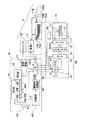
図1は、本発明を適用したインクジェット記録装置の全体構成を示すブロック図である。
【0018】
図1に示すように、本形態のインクジェット記録装置1では、コンピュータ90に対してはスキャナ120と、カラーのインクジェットプリンタ100とが接続され、このコンピュータ90に所定のプログラムがロードされ、実行されることにより、インクジェット記録装置1は全体として記録装置として機能する。
【0019】
このコンピュータ90は、プログロムに従って画像処理に関わる動作を制御するための各種演算処理を実行するCPU81を中心に、バス80により相互に接続された次の各部を備える。ROM82は、CPU81で各種演算処理を実行するのに必要なプログラムやデータを予め格納しており、RAM83は、同じくCPU81で各種演算処理を実行するのに必要な各種プログラムやデータが一時的に読み書きされるメモリである。入力インターフェース84は、スキャナ120やキーボード140からの信号の入力を司り、出力インターフェース85は、インクジェットプリンタ100へのデータの出力を司る。CRTC86は、カラー表示可能なCRT210への信号出力を制御し、ディスクコントローラ(DDC)87は、ハードディスク160やフレキシブルドライブ150あるいは図示しないCD−ROMドライブとの間のデータの授受を制御する。ハードディスク160には、RAM83にロードされて実行される各種プログラム、デバイスドライバの形式で提供される各種プログラム、およびディスクドライバの形式で提供される各種プログラムなどが記憶されている。
【0020】
この他、バス80にはシリアル入力インターフェース(SIO)88が接続されている。このSIO88は、モデム180に接続されており、モデム180を介して、公衆電話回線PNTに接続されている。コンピュータ90は、このSIO88およびモデム180を介して、外部のネットワークに接続されており、特定のサーバSVに接続することにより、画像処理に必要なプログラムをハードディスクにダウンロードすることも可能である。また、必要なプログラムをフレキシブルディスクFDやCD−ROMによりダウンロードし、コンピュータ90に実行させることも可能である。
【0021】
図2は、本形態のインクジェット記録装置のソフトウエアの構成を示すブロック図である。
【0022】
コンピュータ90では、所定のオペレーティングシステムの下でアプリケーションプログラム95が動作している。オペレーティングシステムには、ビデオドライバ91やプリンタドライバ96が組み込まれており、アプリケーションプログラム95からはこれらのドライバ91、96を介して、インクジェットプリンタ100に転送するための中間画像データが出力される。画像のレタッチなどを行うアプリケーションプログラム95は、スキャナ12から画像を読み込み、これに対して所定の処理を行いつつビデオドライバ91を介してCRTディスプレイ21に画像を表示している。スキャナ12から供給されるデータORGは、カラー原稿から読み取られ、赤(R)、緑(G)、青(B)の3色の色成分からなる原カラー画像データである。
【0023】
このアプリケーションプログラム95が記録命令を発すると、コンピュータ90のプリンタドライバ96が画像情報をアプリケーションプログラム95から受け取り、これをプリンタドライバ96が、インクジェットプリンタ100で処理可能な信号(ここではシアン、マゼンダ、イエロー、ブラックの各色について多値化された信号)に変換する。ここに示す例では、プリンタドライバ96の内部には、解像度変換モジュール97と、色補正モジュール98と、色補正テーブルLUTと、ハーフトーンモジュール99と、ラスタライザ94とが備えられている。
【0024】
解像度変換モジュール97は、アプリケーションプログラム95が扱っているカラー画像データの解像度、すなわち、単位長さ当たりの画素数をプリンタドライバ96が扱うことのできる解像度に変換する役割を果たす。こうして解像度変換された画像データは、まだRGBの3色からなる画像情報であるから、色補正モジュール98は色補正テーブルLUTを参照しつつ、各画素毎にインクジェットプリンタ100が使用するシアン(C)、マゼンダ(M)、イエロー(Y)、黒(BK)の各色のデータに変換する。こうして色補正されたデータは、たとえば、256階調等の幅で階調値を有している。ハーフトーンモジュール99は、ドットを分散して形成することにより、インクジェットプリンタ100で所定の階調値を表現するためのハーフトーン処理を実行する。このようにして処理された画像データは、ラスタライザ94によりインクジェットプリンタ100に転送すべきデータ順に並び換えられて、最終的な画像データFNL(記録情報)として出力される。本例では、インクジェットプリンタ100は画像データFNLに従ってドットを形成する役割を果たすのみであり、画像処理は行っていない。また、コンピュータ90の側のプリンタドライバ96では、インクジェットプリンタ100の内部の駆動信号の調整などを行っていないが、駆動信号に含まれる複数のパルス信号の設定などを、インクジェットプリンタ100との双方向通信の機能を利用してプリンタドライバ96の側で行うことも可能である。
【0025】
(インクジェットプリンタの全体構成)
図3は、インクジェットプリンタの要部を示す斜視図である。
【0026】
図3に示すように、インクジェットプリンタ100では、キャリッジ101がタイミングベルト102を介してキャリッジ機構12のキャリッジモータ103に接続され、ガイド部材104に案内されて記録用紙105の紙幅方向に往復動するように構成されている。インクジェットプリンタ100には、紙送りローラ106を用いた紙送り機構11が形成されている。キャリッジ101には記録用紙105と対向する面、この図に示す例では下面にインクジェット式の記録ヘッド10が取り付けられている。記録ヘッド10は、キャリッジ101の上部に載置されているインクカートリッジ107からインクの補給を受けてキャリッジ101の移動に合わせて記録用紙105にインク滴を吐出してドットを形成し、記録用紙105に画像や文字を記録する。インクカートリッジ107としては、黒(BK)のインクカートリッジ、およびシアン(C)、マゼンダ(M)、イエロー(Y)のカラーインクカートリッジが搭載されているが、これらのカートリッジのうちの一つのみを図示してある。
【0027】
ここで、図3には単票の記録紙が図示されているが、本形態のインクジェットプリンタ100には、単票の記録用紙、およびロール紙(連続紙)のいずれをも使用することができるように、各々の記録紙が供給される供給口(図示せず)が形成されている。
【0028】
なお、インクジェットプリンタ100の非記録領域には、キャッピング装置108が構成され、記録の休止中に記録ヘッド10のノズル開口を封止する。従って、記録の休止中、インクから溶媒が飛散することによってインクが増粘あるいはインク膜を形成することを抑制することができるので、記録の休止中にノズルに目詰まりが発生するのを防止できる。また、キャッピング装置108は、記録動作中に行われるフラッシング動作による記録ヘッド10からのインク滴を受ける。キャッピング装置108の近傍にはワイピング装置109が配置され、このワイピング装置109は、記録ヘッド10の表面をブレードなどでワイピングすることにより、そこに付着したインク滓や紙粉を拭き取るように構成されている。
【0029】
(プリンタの制御系の構成)
図4は、本形態のインクジェットプリンタ100の機能ブロック図である。
【0030】
図4において、インクジェットプリンタ100は、プリントコントローラ40とプリントエンジン5とから構成されている。プリントコントローラ40は、コンピュータ90(図1、2参照。)からの多値階調情報を含む画像データFNL(記録情報)などを受信するインターフェース43と、多値階調情報を含む記録情報などの各種データの記憶を行うDRAMからなる受信バッファ44A、中間バッファ44B、並びにSRAMからなる出力バッファ44Cと、各種データ処理を行うためのルーチンなどを記憶したROM45と、CPUなどからなる制御部46と、発振回路47と、記録ヘッド10への駆動信号COMを発生させる駆動信号生成回路48と、ドットパターンデータに展開された記録データSIおよび駆動信号COMなどをプリントエンジン5に送信するためのインターフェース49とを備えている。
【0031】
(記録ヘッド10の構成)
プリントエンジン5は、記録ヘッド10と、紙送り機構11と、キャリッジ機構12とを備えている。紙送り機構11は、単票供給口11Aから供給されるA4などの単票の記録用紙105A、あるいは連続紙供給口11Bから供給されるロール紙などの連続紙105Bなどを順次送り出して副走査を行うものであり、キャリッジ機構12は、記録ヘッド10を主走査させるものである。
【0032】
記録ヘッド10は、所定のタイミングで各ノズル開口111からインク滴を吐出させるものである。記録ヘッド10には、シフトレジスタ13、ラッチ回路14、レベルシフタ15、およびスイッチ回路16を備えるヘッド駆動回路50が構成されている。このヘッド駆動回路50において、プリントコントローラ40においてドットパターンデータに展開された記録データSIは、発振回路47からのクロック信号CLKに同期してインターフェース49を介して記録ヘッド10のヘッド駆動回路50に転送される。このヘッド駆動回路50において、記録データが全ノズル分、シフトレジスタ13の各素子にセットされたならば、制御部46は、所定のタイミングでラッチ回路14へラッチ信号(LAT)を出力する。このラッチ信号により、ラッチ回路14はシフトレジスタ13にセットされたノズル選択データをラッチする。このラッチ回路14がラッチしたノズル選択データは、電圧変換器であるレベルシフタ15に印加される。このレベルシフタ15は、記録データSIが例えば「1」の場合に、スイッチ回路16が駆動可能な電圧値、例えば、数十ボルトに変換する。そして、この変換された記録データSIはスイッチ回路16の各スイッチング素子に印加され、各素子は接続状態になる。
【0033】
ここで、スイッチ回路16の各スイッチング素子には、駆動信号生成回路48が生成した駆動信号COMが印加されており、スイッチ回路16の各スイッチング素子が接続状態になると、この素子に接続された圧力発生素子17に駆動信号COMが印加される。従って、記録ヘッド10では、記録データSIに対応するノズル選択データによって圧力発生素子17に駆動信号COMを印加するか否かを制御することができる。
【0034】
例えば、ノズル選択データ(記録データSI)が「1」の期間においては、スイッチ回路16の素子が接続状態となるので、駆動信号COMを圧力発生素子17に供給することができ、この供給された駆動信号COMにより圧力発生素子17が変位(変形)する。また、記録データSIが「0」に期間においてはスイッチ回路16の素子が非接続状態になるので、圧力発生素子17への駆動信号COMの供給は遮断される。なお、このノズル選択データ(記録データSI)が「0」の期間において、各圧力発生素子17は直前の電荷を保持するので、直前の変位状態が維持される。
【0035】
このように、スイッチ回路16の素子がオン状態になって駆動信号COMが圧力発生素子17に印加されると、ノズル開口111に連通する圧力発生室113が収縮し、圧力発生室113内のインクが加圧されたとき、圧力発生室113内のインクはインク滴としてノズル開口111から吐出され、記録用紙などの上にドットを形成する。
【0036】
(駆動信号生成回路48の構成)
図5は、駆動信号生成回路48の構成を示すブロック図である。図6は、駆動信号生成回路48において駆動信号COMに含まれる各駆動パルスを生成していく過程を示す説明図である。図7は、駆動信号生成回路48においてデータ信号を用いてメモリに電位差(ΔV)を設定する場合の各信号のタイミングを示すタイミングチャートである。
【0037】
図5において、駆動信号生成回路48には、制御部46からの信号を受け取って記録するメモリ81、このメモリ81の内容を読み出して一時的に保持する第1のラッチ82、この第1のラッチ82の出力と後述するもう一つの第2のラッチ84の出力とを加算する加算器83、第2のラッチ84の出力をアナログデータに変換するA/D変換器86、変換されたアナログ信号を駆動信号の電圧まで増幅する電圧増幅部88、およびこの電圧増幅部88から出力される駆動信号に対する電流増幅器89から構成されている。ここで、メモリ81は、駆動信号COMの波形を決める所定のパラメータを記憶しておく波形データ記憶部である。駆動信号COMの波形は、予め制御部46から受け取った所定のパラメータにより決定される。すなわち、駆動信号生成回路48は、クロック信号801、802、803、データ信号830、アドレス信号810、811、812、813、リセット信号820およびイネーブル信号840を受け取る。
【0038】
このように構成した駆動信号生成回路48においては、図6に示すように、駆動信号COMの生成に先立って、制御部46の電圧変化量を示すいくつかのデータ信号と、そのデータ信号のアドレスとがクロック信号801に同期して、駆動信号生成回路48のメモリ81に出力される。データ信号830は、図7に示すように、クロック信号801を同期信号とするシリアル転送により、データをやり取りする構成になっている。すなわち、制御部46から所定の電圧変化量を転送する場合には、まず、クロック信号801に同期して複数ビットのデータ信号を出力し、その後、このデータを格納するアドレスをイネーブル信号840に同期してアドレス信号810〜813として出力する。メモリ81は、このイネーブル信号840が出力されたタイミングでアドレス信号を読み取り、受け取ったデータをそのアドレスに書き込む。アドレス信号810〜813は4ビットの信号なので、最大16種類の電圧変化量をメモリ81に記憶することができる。なお、データの最上位のビットは符号として用いられている。
【0039】
各アドレスA、B、・・・への電圧変化量の設定が終了した後、アドレスBがアドレス信号810〜813に出力されると、最初のクロック信号802により、このアドレスBに対応した電圧変化量が第1のラッチ回路82により保持される。この状態で、次にクロック信号803が出力されると、第2のラッチ回路84の出力に第1のラッチ回路82の出力が加算された値が、第2のラッチ回路84に保持される。すなわち、図6に示すように、一旦、アドレス信号に対応した電圧変化量が選択されると、その後、クロック信号803を受けるたびに、第2のラッチ回路84の出力は、その電圧変化量に従って増減する。メモリ81のアドレスBに格納された電圧変化量ΔV1とクロック信号803の単位時間ΔTにより駆動波形のスルーレートが決まる。なお、増加か減少かは、各アドレスに格納されたデータの符号により決定される。
【0040】
図6に示した例では、アドレスAには、電圧変化量として値0、すなわち、電圧を維持する場合の値が格納されている。従って、クロック信号802によりアドレスAが有効となると、駆動信号の波形は、増減のないフラットな状態に保たれる。また、アドレスCには、駆動波形のスルーレートを決定するために、単位時間ΔT当たりの電圧変化量ΔV2が格納されている。従って、クロック信号802によりアドレスCが有効になった後は、この電圧ΔV2ずつ電圧が低下していくことになる。
【0041】
このように制御部46からアドレス信号とクロック信号とを出力するだけで、駆動信号COMの波形を自由に制御でき、その一例が図8に表わされている。
【0042】
図8に示す駆動波形COMにおいては、その電圧値が中間電位Vmからスタートした後(ホールドパルス311)、時刻T1から時刻T2までの間に最大電位VPSまで一定の傾きで上昇し(充電パルス312)、時刻T2から時刻T3まで最大電位VPSを維持する(ホールドパルス313)。次に、時刻T3から時刻T4までの間に最低電位VLSまで一定の傾きで下降した後(放電パルス314)、時刻T4から時刻T5まで最低電位VLSを維持する(ホールドパルス315)。そして、時刻T5から時刻T6までに電圧値は中間電位Vmまで一定の傾きで上昇する(充電パルス316)。
【0043】
従って、図4に示す圧力発生素子17に充電パルス312が印加されると、圧力発生素子17は圧力発生室113の容積を膨張させる方に撓み、圧力発生室113に負圧を発生させる。その結果、メニスカスはノズル開口111から引っ込み、次に、放電パルス314を印加すると、圧力発生素子17は圧力発生室113の容積を収縮させるように撓み、圧力発生室113に正圧が発生する。その結果、ノズル開口111からインク滴が吐出される。そして、ホールドパルス315が印加された後、充電パルス316を印加してメニスカスの振動を抑える。
【0044】
(温度補正の内容)
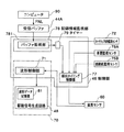
図9は、図1に示すインクジェット記録装置において、インク滴の吐出条件に温度補正を施すための構成を示すブロック図である。
【0045】
インクジェット記録装置1では、インク滴の吐出を繰り返し行なっていくうちに記録ヘッド10が温度上昇を起こすと、インクの粘度が変化する結果、インク吐出量が変動し、記録の品位が低下する。そこで、記録ヘッド10には、図4および図9に示すように、この記録ヘッド10の温度を一定時間毎に検出する温度センサ60が構成され、この温度センサ60の検出結果は、制御部46の温度補正部70に入力されるようになっている。
【0046】
この温度補正部70では、温度センサ60によって検出された記録ヘッド10の温度に基づいて駆動波形COMの波形や電圧値を変更するように、制御部46には、駆動信号生成回路48を制御する波形制御部71が制御部46の機能の一部として構成され、記録ヘッド10の温度が高くなったときにはインクの粘度が低いので、波形制御部71は、駆動信号生成部48に対して、記録ヘッド10の温度(インクの温度)が上昇しても一定量のインク滴を吐出するように、図8に示す駆動信号COMの振幅を狭めるなどの補正を行なってインク滴の目標重量を少なめに設定する。
【0047】
また、温度補正部70では、以下に説明するように、記録ヘッド10の温度が低くなったときにはインクの粘度が高いので、波形制御部71は、駆動信号生成部48に対して、記録ヘッド10の温度(インクの温度)が低下しても一定量のインク滴を吐出するように、図8に示す駆動信号COMの振幅を広げるなどの補正を行なってインク滴の目標重量を多めに設定する。
【0048】
このような温度低下も考慮した温度補正を適正なタイミングで行えるように、本形態のインクジェット記録装置1では、図4および図9に示すように、単票供給口11Aには、単票105Aがあるか否かを監視する単票検出センサ75A(媒体切れ監視手段/中断監視手段・記録停止監視手段)が配置され、連続紙供給口11Bには、連続紙105Bがあるか否かを監視する連続紙検出センサ75B(媒体切れ監視手段/中断監視手段・記録停止監視手段)が配置されている。これらのセンサ75A、75Bの検出結果は、制御部46の検出タイミング制御部77に入力されている。
【0049】
ここで、検出タイミング制御部77は、温度センサ60に対して記録ヘッド10の温度を検出するタイミングを制御するものであり、単票検出センサ75Aあるいは連続紙検出センサ75Bの監視結果に基づいて、単票紙105Aおよび連続紙105Bのうち、これまで使用していた記録紙に紙切れが発生したときには、その間、インク滴の吐出が中断され、記録ヘッド10の温度(インクの温度)が低下している可能性があるとして、温度センサ60に対して記録ヘッド10の温度を検出させる。従って、温度補正部70では、温度センサ60の監視結果に基づいて、記録ヘッド10の温度が低くなったときには、波形制御部71が、駆動信号生成部48に対して、図8に示す駆動信号COMの振幅を広げるなどの補正を行なってインク滴の目標重量を多めに設定する。
【0050】
また、本形態では、図9に示すように、制御部46には、インク滴の吐出の中断を監視する手段(中断監視手段・記録停止監視手段)として記録情報監視部78とタイマー79とが構成されている。記録情報監視部78では、図1および図2を参照して説明したコンピュータ90からインクジェットプリンタ100に画像データFNLが入力されているか否かを監視し、画像データFNLの入力が中断すると、中断してからの経過時間をタイマー79が計測する。従って、検出タイミング制御部77は、タイマー79の計時結果において、画像データFNLの入力が中断してから所定の時間が経過したときには、インク滴の吐出が所定時間、中断したため、記録ヘッド10の温度(インクの温度)が低下している可能性があるとして、温度センサ60に対して記録ヘッド10の温度を検出させる。従って、温度補正部70では、温度センサ60の監視結果に基づいて、記録ヘッド10の温度が低くなったときには、波形制御部71が、駆動信号生成部48に対して、図8に示す駆動信号COMの振幅を広げるなどの補正を行なってインク滴の目標重量を多めに設定する。
【0051】
このようにして記録情報監視部78で記録動作を停止しているか否かを監視するにあたって、本形態では、記録情報監視部78には、受信バッファ44Aに受信データがあるか否かを監視するバッファ監視部781が形成されている。すなわち、コンピュータ90からの記録情報FNLは、まず、受信バッファ44Aに入力されるので、この受信バッファ44Aにデータがない限り、記録動作が行われない。それ故、バッファ監視部781が受信バッファ44Aに受信データがあれば、記録動作中であることを判別でき、受信バッファ44Aに受信データがなければ記録動作が停止中であることを判別できる。
【0052】
さらに、本形態では、インクカートリッジ107の装着状態を監視するカートリッジ有無監視センサ72(カートリッジ107の交換監視手段/中断監視手段・記録停止監視手段)が構成され、このカートリッジ有無監視センサ72の検出結果は、制御部46の検出タイミング制御部77に入力されている。従って、検出タイミング制御部77は、カートリッジ有無監視センサ72の監視結果に基づいて、カートリッジ107が外されたときには、インク滴の吐出が所定時間、中断して、記録ヘッド10の温度(インクの温度)が低下している可能性があるとして、温度センサ60に対して記録ヘッド10の温度を検出させる。従って、温度補正部70では、温度センサ60の監視結果に基づいて、記録ヘッド10の温度が低くなったときには、波形制御部71が、駆動信号生成部48に対して、図8に示す駆動信号COMの振幅を広げるなどの補正を行なってインク滴の目標重量を多めに設定する。
【0053】
このように、本形態のインクジェット記録装置1では、インク滴の吐出を中断すると、記録ヘッド10の温度が低下し、インクの粘度が上昇していくので、それまでと同一の条件でインク滴を吐出すると、インク滴の重量が少なすぎることになることに着目して、インク滴の吐出動作が中断されたことを監視し、この監視結果に基づいて、インク滴の吐出動作が中断されたときに、記録ヘッドの温度検出を行う。従って、本形態のインクジェット記録装置1によれば、インク滴の吐出を中断したときに記録ヘッド10の温度を検出して温度補正を行うため、インク滴の吐出の中断により記録ヘッド10の温度が低下してインクの粘度が上昇したときでも、このような粘度の変化を吸収するように、インク滴の吐出条件を補正するので、インク滴の重量が変動しない。それ故、品位の高い記録を行うことができる。また、本形態では、インク滴の吐出を停止している間に温度補正を行なうので、記録のスループットが低下しないという利点がある。
【0054】
[その他の実施の形態]
図10は、本発明を適用した別のインクジェット記録装置において、インク滴の吐出条件に温度補正を施すための構成を示すブロック図である。
【0055】
図10に示すインクジェット記録装置において、記録情報監視部78には、さらに、バッファ監視部781の監視結果に基づいて、所定の期間、受信バッファ44Aに受信データがない状態から、コンピュータから記録情報FNLが入力されることにより受信データがある状態になったときには、これから記録を開始するものと判断してその旨の信号を検出タイミング制御部77に出力する記録開始監視部782(記録開始監視手段)が構成されている。
【0056】
このため、これまで記録動作を停止、あるいは中断していた状態から記録動作を開始する直前には、必ず、検出タイミング制御部77が温度センサ60に対して記録ヘッド10の温度を検出させる。従って、温度補正部70では、温度センサ60の監視結果に基づいて、記録ヘッド10の記録開始直前の温度に応じて、波形制御部71が、駆動信号生成部48に対して、図8に示す駆動信号COMの振幅を広げる補正、あるいは駆動信号COMの振幅を狭める補正を行なう。それ故、本形態のインクジェット記録装置1では、記録動作を停止、あるいは中断していても、インク滴を吐出する直前の記録ヘッド10の温度に対応する正確な温度補正を行なうことができるので、所定重量のインク滴を最初から安定して吐出することができる。
【0057】
また、上記形態では、圧力発生素子として圧電振動子を用いたインクジェット記録装置を例に説明したが、本発明は、熱により圧力発生室内に圧力を発生させるインクジェット記録装置などにも適用できる。
【0058】
【発明の効果】
以上説明したように、本発明に係るインクジェット記録装置では、インク滴の吐出を停止すると、記録ヘッドの温度が低下し、インクの粘度が上昇していくので、それまでと同一の条件でインク滴を吐出すると、インク滴の重量が少なすぎることになることに着目して、インク滴の吐出動作が停止していることを監視する記録停止監視手段を設け、この記録停止監視手段の監視結果に基づいて、インク滴の吐出動作が停止されたときに、検出タイミング制御手段は、温度検出手段に対して記録ヘッドの温度検出を行わせる。従って、本発明によれば、インク滴の吐出を停止したときに記録ヘッドの温度を検出して温度補正を行うため、インク滴の吐出の中断により記録ヘッドの温度が低下してインクの粘度が上昇したときでも、このような粘度の変化を吸収するように、インク滴の吐出条件を補正するので、インク滴の重量が変動しない。それ故、品位の高い記録を行うことができる。
【0059】
【図面の簡単な説明】
【図1】本発明を適用したインクジェット記録装置の全体構成を示すブロック図である。
【図2】図1に示すインクジェット記録装置のソフトウエアの構成を示すブロック図である。
【図3】図1に示すインクジェット記録装置に用いたインクジェットプリンタの要部を示す斜視図である。
【図4】図3に示すインクジェットプリンタの機能ブロック図である。
【図5】図1に示すインクジェット記録装置に形成されている駆動信号生成回路のブロック図である。
【図6】図5に示す駆動信号生成回路において駆動信号に含まれる各パルスを生成していく過程を示す説明図である。
【図7】図5に示す駆動信号生成回路においてデータ信号に基づいてメモリにスルーレートを設定する場合の各信号のタイミングを示すタイミングチャートである。
【図8】図1に示すインクジェット記録装置に用いた駆動信号の一例を示す波形図である。
【図9】図1に示すインクジェット記録装置において、インク滴の吐出条件に温度補正を施すための構成を示すブロック図である。
【図10】本発明を適用した別のインクジェット記録装置において、インク滴の吐出条件に温度補正を施すための構成を示すブロック図である。
【符号の説明】
1 インクジェット記録装置
5 プリントエンジン
10 記録ヘッド
11A 単票供給口
11B 連続紙供給口
13 シフトレジスタ
14 ラッチ回路
15 レベルシフタ
16 スイッチ回路
17 圧力発生素子
44A 受信バッファ
46 制御部
48 駆動波形生成回路
50 ヘッド駆動回路
60 温度センサ
70 温度補正部
71 波形制御部
72 カートリッジ有無監視センサ(交換有無監視手段/中断監視手段)
75A 単票検出センサ(媒体切れ監視手段/中断監視手段)
75B 連続紙検出センサ(媒体切れ監視手段/中断監視手段)
77 検出タイミング制御部(検出タイミング制御手段)
78 記録情報監視部(中断監視手段)
79 タイマー(計時手段/中断監視手段)
105A 単票の記録用紙
105B 連続紙
781 バッファ監視部
782 記録開始監視部
COM 駆動信号
FNL 画像データ(記録情報)[0001]
BACKGROUND OF THE INVENTION
The present invention relates to an ink jet recording apparatus used as an ink jet printer or an ink jet plotter. More specifically, the present invention relates to a temperature correction technique in an ink jet recording apparatus.
[0002]
[Prior art]
In a recording head of an ink jet recording apparatus used as an ink jet printer, an ink jet plotter, or the like, a pressure generating chamber in which pressure generating elements such as a plurality of piezoelectric vibrators (for example, piezoelectric elements) corresponding to the plurality of nozzle openings communicate with the nozzle openings Ink droplets are ejected from the nozzle openings by pressurizing the ink.
[0003]
In such an ink jet recording apparatus, when the temperature of the recording head rises while ink is repeatedly ejected, the viscosity of the ink changes, resulting in fluctuations in the ink ejection amount and degradation in recording quality. Therefore, measures such as detecting the temperature of the recording head and changing the drive waveform and drive voltage based on the temperature detection result are considered.
[0004]
[Problems to be solved by the invention]
However, the conventional temperature correction method of the ink jet recording apparatus that is considered is not necessary because the actual recording operation and the temperature detection timing are not linked, such as detecting the temperature of the recording head at regular intervals. However, there is a problem that temperature correction is not performed. For example, the temperature change of the recording head includes not only a temperature increase but also a temperature decrease when the ejection of ink droplets is interrupted. The temperature correction method has a problem that the temperature cannot be corrected at an appropriate timing.
[0005]
SUMMARY OF THE INVENTION An object of the present invention is to provide an ink jet recording apparatus capable of detecting the temperature of a recording head at a timing in accordance with an actual recording operation, and performing temperature correction on the recording conditions based on the detection result. is there.
[0006]
[Means for Solving the Problems]
According to one aspect of the present invention, a plurality of pressure generating elements corresponding to each of the plurality of nozzle openings pressurize ink in a pressure generating chamber that communicates with the nozzle openings, whereby ink droplets are applied from the nozzle openings to the recording medium. A recording head for discharging the ink, a temperature detecting means for detecting the temperature of the recording head, a detection timing control means for causing the temperature detecting means to detect the temperature of the recording head at a predetermined timing, and the recording head. A driving signal generating means for generating a driving signal for driving; a buffer for temporarily storing halftone processed recording information used by the driving signal generating means to generate the driving signal; The temperature correction method adjusts the drive waveform of the drive signal based on the temperature detection result by the temperature detection means so that the ink discharge amount becomes constant. Recording stop monitoring means for monitoring whether or not ejection of ink droplets is stopped, and medium outage monitoring means for monitoring whether or not the recording medium to be recorded no longer exists, The detection timing control means detects that the ejection of ink droplets is stopped by the recording stop monitoring means, detects the absence of the recording medium by the medium shortage monitoring means, and has not recorded in the buffer. When the recording information is stored, an ink jet recording apparatus is used in which the temperature detecting unit detects the temperature of the recording head before ink droplet ejection is started. The
[0007]
In an ink jet recording apparatus, if the temperature of the recording head rises as ink droplets are repeatedly ejected, the viscosity of the ink decreases, so if ink droplets are ejected under the same conditions as before, the weight of the ink droplets will increase. It will be too much. Therefore, in the ink jet recording apparatus, the temperature of the recording head is monitored, and temperature correction is performed on the ink droplet ejection conditions based on the monitoring result. In addition, when the ink droplet ejection is stopped, the temperature of the recording head decreases and the viscosity of the ink increases. Therefore, if the ink droplet is ejected under the same conditions as before, the weight of the ink droplet is too small. Become.
[0008]
Focusing on this point, the present invention provides a recording stop monitoring means for monitoring that the ink droplet ejection operation has been stopped, and the ink droplet ejection operation is stopped based on the monitoring result of the recording stop monitoring means. When this is done, the detection timing control means causes the temperature detection means to detect the temperature of the recording head. Therefore, according to the present invention, when the ejection of the ink droplets is stopped, the temperature of the recording head is detected and temperature correction is performed. Even when it rises, the ink droplet ejection conditions are corrected at an appropriate timing so as to absorb such a change in viscosity, so that the weight of the ink droplet does not fluctuate. Therefore, high quality recording can be performed. Further, since the temperature correction is performed during the period in which the ejection of ink droplets is stopped, it is not necessary to interrupt the recording operation for the temperature correction, so that the recording throughput is high.
[0009]
In the present invention, the recording stop monitoring means is, for example, interruption monitoring means for monitoring that the ink droplet ejection operation has been temporarily interrupted.
[0010]
In the present invention, the interruption monitoring unit includes, for example, a time measuring unit that measures an elapsed time after the ejection of the ink droplet is stopped, and the detection timing control unit is configured to measure the ink based on the time measurement result of the time measuring unit. When the ejection of the droplet is interrupted for a predetermined time or longer, the temperature detection unit is caused to detect the temperature of the recording head.
[0011]
Here, the time counting means, for example, determines the elapsed time since the stop of the input of the recording information, assuming that the discharge of the ink droplet is stopped when the input of the recording information for specifying whether or not the ink droplet is discharged is stopped. measure.
[0012]
In the present invention, the interruption monitoring unit may include a replacement monitoring unit that monitors whether the ink container that supplies ink to the pressure generating chamber has been replaced. In this case, the detection timing control unit detects the temperature of the recording head with respect to the temperature detection unit when the ink container is replaced based on the monitoring result of the replacement monitoring unit. Make it.
[0013]
In the present invention, the interruption monitoring means may include medium shortage monitoring means for monitoring that the recording medium is interrupted. In this case, the detection timing control means causes the temperature detection means to detect the temperature of the recording head when the recording medium is interrupted based on the monitoring result of the medium outage monitoring means.
[0014]
In the present invention, the interruption monitoring means includes, for example, buffer monitoring means for monitoring whether or not there is data in a buffer for processing recording information, and data is stored in the buffer based on a monitoring result of the buffer monitoring means. When there is no ink droplet, it is detected that the ejection of the ink droplet is stopped.
[0015]
In the present invention, the recording stop monitoring unit may include a recording start monitoring unit that monitors the timing of starting the ink droplet ejection operation. In this case, the detection timing control unit includes at least the recording stop monitoring unit. Based on the monitoring result of the means and the monitoring result of the recording start monitoring means, the temperature detecting means is caused to detect the temperature of the recording head immediately before the ink droplet ejection operation is started. That is, immediately before starting the recording operation from the state where the recording operation has been stopped or interrupted so far, the detection timing control means always causes the temperature detection means to detect the temperature of the recording head, and the temperature correction means Based on the monitoring result of the temperature detection means at that time, temperature correction is performed such as increasing the amplitude of the drive signal or decreasing the amplitude of the drive signal in accordance with the temperature immediately before the start of recording of the recording head. Accordingly, even when the recording operation is stopped or interrupted, it is possible to perform accurate temperature correction corresponding to the temperature of the recording head immediately before ejecting the ink droplets. It can be discharged.
[0016]
DETAILED DESCRIPTION OF THE INVENTION
An inkjet recording apparatus to which the present invention is applied will be described with reference to the drawings.
[0017]
(Overall configuration of inkjet recording apparatus)
FIG. 1 is a block diagram showing the overall configuration of an ink jet recording apparatus to which the present invention is applied.
[0018]
As shown in FIG. 1, in the
[0019]
The
[0020]
In addition, a serial input interface (SIO) 88 is connected to the
[0021]
FIG. 2 is a block diagram showing a software configuration of the ink jet recording apparatus according to the present embodiment.
[0022]
In the
[0023]
When the
[0024]
The
[0025]
(Overall configuration of inkjet printer)
FIG. 3 is a perspective view showing a main part of the ink jet printer.
[0026]
As shown in FIG. 3, in the
[0027]
Here, FIG. 3 shows a single sheet of recording paper, but the
[0028]
Note that a
[0029]
(Configuration of printer control system)
FIG. 4 is a functional block diagram of the
[0030]
In FIG. 4, the
[0031]
(Configuration of the recording head 10)
The
[0032]
The
[0033]
Here, the drive signal COM generated by the drive
[0034]
For example, during the period in which the nozzle selection data (recording data SI) is “1”, the elements of the
[0035]
Thus, when the element of the
[0036]
(Configuration of Drive Signal Generation Circuit 48)
FIG. 5 is a block diagram showing a configuration of the drive
[0037]
In FIG. 5, the drive
[0038]
In the drive
[0039]
After the setting of the voltage change amount to each address A, B,... Is completed, when the address B is output to the address signals 810 to 813, the voltage change corresponding to this address B is made by the first clock signal 802. The quantity is held by the
[0040]
In the example illustrated in FIG. 6, the address A stores a value 0 as a voltage change amount, that is, a value when the voltage is maintained. Therefore, when the address A is validated by the clock signal 802, the waveform of the drive signal is kept flat without any increase or decrease. The address C stores a voltage change amount ΔV2 per unit time ΔT in order to determine the slew rate of the drive waveform. Therefore, after the address C is validated by the clock signal 802, the voltage decreases by this voltage ΔV2.
[0041]
In this way, the waveform of the drive signal COM can be freely controlled simply by outputting the address signal and the clock signal from the
[0042]
In the drive waveform COM shown in FIG. 8, after the voltage value starts from the intermediate potential Vm (hold pulse 311), it rises at a constant slope to the maximum potential VPS from time T1 to time T2 (charge pulse 312). ), The maximum potential VPS is maintained from time T2 to time T3 (hold pulse 313). Next, after falling from the time T3 to the time T4 with a constant slope to the lowest potential VLS (discharge pulse 314), the lowest potential VLS is maintained from the time T4 to time T5 (hold pulse 315). Then, from time T5 to time T6, the voltage value rises at a constant slope to the intermediate potential Vm (charging pulse 316).
[0043]
Therefore, when the charging
[0044]
(Content of temperature correction)
FIG. 9 is a block diagram showing a configuration for performing temperature correction on ink droplet ejection conditions in the ink jet recording apparatus shown in FIG.
[0045]
In the ink
[0046]
In the
[0047]
Further, in the
[0048]
In the
[0049]
Here, the detection
[0050]
In this embodiment, as shown in FIG. 9, the
[0051]
In this manner, when the recording information monitoring unit 78 monitors whether or not the recording operation is stopped, in this embodiment, the recording information monitoring unit 78 monitors whether there is reception data in the
[0052]
Further, in this embodiment, a cartridge presence / absence monitoring sensor 72 (replacement monitoring means / interruption monitoring means / recording stop monitoring means for the cartridge 107) for monitoring the mounting state of the
[0053]
As described above, in the ink
[0054]
[Other embodiments]
FIG. 10 is a block diagram showing a configuration for performing temperature correction on ink droplet ejection conditions in another ink jet recording apparatus to which the present invention is applied.
[0055]
In the ink jet recording apparatus shown in FIG. 10, the recording information monitoring unit 78 further receives the recording information FNL from the computer from the state in which there is no reception data in the
[0056]
Therefore, the detection
[0057]
In the above embodiment, the ink jet recording apparatus using a piezoelectric vibrator as a pressure generating element has been described as an example. However, the present invention can also be applied to an ink jet recording apparatus that generates pressure in a pressure generating chamber by heat.
[0058]
【The invention's effect】
As described above, in the ink jet recording apparatus according to the present invention, when the ink droplet ejection is stopped, the temperature of the recording head decreases and the viscosity of the ink increases. Focusing on the fact that the weight of the ink droplet is too small when the ink is ejected, a recording stop monitoring means for monitoring that the ink droplet ejection operation is stopped is provided. Based on this, when the ink droplet ejection operation is stopped, the detection timing control means causes the temperature detection means to detect the temperature of the recording head. Therefore, according to the present invention, the temperature of the recording head is detected and the temperature of the recording head is corrected when the ejection of the ink droplet is stopped. Even when it rises, the ink droplet ejection conditions are corrected so as to absorb such a change in viscosity, so that the weight of the ink droplet does not fluctuate. Therefore, high quality recording can be performed.
[0059]
[Brief description of the drawings]
FIG. 1 is a block diagram showing an overall configuration of an ink jet recording apparatus to which the present invention is applied.
FIG. 2 is a block diagram showing a software configuration of the ink jet recording apparatus shown in FIG.
3 is a perspective view showing a main part of an ink jet printer used in the ink jet recording apparatus shown in FIG. 1. FIG.
4 is a functional block diagram of the ink jet printer shown in FIG. 3. FIG.
5 is a block diagram of a drive signal generation circuit formed in the ink jet recording apparatus shown in FIG.
6 is an explanatory diagram showing a process of generating each pulse included in the drive signal in the drive signal generation circuit shown in FIG. 5;
7 is a timing chart showing the timing of each signal when a slew rate is set in a memory based on a data signal in the drive signal generation circuit shown in FIG. 5;
8 is a waveform diagram showing an example of a drive signal used in the ink jet recording apparatus shown in FIG.
9 is a block diagram showing a configuration for performing temperature correction on ink droplet ejection conditions in the ink jet recording apparatus shown in FIG. 1. FIG.
FIG. 10 is a block diagram showing a configuration for performing temperature correction on ink droplet ejection conditions in another ink jet recording apparatus to which the present invention is applied.
[Explanation of symbols]
1 Inkjet recording device
5 Print engine
10 Recording head
11A single slot supply port
11B Continuous paper supply port
13 Shift register
14 Latch circuit
15 level shifter
16 Switch circuit
17 Pressure generating element
44A Receive buffer
46 Control unit
48 Drive waveform generation circuit
50 Head drive circuit
60 Temperature sensor
70 Temperature correction unit
71 Waveform controller
72 Cartridge presence / absence monitoring sensor (replacement presence / absence monitoring means / interruption monitoring means)
75A single sheet detection sensor (medium outage monitoring means / interruption monitoring means)
75B Continuous paper detection sensor (medium outage monitoring means / interruption monitoring means)
77 Detection timing control unit (detection timing control means)
78 Record information monitoring unit (interruption monitoring means)
79 Timer (time counting / interruption monitoring)
105A single sheet recording paper
105B continuous paper
781 Buffer monitoring unit
782 Recording start monitoring unit
COM drive signal
FNL image data (recording information)
Claims (9)
前記記録ヘッドの温度を検出する温度検出手段と、
前記温度検出手段に対して所定のタイミングで前記記録ヘッドの温度検出を行わせる検出タイミング制御手段と、
前記記録ヘッドを駆動するための駆動信号を生成する駆動信号生成手段と、
前記駆動信号生成手段が前記駆動信号を生成するのに用いる、ハーフトーン処理された記録情報を一時的に格納するバッファと、
温度によらずインクの吐出量が一定になるように、前記温度検出手段による温度検出結果に基づいて前記駆動信号の駆動波形を調整する温度補正手段と、
インク滴の吐出が停止中であるか否かを監視する記録停止監視手段と、
記録すべき前記被記録媒体が存在しなくなったか否かを監視する媒体切れ監視手段と、を備え、
前記検出タイミング制御手段は、前記記録停止監視手段によりインク滴の吐出が停止中であることが検出され、かつ前記媒体切れ監視手段により前記被記録媒体の不存在が検出され、かつ前記バッファに未記録の記録情報が格納されている場合には、インク滴の吐出を開始するまでの間に前記温度検出手段に対して前記記録ヘッドの温度検出を行わせることを特徴とするインクジェット記録装置。A plurality of pressure generating elements corresponding to each of the plurality of nozzle openings pressurize ink in a pressure generating chamber communicating with the nozzle openings, thereby ejecting ink droplets from the nozzle openings onto a recording medium;
Temperature detecting means for detecting the temperature of the recording head;
Detection timing control means for causing the temperature detection means to detect the temperature of the recording head at a predetermined timing;
Drive signal generating means for generating a drive signal for driving the recording head;
A buffer for temporarily storing halftone processed recording information used by the drive signal generating means to generate the drive signal;
Temperature correction means for adjusting the drive waveform of the drive signal based on the temperature detection result by the temperature detection means so that the ejection amount of ink becomes constant regardless of temperature;
Recording stop monitoring means for monitoring whether or not ejection of ink droplets is stopped;
Comprising a medium out monitoring means the recording medium to be recorded to monitor whether there are no more a,
The detection timing control means detects that the ejection of ink droplets is stopped by the recording stop monitoring means, detects the absence of the recording medium by the medium outage monitoring means, and has not yet stored in the buffer. An ink jet recording apparatus, wherein when recording information of recording is stored, the temperature detecting unit is caused to detect the temperature of the recording head until the ejection of ink droplets is started.
前記検出タイミング制御手段は、当該計時手段の計時結果に基づいて、インク滴の吐出が所定時間以上中断されたときに前記温度検出手段に対して前記記録ヘッドの温度検出を行わせることを特徴とする請求項2に記載のインクジェット記録装置。The interruption monitoring means includes a time measuring means for measuring an elapsed time after the ejection of ink droplets is stopped,
The detection timing control unit causes the temperature detection unit to detect the temperature of the recording head when the ejection of the ink droplet is interrupted for a predetermined time or more based on the timing result of the timing unit. The inkjet recording apparatus according to claim 2.
前記検出タイミング制御手段は、前記交換監視手段の監視結果に基づいて、前記インク収容体の交換が実施されたときに前記温度検出手段に対して前記記録ヘッドの温度検出を行わせることを特徴とする請求項2に記載のインクジェット記録装置。The interruption monitoring means has replacement monitoring means for monitoring that replacement of an ink container for supplying ink to the pressure generating chamber is performed,
The detection timing control unit causes the temperature detection unit to detect the temperature of the recording head when the ink container is replaced based on a monitoring result of the replacement monitoring unit. The inkjet recording apparatus according to claim 2.
前記検出タイミング制御手段は、当該記録停止監視手段の監視結果および前記記録開始監視手段の監視結果に基づいて、インク滴の吐出動作を開始する直前に前記温度検出手段に対して前記記録ヘッドの温度検出を行わせることを特徴とする請求項1に記載のインクジェット記録装置。The recording stop monitoring means comprises recording start monitoring means for monitoring the timing for starting the ink droplet ejection operation,
Based on the monitoring result of the recording stop monitoring unit and the monitoring result of the recording start monitoring unit, the detection timing control unit detects the temperature of the recording head with respect to the temperature detection unit immediately before starting the ink droplet ejection operation. The inkjet recording apparatus according to claim 1, wherein detection is performed.
前記記録ヘッドの温度を検出するステップと、
検出タイミング制御手段にて、前記記録ヘッドの温度を検出するタイミングを制御するステップと、
駆動信号生成手段が前記記録ヘッドを駆動するための駆動信号を生成するのに用いる、ハーフトーン処理された記録情報を、バッファに一時的に格納するステップと、
前記記録ヘッドの温度検出結果に基づいて前記記録ヘッドの駆動条件に温度補正を施すステップと、
インク滴の吐出が停止中であるか否かを監視するステップと、
記録すべき前記被記録媒体が存在しなくなったか否かを、媒体切れ監視手段により監視するステップと、を備え、
前記検出タイミング制御手段は、前記記録停止監視手段によりインク滴の吐出が停止中であることが検出され、かつ前記媒体切れ監視手段により前記被記録媒体の不存在が検出され、かつ前記バッファに未記録の記録情報が格納されている場合には、インク滴の吐出を開始するまでの間に前記記録ヘッドの温度検出を行わせることを特徴とするインクジェット記録方法。Inkjet recording method using a recording head that ejects ink droplets from the nozzle openings onto a recording medium by pressurizing ink in a pressure generating chamber communicating with the nozzle openings by a plurality of pressure generating elements corresponding to each of the plurality of nozzle openings. Because
Detecting the temperature of the recording head;
A step of detecting a timing of detecting the temperature of the recording head by a detection timing control means ;
Temporarily storing, in a buffer, halftone-processed recording information used by the drive signal generating means to generate a drive signal for driving the recording head;
Applying temperature correction to the drive condition of the printhead based on the temperature detection result of the printhead;
Monitoring whether ink droplet ejection is stopped; and
It said to be recorded whether the recording medium is no longer present, and a step of monitoring by the medium out monitoring means,
The detection timing control means detects that the ejection of ink droplets is stopped by the recording stop monitoring means, detects the absence of the recording medium by the medium outage monitoring means, and has not yet stored in the buffer. An ink jet recording method, wherein when recording information of recording is stored, the temperature of the recording head is detected before ink droplet ejection is started.
Priority Applications (5)
| Application Number | Priority Date | Filing Date | Title |
|---|---|---|---|
| JP25562299A JP4158291B2 (en) | 1999-08-18 | 1999-09-09 | Inkjet recording device |
| US09/639,997 US6530636B1 (en) | 1999-08-18 | 2000-08-17 | Ink jet recording apparatus and ink jet recording method |
| EP00307061A EP1077130B1 (en) | 1999-08-18 | 2000-08-17 | Ink jet recording apparatus and ink jet recording method |
| AT00307061T ATE369984T1 (en) | 1999-08-18 | 2000-08-17 | APPARATUS AND METHOD FOR INKJET RECORDING |
| DE60035927T DE60035927T2 (en) | 1999-08-18 | 2000-08-17 | Apparatus and method for ink jet recording |
Applications Claiming Priority (2)
| Application Number | Priority Date | Filing Date | Title |
|---|---|---|---|
| JP23174099A JP2001054943A (en) | 1999-08-18 | 1999-08-18 | Ink jet recording apparatus |
| JP25562299A JP4158291B2 (en) | 1999-08-18 | 1999-09-09 | Inkjet recording device |
Publications (3)
| Publication Number | Publication Date |
|---|---|
| JP2001080069A JP2001080069A (en) | 2001-03-27 |
| JP2001080069A5 JP2001080069A5 (en) | 2005-01-13 |
| JP4158291B2 true JP4158291B2 (en) | 2008-10-01 |
Family
ID=26530060
Family Applications (1)
| Application Number | Title | Priority Date | Filing Date |
|---|---|---|---|
| JP25562299A Expired - Fee Related JP4158291B2 (en) | 1999-08-18 | 1999-09-09 | Inkjet recording device |
Country Status (5)
| Country | Link |
|---|---|
| US (1) | US6530636B1 (en) |
| EP (1) | EP1077130B1 (en) |
| JP (1) | JP4158291B2 (en) |
| AT (1) | ATE369984T1 (en) |
| DE (1) | DE60035927T2 (en) |
Families Citing this family (7)
| Publication number | Priority date | Publication date | Assignee | Title |
|---|---|---|---|---|
| JP4126976B2 (en) * | 2001-07-23 | 2008-07-30 | セイコーエプソン株式会社 | Discharge device and control method thereof, discharge method, microlens array manufacturing method, and electro-optical device manufacturing method |
| JP4154927B2 (en) * | 2002-05-24 | 2008-09-24 | セイコーエプソン株式会社 | Printing with multiple print heads |
| JP2004148788A (en) * | 2002-11-01 | 2004-05-27 | Seiko Epson Corp | Liquid droplet discharge device and method, film formation device and method, device fabrication method and electronic device |
| JP4277855B2 (en) * | 2003-04-21 | 2009-06-10 | セイコーエプソン株式会社 | Printer and printer control method |
| JP5024145B2 (en) * | 2008-03-24 | 2012-09-12 | セイコーエプソン株式会社 | Liquid ejector |
| JP5272543B2 (en) * | 2008-06-30 | 2013-08-28 | セイコーエプソン株式会社 | Liquid ejection apparatus and liquid ejection method |
| JP2011218726A (en) * | 2010-04-13 | 2011-11-04 | Seiko Epson Corp | Liquid ejecting apparatus and method for controlling the same |
Family Cites Families (5)
| Publication number | Priority date | Publication date | Assignee | Title |
|---|---|---|---|---|
| US5109234A (en) | 1990-09-14 | 1992-04-28 | Hewlett-Packard Company | Printhead warming method to defeat wait-time banding |
| EP0481625B1 (en) | 1990-10-04 | 1996-12-11 | Canon Kabushiki Kaisha | Image recording apparatus for recording using a recording head |
| DE69226884T2 (en) * | 1991-12-20 | 1999-05-12 | Seiko Epson Corp | Printing device |
| ATE187933T1 (en) | 1993-05-27 | 2000-01-15 | Canon Kk | APPARATUS AND METHOD FOR CONTROLLING INKJET RECORDING DEVICES DEPENDENT ON THE EXPECTED TEMPERATURE |
| DE69729424T2 (en) * | 1996-11-22 | 2004-11-04 | Seiko Epson Corp. | Ink jet recording apparatus |
-
1999
- 1999-09-09 JP JP25562299A patent/JP4158291B2/en not_active Expired - Fee Related
-
2000
- 2000-08-17 EP EP00307061A patent/EP1077130B1/en not_active Expired - Lifetime
- 2000-08-17 AT AT00307061T patent/ATE369984T1/en not_active IP Right Cessation
- 2000-08-17 US US09/639,997 patent/US6530636B1/en not_active Expired - Lifetime
- 2000-08-17 DE DE60035927T patent/DE60035927T2/en not_active Expired - Lifetime
Also Published As
| Publication number | Publication date |
|---|---|
| EP1077130A2 (en) | 2001-02-21 |
| DE60035927T2 (en) | 2007-12-20 |
| DE60035927D1 (en) | 2007-09-27 |
| ATE369984T1 (en) | 2007-09-15 |
| US6530636B1 (en) | 2003-03-11 |
| JP2001080069A (en) | 2001-03-27 |
| EP1077130B1 (en) | 2007-08-15 |
| EP1077130A3 (en) | 2001-05-16 |
Similar Documents
| Publication | Publication Date | Title |
|---|---|---|
| EP0956964B1 (en) | Printer, method of monitoring residual quantity of ink, and recording medium | |
| JP5740935B2 (en) | Image forming apparatus and image forming method | |
| JP2000238262A (en) | Ink jet recorder | |
| JP3651303B2 (en) | Printing device | |
| JP2001038892A (en) | Printing device, printing method and manufacture of printing medium and nozzle block | |
| US7059699B2 (en) | Ink tank with data storage for drive signal data and printing apparatus with the same | |
| JP4158291B2 (en) | Inkjet recording device | |
| JP4186435B2 (en) | Printing that changes the ink tank to be used according to the remaining amount of ink in the ink tank | |
| JP3835045B2 (en) | Printing apparatus, printing method, and recording medium | |
| JP2005041011A (en) | Ink ejection controller, ink ejection control method, and ink ejection control program | |
| JP2001054943A (en) | Ink jet recording apparatus | |
| JP2001158085A (en) | Device and method for printing, method for regulating printing device, moreover recording medium storing program therefor | |
| JP2002019091A (en) | Printing for compensating image change accompanied by reduction of residual ink amount | |
| JP3659282B2 (en) | Print data correction apparatus, print system, print data correction method, and software recording medium recording print data correction program | |
| JP2005254709A (en) | Liquid jet device and its control method | |
| US6341832B1 (en) | Printer apparatus, printer system, and driving method of printer apparatus | |
| JP3760730B2 (en) | Ink tank having data for generating drive signal and printing apparatus having the ink tank | |
| JPH10264413A (en) | Recorder | |
| JP3620621B2 (en) | Print data correction apparatus, print system, print data correction method, and software recording medium recording print data correction program | |
| JPH11334055A (en) | Bidirectional printer and printing method | |
| JP3864954B2 (en) | Print data generation method and apparatus, and computer-readable recording medium storing a computer program for causing a computer to generate print data | |
| JP4168244B2 (en) | Print control apparatus and print control method | |
| JP2003054013A (en) | Imaging apparatus | |
| JPH10286957A (en) | Ink jet recording device | |
| JP2001001516A (en) | Ink jet printer |
Legal Events
| Date | Code | Title | Description |
|---|---|---|---|
| A521 | Request for written amendment filed |
Free format text: JAPANESE INTERMEDIATE CODE: A523 Effective date: 20040216 |
|
| A621 | Written request for application examination |
Free format text: JAPANESE INTERMEDIATE CODE: A621 Effective date: 20040216 |
|
| RD03 | Notification of appointment of power of attorney |
Free format text: JAPANESE INTERMEDIATE CODE: A7423 Effective date: 20040216 |
|
| A977 | Report on retrieval |
Free format text: JAPANESE INTERMEDIATE CODE: A971007 Effective date: 20051011 |
|
| A131 | Notification of reasons for refusal |
Free format text: JAPANESE INTERMEDIATE CODE: A131 Effective date: 20051028 |
|
| A521 | Request for written amendment filed |
Free format text: JAPANESE INTERMEDIATE CODE: A523 Effective date: 20051227 |
|
| A02 | Decision of refusal |
Free format text: JAPANESE INTERMEDIATE CODE: A02 Effective date: 20070508 |
|
| A521 | Request for written amendment filed |
Free format text: JAPANESE INTERMEDIATE CODE: A523 Effective date: 20070709 |
|
| A911 | Transfer to examiner for re-examination before appeal (zenchi) |
Free format text: JAPANESE INTERMEDIATE CODE: A911 Effective date: 20070717 |
|
| TRDD | Decision of grant or rejection written | ||
| A01 | Written decision to grant a patent or to grant a registration (utility model) |
Free format text: JAPANESE INTERMEDIATE CODE: A01 Effective date: 20080624 |
|
| A01 | Written decision to grant a patent or to grant a registration (utility model) |
Free format text: JAPANESE INTERMEDIATE CODE: A01 |
|
| A61 | First payment of annual fees (during grant procedure) |
Free format text: JAPANESE INTERMEDIATE CODE: A61 Effective date: 20080707 |
|
| R150 | Certificate of patent or registration of utility model |
Free format text: JAPANESE INTERMEDIATE CODE: R150 |
|
| FPAY | Renewal fee payment (event date is renewal date of database) |
Free format text: PAYMENT UNTIL: 20110725 Year of fee payment: 3 |
|
| FPAY | Renewal fee payment (event date is renewal date of database) |
Free format text: PAYMENT UNTIL: 20110725 Year of fee payment: 3 |
|
| FPAY | Renewal fee payment (event date is renewal date of database) |
Free format text: PAYMENT UNTIL: 20120725 Year of fee payment: 4 |
|
| FPAY | Renewal fee payment (event date is renewal date of database) |
Free format text: PAYMENT UNTIL: 20120725 Year of fee payment: 4 |
|
| FPAY | Renewal fee payment (event date is renewal date of database) |
Free format text: PAYMENT UNTIL: 20130725 Year of fee payment: 5 |
|
| S531 | Written request for registration of change of domicile |
Free format text: JAPANESE INTERMEDIATE CODE: R313531 |
|
| R350 | Written notification of registration of transfer |
Free format text: JAPANESE INTERMEDIATE CODE: R350 |
|
| LAPS | Cancellation because of no payment of annual fees |