EP0625374A2 - Verbesserte Zentifuge - Google Patents
Verbesserte Zentifuge Download PDFInfo
- Publication number
- EP0625374A2 EP0625374A2 EP94500087A EP94500087A EP0625374A2 EP 0625374 A2 EP0625374 A2 EP 0625374A2 EP 94500087 A EP94500087 A EP 94500087A EP 94500087 A EP94500087 A EP 94500087A EP 0625374 A2 EP0625374 A2 EP 0625374A2
- Authority
- EP
- European Patent Office
- Prior art keywords
- tub
- grooves
- machine according
- centrifuging machine
- improved
- Prior art date
- Legal status (The legal status is an assumption and is not a legal conclusion. Google has not performed a legal analysis and makes no representation as to the accuracy of the status listed.)
- Withdrawn
Links
Images


Classifications
-
- B—PERFORMING OPERATIONS; TRANSPORTING
- B04—CENTRIFUGAL APPARATUS OR MACHINES FOR CARRYING-OUT PHYSICAL OR CHEMICAL PROCESSES
- B04B—CENTRIFUGES
- B04B7/00—Elements of centrifuges
- B04B7/08—Rotary bowls
- B04B7/18—Rotary bowls formed or coated with sieving or filtering elements
-
- B—PERFORMING OPERATIONS; TRANSPORTING
- B04—CENTRIFUGAL APPARATUS OR MACHINES FOR CARRYING-OUT PHYSICAL OR CHEMICAL PROCESSES
- B04B—CENTRIFUGES
- B04B3/00—Centrifuges with rotary bowls in which solid particles or bodies become separated by centrifugal force and simultaneous sifting or filtering
-
- B—PERFORMING OPERATIONS; TRANSPORTING
- B04—CENTRIFUGAL APPARATUS OR MACHINES FOR CARRYING-OUT PHYSICAL OR CHEMICAL PROCESSES
- B04B—CENTRIFUGES
- B04B7/00—Elements of centrifuges
- B04B7/02—Casings; Lids
Definitions
- the present invention relates to an improved centrifuging machine which has characteristics of novelty and inventive step relative to what is currently known in the field.
- Centrifuging machines are designed carry out the separation of solid and liquid phases, in particular in chemical processes and the like, by using the centrifugal force, and they therefore comprise a tub in which the mixture or suspension to be separated is arranged and which is subjected to a rotational speed great enough to force certain phases to separate through a piece of material which lines the wall of the tub of the centrifuge. Said walls therefore normally have multiple holes through which the phases to be separated pass to be collected in a separate compartment before proceeding outside the machine.
- the present invention has essentially new characteristics which enable the above mentioned problems to be solved in an efficient way.
- the essential characteristic of the present invention is based on the constitution of the tub walls such that the phases to be separated can leave without the need for said walls to have holes.
- the tub of the centrifuge which forms the object of the present invention therefore has an interior wall or walls which are provided with gently inclined grooves which open outwards from the bottom towards the top or from the top towards the bottom, such that the liquid projected against said walls by the centrifugal has a vector of force which is the component of the centrifugal force against the inclined wall, causing said liquid to ascend or descend along the walls of the tub until it is expelled in a region close to the edges or at the bottom thereof.
- the tub like the other elements which come into contact with the liquids to be treated, is coated externally with a layer of synthetic material which prevents chemical attack by the products to be centrifuged. It should be noted that such a coating would be impossible in practice in the case of tubs provided with perforations.
- the tub of the centrifuge is provided with an interior lining or casing made of a material which is highly resistant to chemical agents and which has a transverse configuration in the form of longitudinal ribs and grooves which provide the same characteristics as described above, in that the grooves are inclined relative to the vertical such that when the centrifuging tub is in operation it gives rise to vectors of forces which automatically cause the movement of the particles to be separated.
- Said internal lining or casing may have any suitable shape, for example corrugated with curved corrugations, rectangular, trapezial or any other shape which is suitable for its operation.
- the present invention also foresees an embodiment for use with centrifuges in which discharge takes place from the lower part.
- the liquid outlet is provided in an intermediate region of the tub itself by providing two systems of grooves along the internal walls of the tub, said grooves being inclined outwards and opening at the upper edge and at the lower edge of the tub respectively and ending in a central collecting area in which there are several liquid outlets.
- the grooves may also be made by machining the lining or inner casing of the centrifuge tub, or they may be made by means of a fitted element of conveniently corrugated plating, as has been indicated above.
- the present invention further comprises a very secure system of simple construction for closing the lid of the tub, comprising a number of through bolts which pass through both the lid of the tub, said lid being completely coated by a resin which is highly resistant to chemical agents, and the lower ring for retaining the collecting bag, the lower part of said pins being threaded in order to fix them, whilst on the upper part, which has a trunco-conical region with a rounded upper vertex for self-centring, are provided two transverse, mutually parallel cuts or grooves, with flat faces forming a narrowing, onto which fits a latch with a mouth whose shape is complementary to that of the narrowing of said bolt, said latch rotating about a vertical axis which is coupled to the lid itself.
- Figure 1 represents a full section of the tub which forms the object of the present invention.
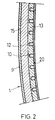
- Figure 2 shows a detail in section of the tub taken along the plane indicated.
- Figures 3 and 4 each represent views of a device for securing the lid of the tub.
- FIG. 5 shows a full, simplified section of the centrifuge.
- Figures 6, 7, 8 and 9 are each details of embodiment of the internal plating, in which the grooves are made, in a centrifuging tub according to the object of the present invention.
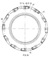
- Figures 10 and 11 show schematically an elevation view with a partial section and a lower view of a centrifuging machine tub with discharge from below.
- Figure 12 shows a detail in section of the centrifuging tub represented in figures 10 and 11.
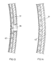
- Figure 13 and 14 are each sections of the tub shown in figures 10 and 12 taken along the lines shown.
- Figure 15 shows a longitudinal section of the tub which is shown in figures 10-12.
- FIGS 16, 17 and 18 are each details of the lid closing systems provided as a preferred embodiment of the present invention.
- Figure 19 represents a section taken along the plane indicated.
- the centrifuge which forms the object of the present invention comprises a tub 1 linked to a central axis 2 so that it can rotate by means of a conventional drive system 3, said tub being provided with an incomplete upper lid 4 and being enclosed inside a collecting casing consisting of a body in the form of a second fixed surrounding tub 5 provided with lower outlet pipes 6 and an upper closing lid 7.
- the liquid to be treated is fed via a pipe 8 from the upper part of the tub, since the lid 4 has a wide central opening.
- the side wall 9 of the tub has on its internal surface 10 a layer of synthetic resin 13 with multiple grooves 12 adopting from its bottom 14 a slight outwards inclination, that is, from the bottom to the top, in order that the liquid to be separated may run along said grooves, arriving to the upper part of the tub 9 for its removal through the outlet grooves 11.
- Said layer of synthetic material coating 13 may be applied to the rest of the exposed surfaces of the tub as well as to other elements, the coating layers 15 on the outside of the tub and 16 on the upper edge regions thereof being shown in the drawings.
- the centrifuge is provided with a incomplete upper lid 4, with radial devices for securing it quickly by means of a system of wedges 17 and fixed supports 18, and is provided inside with means, which are specially integrated into the upper ring 19, for securing the filter bag 20 for eliminating the residues which remain inside the tub.
- the longitudinal grooving of the walls of the tub is made using fitted plating elements of a suitable material and which have a corrugated structure forming ribs and grooves, such that the grooves have the characteristics described above in terms of their inclination for the evacuation of the particles to be separated.
- the pieces of plating represented generally by the numbers 21, 22, 23 and 24 are provided with grooves 25, 26, 27 and 28 respectively, which fit by the bottom of said grooves to the inner wall of the centrifuge tub, labelled 29, 30, 31 and 32 respectively in the embodiments shown.
- the collecting bag is arranged in contact with the crests or ribs of the corrugated plating, which may have different structures such as rectangular as in figure 6 with crests or ribs 33, or trapezial as in figure 7 with crests 34, trapezial with an acute-angled bottom and flat crests 35, or corrugated shapes whose crests 36 may also be curved.
- the machine which forms the object of the present invention may be further provided with a lower discharge tub, as is shown in figures 10, 11 and 12.
- Said tub 37 is provided with lower openings 38 for eliminating the solid particles to be separated, in this case a number of holes 39 for the evacuation of the liquid being made in the side wall at an intermediate height thereof, and in this case the internal walls of the tub 37 being provided with an upper grooved area 40 and another lower grooved area 41 which start, respectively, at the upper edge and at the lower edge of the tub and which are gently inclined towards the central part in order that the liquid to be separated tends to move towards said central part where the outlet openings 39 are located, of which there can be any number.
- a separating ring 42 is arranged in front of the holes 39, at a sufficient distance relative to said holes, to help support the inner collecting cloth member 43.
- the layer of material which is deposited on the side wall 37 of the centrifuging tub is removed by means of a known type of device, not shown, consisting of a scraper which can be moved axially and radially.
- the collecting cloth 43 is retained above and below by means of the arrangement of retaining rings 44 each inserted into grooves in the walls of the tub.
- the present invention further foresees a preferred embodiment of the system for closing the lid of the centrifuge tub, as is shown in figures 16 to 18.
- Said closing device comprises through bolts 45 which pass through both the lid 46 of the tub and the lower ring 47, the head or upper part of said bolts being conical and rounded 48 to improve the self-centring of the lid 46 during fitting, and the lower part 49 being threaded for fixing to a securing nut 50.
- the upper part of the bolt is provided with two opposing transverse cuts or grooves 51 and 51' onto which fits a flat-walled latch or fastener 52 which rotates about a fixed bolt 53 and which has a mouth 54, figure 17, that has inclined edges to improve its entrance onto the groove and a shape which is complementary thereto.
- the latch 52 can be easily moved laterally by means of a handle 55 in order to open and close it. After it has been closed, the safety fastenings are applied by means of the nut 50.
- the improvement consisting in the multiple grooves in the internal wall of the baskets or tubs of the centrifuges may also be used in horizontal centrifuges.
- the constitution of the centrifuge as has been described results in highly efficient operation, both in terms of the protection of the tub walls and the avoidance of blockages and obstructions, thereby reducing the customary and bothersome tasks of maintenance to a minimum.
Landscapes
- Centrifugal Separators (AREA)
Applications Claiming Priority (2)
| Application Number | Priority Date | Filing Date | Title |
|---|---|---|---|
| ES9301380U ES1024282Y (es) | 1993-05-20 | 1993-05-20 | Maquina centrifugadora perfeccionada. |
| ES9301380U | 1993-05-20 |
Publications (2)
| Publication Number | Publication Date |
|---|---|
| EP0625374A2 true EP0625374A2 (de) | 1994-11-23 |
| EP0625374A3 EP0625374A3 (de) | 1995-05-10 |
Family
ID=8282275
Family Applications (1)
| Application Number | Title | Priority Date | Filing Date |
|---|---|---|---|
| EP94500087A Withdrawn EP0625374A3 (de) | 1993-05-20 | 1994-05-18 | Verbesserte Zentifuge. |
Country Status (2)
| Country | Link |
|---|---|
| EP (1) | EP0625374A3 (de) |
| ES (1) | ES1024282Y (de) |
Cited By (2)
| Publication number | Priority date | Publication date | Assignee | Title |
|---|---|---|---|---|
| WO2003033163A1 (en) | 2001-10-18 | 2003-04-24 | Wdt (Engineers) Pty Ltd | Continuous centrifuge |
| RU2287374C2 (ru) * | 2004-12-06 | 2006-11-20 | ФГОУ ВПО Курганская государственная сельскохозяйственная академия им. Т.С. Мальцева | Центрифуга для разделения соевого развара на соевую основу и окару |
Family Cites Families (7)
| Publication number | Priority date | Publication date | Assignee | Title |
|---|---|---|---|---|
| GB377578A (en) * | 1932-01-30 | 1932-07-28 | Watson Laidlaw & Company Ltd | Improvements in centrifugal machines or hydro-extractors |
| BE415313A (de) * | 1935-07-16 | |||
| DE1632308A1 (de) * | 1967-09-28 | 1970-08-27 | Buckau Wolf Maschf R | Zentrifugentrommel |
| US3669879A (en) * | 1969-12-15 | 1972-06-13 | Dresser Ind | Fluid separation apparatus and method |
| DE2228889A1 (de) * | 1972-06-14 | 1974-01-03 | Braunschweigische Masch Bau | Schleudertrommel fuer zentrifugen, insbesondere zuckerzentrifugen |
| US4196443A (en) * | 1978-08-25 | 1980-04-01 | Rca Corporation | Buried contact configuration for CMOS/SOS integrated circuits |
| DE3610229A1 (de) * | 1986-03-26 | 1987-10-01 | Gerlach Hildburg | Mehrstufige schubzentrifuge |
-
1993
- 1993-05-20 ES ES9301380U patent/ES1024282Y/es not_active Expired - Fee Related
-
1994
- 1994-05-18 EP EP94500087A patent/EP0625374A3/de not_active Withdrawn
Cited By (4)
| Publication number | Priority date | Publication date | Assignee | Title |
|---|---|---|---|---|
| WO2003033163A1 (en) | 2001-10-18 | 2003-04-24 | Wdt (Engineers) Pty Ltd | Continuous centrifuge |
| RU2279319C2 (ru) * | 2001-10-18 | 2006-07-10 | Вдт (Инджинирс) Пти Лтд. | Центрифуга непрерывного действия |
| US7208048B2 (en) | 2001-10-18 | 2007-04-24 | Wdt (Engineers) Pty. Ltd. | Continuous centrifuge |
| RU2287374C2 (ru) * | 2004-12-06 | 2006-11-20 | ФГОУ ВПО Курганская государственная сельскохозяйственная академия им. Т.С. Мальцева | Центрифуга для разделения соевого развара на соевую основу и окару |
Also Published As
| Publication number | Publication date |
|---|---|
| EP0625374A3 (de) | 1995-05-10 |
| ES1024282U (es) | 1993-08-01 |
| ES1024282Y (es) | 1994-04-01 |
Similar Documents
| Publication | Publication Date | Title |
|---|---|---|
| US8808155B2 (en) | Centrifuge bowl with liner material molded on a frame | |
| AU665308B2 (en) | Extraction of mercury and gold from mine tailings | |
| US5149432A (en) | Centrifuge for separating liquids of different specific gravities | |
| CA2453975C (en) | Deflector ring for a self-discharging centrifuge | |
| EP0897752B1 (de) | Zentrifuge mit heftig bewegtem Feststoffkuchen | |
| US2138468A (en) | Centrifugal separator | |
| CA2160645C (en) | Centrifugal separator with conical bowl section and axially spaced recesses | |
| CN103785548A (zh) | 通过准连续的离心机运动从小吃或快餐食品中分离烹调油的方法和装置 | |
| RU2257835C2 (ru) | Сепаратор для мусороуборочной машины вакуумного действия | |
| US5958235A (en) | Continuous-feed filtering- or screening-type centrifuge with reslurrying and dewatering | |
| EP0625374A2 (de) | Verbesserte Zentifuge | |
| US3647135A (en) | Continuously operating centrifugal separator | |
| US2594445A (en) | Centrifugal machine and process | |
| US4350282A (en) | Self-purging centrifuge | |
| US5036623A (en) | Tumbler for polishing small parts such as ammunition cases and the like | |
| US3108067A (en) | Centrifugal apparatus | |
| JP6840011B2 (ja) | 固形物を湿式機械的に分離するための補助的な外側の螺旋体を備えたスクリュー遠心分離機 | |
| US3552575A (en) | Centrifuge | |
| GB1569520A (en) | Solid bowl screw centrifuges | |
| JP2007136455A (ja) | 遠心機カートリッジ | |
| US3432092A (en) | Self-cleaning centrifugal separator | |
| JP2017196615A5 (de) | ||
| WO2020184591A1 (ja) | 卵殻と卵殻膜との分離方法及び分離装置 | |
| JP2007160220A (ja) | 遠心分離法を用いたメカニカルフィルター装置及びメカニカルフィルターのための遠心分離方法 | |
| JPH08501725A (ja) | フィルタ装置 |
Legal Events
| Date | Code | Title | Description |
|---|---|---|---|
| PUAI | Public reference made under article 153(3) epc to a published international application that has entered the european phase |
Free format text: ORIGINAL CODE: 0009012 |
|
| AK | Designated contracting states |
Kind code of ref document: A2 Designated state(s): AT BE CH DE DK ES FR GB IT LI NL SE |
|
| PUAL | Search report despatched |
Free format text: ORIGINAL CODE: 0009013 |
|
| AK | Designated contracting states |
Kind code of ref document: A3 Designated state(s): AT BE CH DE DK ES FR GB IT LI NL SE |
|
| RIN1 | Information on inventor provided before grant (corrected) |
Inventor name: ALBERTI COMELLAS, JAUME |
|
| 17P | Request for examination filed |
Effective date: 19950707 |
|
| 17Q | First examination report despatched |
Effective date: 19980209 |
|
| STAA | Information on the status of an ep patent application or granted ep patent |
Free format text: STATUS: THE APPLICATION IS DEEMED TO BE WITHDRAWN |
|
| 18D | Application deemed to be withdrawn |
Effective date: 19980620 |