EP0625301B1 - Tape packaging system with removable covers - Google Patents
Tape packaging system with removable covers Download PDFInfo
- Publication number
- EP0625301B1 EP0625301B1 EP93902748A EP93902748A EP0625301B1 EP 0625301 B1 EP0625301 B1 EP 0625301B1 EP 93902748 A EP93902748 A EP 93902748A EP 93902748 A EP93902748 A EP 93902748A EP 0625301 B1 EP0625301 B1 EP 0625301B1
- Authority
- EP
- European Patent Office
- Prior art keywords
- tape
- component
- pallet
- set forth
- projections
- Prior art date
- Legal status (The legal status is an assumption and is not a legal conclusion. Google has not performed a legal analysis and makes no representation as to the accuracy of the status listed.)
- Expired - Lifetime
Links
Images







Classifications
-
- H—ELECTRICITY
- H05—ELECTRIC TECHNIQUES NOT OTHERWISE PROVIDED FOR
- H05K—PRINTED CIRCUITS; CASINGS OR CONSTRUCTIONAL DETAILS OF ELECTRIC APPARATUS; MANUFACTURE OF ASSEMBLAGES OF ELECTRICAL COMPONENTS
- H05K13/00—Apparatus or processes specially adapted for manufacturing or adjusting assemblages of electric components
- H05K13/04—Mounting of components, e.g. of leadless components
- H05K13/0417—Feeding with belts or tapes
-
- H—ELECTRICITY
- H05—ELECTRIC TECHNIQUES NOT OTHERWISE PROVIDED FOR
- H05K—PRINTED CIRCUITS; CASINGS OR CONSTRUCTIONAL DETAILS OF ELECTRIC APPARATUS; MANUFACTURE OF ASSEMBLAGES OF ELECTRICAL COMPONENTS
- H05K13/00—Apparatus or processes specially adapted for manufacturing or adjusting assemblages of electric components
- H05K13/02—Feeding of components
- H05K13/021—Loading or unloading of containers
-
- H—ELECTRICITY
- H05—ELECTRIC TECHNIQUES NOT OTHERWISE PROVIDED FOR
- H05K—PRINTED CIRCUITS; CASINGS OR CONSTRUCTIONAL DETAILS OF ELECTRIC APPARATUS; MANUFACTURE OF ASSEMBLAGES OF ELECTRICAL COMPONENTS
- H05K13/00—Apparatus or processes specially adapted for manufacturing or adjusting assemblages of electric components
- H05K13/02—Feeding of components
- H05K13/0215—Interconnecting of containers, e.g. splicing of tapes
-
- Y—GENERAL TAGGING OF NEW TECHNOLOGICAL DEVELOPMENTS; GENERAL TAGGING OF CROSS-SECTIONAL TECHNOLOGIES SPANNING OVER SEVERAL SECTIONS OF THE IPC; TECHNICAL SUBJECTS COVERED BY FORMER USPC CROSS-REFERENCE ART COLLECTIONS [XRACs] AND DIGESTS
- Y10—TECHNICAL SUBJECTS COVERED BY FORMER USPC
- Y10T—TECHNICAL SUBJECTS COVERED BY FORMER US CLASSIFICATION
- Y10T29/00—Metal working
- Y10T29/53—Means to assemble or disassemble
- Y10T29/5313—Means to assemble electrical device
- Y10T29/53174—Means to fasten electrical component to wiring board, base, or substrate
- Y10T29/53178—Chip component
-
- Y—GENERAL TAGGING OF NEW TECHNOLOGICAL DEVELOPMENTS; GENERAL TAGGING OF CROSS-SECTIONAL TECHNOLOGIES SPANNING OVER SEVERAL SECTIONS OF THE IPC; TECHNICAL SUBJECTS COVERED BY FORMER USPC CROSS-REFERENCE ART COLLECTIONS [XRACs] AND DIGESTS
- Y10—TECHNICAL SUBJECTS COVERED BY FORMER USPC
- Y10T—TECHNICAL SUBJECTS COVERED BY FORMER US CLASSIFICATION
- Y10T29/00—Metal working
- Y10T29/53—Means to assemble or disassemble
- Y10T29/5313—Means to assemble electrical device
- Y10T29/53174—Means to fasten electrical component to wiring board, base, or substrate
- Y10T29/53183—Multilead component
-
- Y—GENERAL TAGGING OF NEW TECHNOLOGICAL DEVELOPMENTS; GENERAL TAGGING OF CROSS-SECTIONAL TECHNOLOGIES SPANNING OVER SEVERAL SECTIONS OF THE IPC; TECHNICAL SUBJECTS COVERED BY FORMER USPC CROSS-REFERENCE ART COLLECTIONS [XRACs] AND DIGESTS
- Y10—TECHNICAL SUBJECTS COVERED BY FORMER USPC
- Y10T—TECHNICAL SUBJECTS COVERED BY FORMER US CLASSIFICATION
- Y10T29/00—Metal working
- Y10T29/53—Means to assemble or disassemble
- Y10T29/5313—Means to assemble electrical device
- Y10T29/53261—Means to align and advance work part
Definitions
- the present invention relates to multi-walled tape component carriers, e.g. for odd components (i.e. size, geometry or production run length), and a tape component packaging system apparatus and, in particular, to a wound tape, component feeder assembly for packaging single or multiple small components, especially electronic components at seriatim covered, tape storage locations in indexed relation to each other and the tape.
- odd components i.e. size, geometry or production run length
- a wound tape, component feeder assembly for packaging single or multiple small components, especially electronic components at seriatim covered, tape storage locations in indexed relation to each other and the tape.
- Varieties of tape media have been developed for storing and conveying components within varieties of packaging systems which sequentially remove or mount the components to the tape carrier.
- Many of the tape carriers provide a substrate that includes one or more rows of apertures which mate with system conveyor drive sprockets (see WO-A-9 004 915). The system driver thereby appropriately conveys the tape contents to particular sites within the system.
- the packaged components of many prior systems have been limited to components of uniform size and shape.
- components are secured to the tape carrier with removeable fastener or binding strips which longitudinally coincide with the tape carrier and which are secured to the carrier at either side of each component.
- the binding strips can be mounted to one or both of the upper and lower tape surfaces.
- the binding strips are treated as waste, although they may be re-used in certain arrangements. Examples of some of such systems and tapes can be found upon directing attention to U.S. Patent Nos. 3,135,375; 3,129,814; 3,140,773; 3,920,121; and 4,852,737.
- the tape carrier includes flap portions which are hinge coupled along one edge to the tape carrier. An opposite or other edges either permanently or detachably mount to the carrier. The contained components are thus insertable either from the side or vertically from above the tape.
- Various of such assemblies can be found upon directing attention to U.S. Patent Nos. 4,621,486; 4,631,897; and 4,867,308.
- a variety of tape systems have also been developed which provide component storage compartments.
- the compartments are formed either by way of thickened tape substrates or cavities which are formed into the substrate.
- thermal formed storage compartments are not particularly molded to the configuration of the contained component. Some require a separate, co-extensive and non-reusable binding tape.
- the binding tape of the 4,708,245 patent is reusable, but the longitudinal fasteners must be separately secured to the tape carrier to restrain one to the other; correspondingly, the tape fabrication costs and complexity of component extraction equipment increase proportionately.
- the tape carrier should provide lead wire support apertures and/or include means for indexing and registering each component to the carrier generally or within a tape storage location containing a number of components.
- Applicant has developed a carrier which provides for closely spaced component storage locations.
- Multi-walled tape component carriers according to the invention are defined in independent claims 1 and 30.
- a tape component packaging system apparatus according to the invention is defined in independent claim 14.
- the storage locations may be conformably configured to the components to be stored and permit mounting of multiple components at each storage location.
- Each location is freely accessible from all directions for loading/unloading or test, upon removal of a conformal cover which is replaced after each access; thus minimizing waste.
- Each storage location further includes a component support pallet which can be replaced, when worn, or substituted to accommodate another component type, thus reducing attendant inventory costs to the tape manufacturer.
- the taper carrier thereby has a relatively long life, may be re-used and may accomodate a wide variety of sizes and shapes of components.
- the invention is useable alone or in any system configuration wherein multiple odd component feeders are required to cooperate with a component supply source or a work object station.
- a component supply source or a work object station may comprise a printed circuit board assembly station and the former might comprise an electronics component packing station.
- each of the feeder or server assemblies provides a housing including a microprocessor controller and associated positionally indexed electro-mechanical controls.
- Mechanical control assemblies plug mount to an interface portion of the housing in a fashion similar to the printed circuit boards.
- the aft end of the feeder housing provides upper and lower tape component cartridge receiving tracks.
- a spool or reel drive assembly projects from the housing to frictionally cooperate with a component containing tape carrier wound about the reel drive assembly advances a tape leader or the trailer end of the tape carrier to a splicing assembly where mating connector blocks are coupled to interconnect the supply and take-up cartridges.
- the splicing assembly includes means for actuating a splice block interconnect.
- a driven sprocket tape which mates with apparatus spaced along the tape carrier, projects from the feeder housing in relation to guide rails for otherwise conveying the component containing tape carrier along the housing.
- a cover removal assembly is vertically and longitudinally actuable to release the cover from the tape carrier; retain the cover away from filling or extraction operations and replace the cover upon the completion of component filling or extraction.
- component manipulation otherwise occurs at lift-and-locate means which includes clamp means for restraining the tape to the housing and means for inserting a conformal component support pallet to the tape carrier.
- the insertion means may include electrical or mechanical test fixtures which test one or more contained components.
- an overlying gantry framework supports an interchangeable tool changer assembly.
- the tool changer supports a multi-faceted, rotating tool head that contains a number of multi-fingered tools and means for positioning a specific tool at an operating position.
- a gripping means expands and contracts the tool fingers to grasp and release the components.
- the tape substrate provides a plurality of seriatim component storage sites or housings. Each site may include resilient fastener means for coupling to vertically aligned component support pallets.
- the pallet defines the bottom of the housing.
- each pallet provides appropriate apertures, formed projections and/or cavities to support one or more components and associated leads in a flat or edge-mounted condition.
- Each cover similarly contains conformed surfaces for mating with the contained components and complementary means for resiliently containing the cover at each storage site to the annulus and pallet.
- Figure 1 is a plan drawing of one multi-feeder, packaging system and cartridge support server.
- Figure 2a is a plan drawing of a component placement work station or workcell, supported by a number of component feeders.
- Figure 2b is a plan drawing of an alternative workcell and arrangement of the component feeders and control arm.
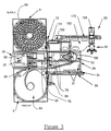
- Figure 3 is an elevation drawing shown in partial cutaway of one of the component feeder stations including a tool head containing gantry.
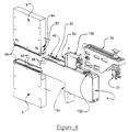
- Figure 4 is a perspective drawing of a component feeder station wherein the tape cartridges and tool head and gantry are shown in exploded assembly.
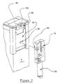
- Figure 5 is a perspective drawing of the tape cartridge door opener assembly.
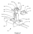
- Figure 6 is a perspective drawing shown in exploded assembly of the tape splicing assembly and the tape splice blocks.
- Figure 7 is a perspective drawing of the connected tape ends.
- Figure 8 is a perspective drawing of the clutch driven, pinned drive tape assembly.
- Figure 8a is a detailed cross section drawing of a portion of the drive tape in relation to a typical tape carrier.
- Figure 9 is a perspective drawing of the cover removal assembly shown in retracted relation to the tape carrier clamping assembly.
- Figure 10 is a detailed perspective drawing of the tape carrier clamping assembly.
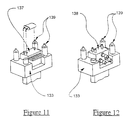
- Figure 11 is a perspective drawing of an electronic test platform useable with the assembly of Figure 10.
- Figure 12 is a perspective drawing of a pneumatic/fluid test platform useable with the assembly of Figure 10.
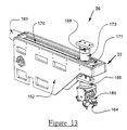
- Figure 13 is a perspective drawing of the gantry and multi-faceted component tool head.
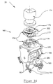
- Figure 14 is a detailed perspective drawing of the multi-faceted tool head and the tool head changer.
- Figure 15a is a detailed perspective drawing of the tool head changer of Figure 14.
- Figure 15b is a detailed perspective drawing of a high current electrical connector to the tool head changer.
- Figure 15c is a detailed perspective drawing of the multi-faceted tool head.
- Figure 15d is a side elevation drawing of a four-position tool head.
- Figure 15e is a side elevation drawing of a five-position tool head.
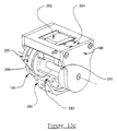
- Figure 15f is a detailed perspective drawing shown in cutaway of the parallel gripper portion of the tool head.
- Figure 16 is a perspective drawing shown in exploded assembly drawing of a component tape cartridge.
- Figure 17 is a perspective drawing shown in exploded assembly of one palletized component storage location.
- Figure 18 is a perspective drawing of a section of tape carrier including pallets for supporting dual-in-line (DIP) components.
- DIP dual-in-line
- Figure 19 is a perspective drawing of a section of tape carrier including pallets having resilient component grasping projections.
- Figure 20 is a perspective drawing of a section of tape carrier including component fastener clips, with friction walled projections.
- Figure 21 is a perspective drawing of a section of a tape carrier wherein the pallet includes projections for indexing and supporting a plurality of populated, edge mounted, thick film hybrid components.
- Figure 22 is a perspective drawing of a section of a tape carrier wherein the pallet includes indexed recesses for supporting edge mounted components and provides spacing allowing component pickup.
- Figure 23 is a perspective drawing of a section of a tape carrier wherein the pallet includes a multi-apertured recess for receiving surface mount components.
- Figure 24 is a perspective drawing of a section of a tape carrier, similar to Figure 23 but including lead wire spacer tabs.
- Figure 25 is a functional block diagram of the plug-mounted hydraulic/pneumatic and electrical controller.
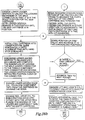
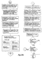
- Figure 26a, 26b, and 26c show generalized flow diagram of controller operation.
- FIG. 1 a top plan view is shown of the organizational layout of one possible, relatively sophisticated odd component packaging or feeder system 2.
- the system 2 incorporates numerous tape cartridge feeder stations or feeders 4 of the present invention. The particular details of the feeder station 4 will be discussed in detail in the following description.
- a number of feeder stations 4 are positioned between a transversely mounted cartridge server conveyer 5, a cartridge loading means 6 and a component conveyor 8 or assembly station (reference Figures 2a, 2b).
- the server 6 conveys cartridges 9 to and from each of the individual feeder stations 4 in response to control signals identifying the filled/empty status of each of the cartridges 9.
- the server 6 in response to the control signals induces a driven lead screw assembly 10 to positionally align a cartridge carrier 12 in relation to a particular one of the plurality of feeder stations 4.
- a slide arm 14 of the carrier 12 is activated to induce an empty slide tray 16 to extend and engage one of the component cartridges 9 of the selected feeder station 4.
- the cartridge 9 can either be filled or empty.
- the slide tray 16 Upon grasping the cartridge 9, the slide tray 16 is retracted and withdrawn into registration with the carrier 12. Either the same or a second slide arm 14 containing a complementary filled or empty cartridge 9 is next indexed into alignment with the feeder 4 and extended to cause its cartridge to engage with the feeder 4.
- the parallel server conveyor 5 automatically replenishes the server carrier 12 with appropriate cartridges and extracts the populated or depleted cartridges 9. In a less automated setting, one or more of the foregoing functions can be performed manually.
- each feeder 4 may include a gantry mounted pick-and-place assembly 26 (reference Figure 3) to select parts from the conveyor 8 and populate its cartridge 9.
- a plurality of assemblies such as printed circuit boards (PCB) 7, may be conveyed in controlled relation to each feeder 4 or may be stationed at a number of component placement stations, where the PCB's are populated with parts extracted from the tape cartridges 9 of the feeder stations 4.
- PCB printed circuit boards
- each feeder station 4 may provide a particular component type, which may be the same or different from each neighboring station 4. Regardless, each feeder station 4 selectively extracts the components of the cartridges 9 and positionally mounts the components to each PCB 7. Upon incrementally advancing each PCB 7 past the feeder stations 4, each PCB 7 can be substantially populated with minimal human intervention.
- a component placement station 19 is shown wherein nine feeder stations 4 are positioned relative to a transverse conveyer 20 including printed circuit boards 22.
- the PCBs 22 are populated via a single robotic control arm 24 having a single tool head which selects appropriate components from each feeder station 4 under system control.
- the feeder stations 4 of the system 2 each included a gantry arm assembly 26 containing a multi-faceted pick-and-place tool head 33, which will be described below.
- Figure 2b depicts an alternative component placement station 19.
- a single track mounted gantry assembly 29 which contains a single multi-faceted tool head (not shown).
- Tool head movement is cartesionally directed above the feeders 4 and conveyor 20. That is, the gantry 29 moves longitudinally along the rails 27 and 31, while the tool head extends and retracts along the gantry and laterally of the conveyor 20.
- Specific gantry and tool head movement is determined under system control relative to the location of the component pallet, the PCBs 22 being populated and the available components at the feeders 4.
- each feeder 4 contains a multi-faceted, tool head 33.
- the structure of each feeder 4 and station can be modified, depending upon the system requirements.
- each feeder 4 is configured about a frame superstructure that is covered with a sheet metal cabinet or housing 28.
- the housing 28 contains the feeder control assemblies (i.e. pneumatic/hydraulic and electric), a control panel 30 and the associated tape handling assemblies which are described in greater detail below.
- the control panel 30 interacts with a multi-board, microprocessor based electronic controller 32 and associated solenoid activated, pneumatic and hydraulic controls, reference Figure 25.
- twelve solenoids 31 are provided with each feeder 4.
- a plurality of plug-in ports 38 permit coupling appropriately sized pneumatic and electrical supply sources and communication lines (not shown) to power the feeder 4.
- Mating couplers connected to a service table (not shown) interface with the feeder at locating pins 34 which extend from a support base 36.
- Figure 26 discloses a functional flow diagram of the operational source code implemented in on-board PROM memory 40. Additional instructions can be programmed by the system user via a micro computer 42 into memory associated with the microprocessor controller board 44.
- control panel 30 Mounted to a forward and operator accessible surface of the housing 28 is the control panel 30.
- a plurality of manual control switches, push buttons, pilot lights and tne like are mounted to the panel and interface with the microprocessor board 5 44 via an input board.
- Figure 25 depicts more of the details of the manual controls. Most typically, the controls are accessed during initial system and feeder setup or manual operation, such as when initially splicing the tape cartridges together or wnen performing maintenance on the feeder.
- dove tail slide track assemblies 46 Secured to the upper and lower aft surfaces of the housing 28, just forward of the control panel 30, are dove tail slide track assemblies 46, reference Figure 4.
- the track assemblies 46 receive and contain the supply and take-up component cartridges 48.
- Two slide assemblies 46 are provided which are identical to one another, although only the upper assembly is depicted at Figure 4.
- the present feeders 4 are normally operable in a cyclic fashion, neither one of the cartridge positions continuously functions as a supply or take-up cartridge. Rather, the positions alternate relative to component flow through tne feeder assemblies 4. That is and as will become more apparent hereinafter, the tape direction alternates with each cycle. For example and as depicted at Figure 3, as a filled tape moves from the upper "Supply" cartridge 9 to the lower, "Take-up" cartridge 9, during the first half of a cycle, the components are removed.
- a tape leader and connector block are eventually extracted and positioned for subsequent operations to be described below.
- the lower cartridge 9 then contains the depleted tape and is removed.
- a full component cartridge 9 is then mounted to the lower cartridge position and spliced to the upper, now empty supply cartridge which becomes the take-up cartridge and the drive direction is reversed. Handling time of the populated and empty cartridges 9 is thus reduced. For certain applications, it may however be desired to provide a single direction parts flow, with attendant increased cartridge handling.
- FIG. 1 depicts an automatic cartridge server assembly 6.
- the server 6 includes a lead screw 10, which along with a pair of slide rails 11 supports a screw follower mounted slide carrier 12 and a pair of cartridge support trays 16.
- the server 6 may include duplicate arrangements of upper and lower cartridge trays 16 for achieving the necessary loading/unloading at each feeder station.
- Control signals which typically are of a pulse width modulated variety are applied from the controller 32 to drive a stepper motor 50 coupled to the lead screw 6.
- the slide trays 16 are thereby appropriately aligned with the depleted and full cartridges 9.
- the empty tray is extended and retracted to remove an empty cartridge 9 and the other tray re-loads the feeder 4 with a full cartridge. Tray movement is controlled to insure that the cartridges 9 are locked to the housing 28 and a forward surface adjacent a cartridge accessing station 54 (reference Figure 4).
- the drive wheels are biased a sufficient height to extend interiorly of the cartridges 9 at matching cartridge apertures 62 to contact and rotate the peripheral surfaces of a tape reel 68 mounted within each cartridge 9, reference Figure 3.
- the drive wheels 60 are driven via a drive assembly 70 and reel drive motor M2 (reference Figure 25).
- a dual drive assembly 70 is particularly provided which can be resiliently biased up or down to appropriately drive the tape of the upper or lower cartridge 9, until a sprocket tape drive assembly 72 captures the tape. This occurs in a region slightly forward of the cartridges 9 and will be described in greater detail below.
- each cartridge 9 Mounted forward of the reel drive assembly 70, adjacent the forward face of each cartridge 9 are upper and lower cartridge access or tape splicing stations 54.
- the splicing stations are identical to each other.
- Each includes a cartridge door opening assembly 76 and a splicing assembly 78. The specific constructional details of the assemblies 76 and 78 can be seen upon reference to Figures 5 and 6.
- Each door opener assembly provides a projecting lug 80 which mates with an aperture 82 formed in a spring loaded cartridge slide door 84.
- the lug 80 is vertically operable via an associated solenoid and pneumatic or hydraulic directed piston 86 to raise and lower the slide door 84 in response to signals from the controller 32.
- the lower edge of the door 84 is thereby released from a groove 88 formed within a surface of a female coupler or splice block 90.
- the splice block 90 is attached to the leading end of a tape leader 92 secured to the internal tape reel 68. More of the details of the construction of each cartridge 9, tape leader 92 and splice blocks 90 can be seen upon reference to Figures 6, 7, 16 and 17.
- the tape leader 92 is advanced to the splicing assembly 78 via a threader assembly 98.
- Actuation of a pair of opposed threader cylinders 99 extends and retracts the splicing assembly causing it to move to and fro along paired sets of guide rods 79.
- a vertical control cylinder 74 causes a pair of pins 94 to grasp the block 90 and contract a pair of spring biased fingers 102.
- Subsequent actuation the cylinders 99 aligns and directs the tape leader 92 along lateral edge guides which rise from the surface of the housing 28 to loosely constrain and confine the leader travel, without allowing the leader to buckle.
- a male splice block 100 is concurrently restrained adjacent the splicing assembly 78 from the previous full cartridge 9, which now comprises the take-up cartridge.
- the advancement of the female connector block 90 via the cylinders 99 causes the connector and splice blocks 90 and 100 to couple. That is, the fingers 102 of the male splice block 100, which include tapered fore-ends 104 and a flange 106, are inserted within the mating longitudinal aperture 108 of the female splice block 90. With a subsequent removal of the pins 94, the fingers 102 expand to cause the flanges 106 to couple one block to the other. The splicing assembly 78 is then released from the coupled blocks 90, 100.
- the pins 94 contract the fingers 102 to release the splice blocks from one another.
- the pin carriage is then retracted to separate the blocks.
- the actuation of the cylinders 99 also advances the tape carrier 92 onto the tape drive assembly 72.
- the reel drive 70 With the release of the splice blocks 90, 100, the reel drive 70 is engaged to the depleted cartridge to induce the leader 92 to be taken up into the cartridge 9. The cartridge 9 can then be removed and replaced with a new cartridge 9.
- the male splice block 100 meanwhile is restrained at the splice station 78 and to the sprocket tape drive 72.
- the slide door 84 of the new cartridge is next retracted and the tape leader 92 is advanced by the reel drive 70 to achieve coupling.
- the cartridge take-up and supply positions alternate, however, the positions of the male and female splice blocks remain constant relative to the splice station 78.
- the tape drive assembly generally comprises a pair of endless, metal drive bands 112 which include a plurality of dual purpose, drive lugs 113 and drive pins 114.
- the pins 114 mate with apertures 115 let into the lateral edges of the tape 110.
- the drive bands 112 are wound about and in frictional contact with three pairs of drive wheels 116, 118 and 120.
- the drive wheels 116 contain recesses which mate with the drive lugs 113 and are driven via a notched belt 122, pulley 124 and stepper motor 126.
- the other pairs of wheels 118 and 120 act as idler wheels and are free spinning with the bands 112.
- Slippage is thereby minimized at any of the drive wheels 116, 118 or 120, which slippage could translate at the control circuitry into component misalignment (either real or apparent) relative to the splicing assembly 74, cover removal assembly 130 and lift and locate assembly 132.
- the bands 112 can slip relative to the tape 110 or stepper motor 126 to prevent breaking the tape carrier.
- the amount of slippage is dependent upon drive band tension, which is adjustable at a tensioner assembly.
- Slippage induces an alarm condition and, depending upon the amount of slippage, can be automatically corrected by the controller 32.
- the controller 32 If the tape 110 become disengaged from the drive bands 112, the loss of tension causes the controller 32 to stop drive power and annunciate an appropriate operator alarm.
- the tape 110 is advanced past the cover removal assembly 130 to the lift and locate station or assembly 132.
- a detailed perspective drawing is shown of the assembly 130 which extends above the housing 28 and the path of the tape carrier 110, forward of the splicing assembly 78.
- the principal operation performed by the assembly 130 is to remove the Faraday cage or cover 134 (reference Figure 7) from each of the plurality of storage sites or component compartments 135 located on the tape carrier 110.
- the cover removal assembly 130 includes an extractor head 140.
- the extractor head 140 is capable of vertical and longitudinal movement via a pair of fluid controlled cylinders.
- a cylinder 131 mounted beneath the cover 139 (reference Figure 3) controls longitudinal movement and a cylinder 143 secured to the head 140 controls vertical movement of the head 140.
- Cover removal is particularly effected upon directing each component compartment into alignment with the lift and locate assembly 132.
- the extractor head 140 is then extended and vertically lowered with sequential control of the cylinders 141, 143 such that a number of contained fingers 142 are projected through mating apertures 144 of the cover 134.
- the fingers 142 are lowered, they flex the cover 134 to disengage the cover from mating tabs formed into the sidewalls of a raised ring that projects from the tape 110 (reference Figure 17) to release the cover 134 from the tape 110.
- the fingers 142 support the cover 134, which is then vertically retracted and cleared to one side, away from further operations.
- the component storage compartment 135 is then accessed to either fill the compartment 135 or extract contained parts.
- FIG. 11 and 12 depict test fixtures 137 and 138 which contain electrical and/or pneumatic and fluid connectors which permit cursory electrical and mechanical integrity tests of each component.
- the clamping assembly 136 includes a pair of clamps 152 which are mounted to rotate in response to the extension and retraction of a pair of cylinders 154 mounted to each side of the tape 110.
- the lift and locate assembly 132 is actuated to raise a pallet support platform 133 (reference Figures 11 and 12).
- a number of pins 139 project from the platform to engage apertures 156 formed in the outer periphery of the component pallet.
- the pallet 146 is thereby securely constrained between the pins 139 and clamps 152.
- the pallet 146 is restrained to a known reference location and relative to which the previously mentioned robotic arm 24 or the gantry mounted, multi-faceted tool head assembly 33 can access the contained components.
- the components can also be simultaneously tested at the fixtures 137 as they are loaded or removed.
- the tool head assembly 33 contains a number of tool heads which typically contain pick-and-place fingers 164.
- the fingers 164 are secured to a gripper assembly 165 that determines finger movement.
- Each gripper 165 is secured to the tool head 33 via a coupler assembly 166.
- the tool head assembly 33 is supported to the gantry 26 at a pair of driven lead screws 168 and 170.
- the assembly 33 is horizontally extensible via a servo-motor 169 and the screw 170 between each supported pallet 146 and the transversely mounted component containing conveyor 8 or work station 9. Otherwise, the assembly 33 is vertically extensible via a servo-motor 173 and the screw 168.
- the lead screw 170 is particularly coupled to a carrier 171 that supports the lead screw 168 and servo-motor 173.
- the servo-motor 169 controls the position of the carrier 171 along the lead screw 170.
- the gripper assembly 165 causes the fingers 164 to appropriately contract or expand relative to the components.
- the particular tool head brought to bear and the force applied to grasp/release each component are determined by the controller 32 via control couplings to the tool head assembly 33.
- a variety of tool heads, containing various facets and configurations of tools which mate with the components being accessed can be stored to one side of the housing 28.
- a three position, multi-faceted tool head 180 is particularly shown at Figure 14.
- a single facet tool head may be secured to the coupler assembly 166.
- Figures 15d and 15e respectively depict four and five position tool heads 181 and 182.
- the head assembly 33 includes a coupler assembly 166.
- the coupler assembly 166 provides a flanged collar 174 which projects from a platform of the carrier 171 at Figure 3 and mates with an automatic tool coupler 176.
- the coupler 176 includes pneumatically operated fingers 177 which couple to a tool changer plate 179.
- a threaded collar and nut (not shown), which is captured to the collar 174, secures the coupler 176 to the collar 174.
- a number of modular blocks 178 and 262, which contain pneumatic and electrical terminations, are also detachably mounted to the coupler 176 and plate 179.
- Appropriate conduits or wires mount between the ports of the blocks 178 or terminal strips of the blocks 262 to define the operation of the tool head.
- the specific control signals are determined by the microprocessor controller 44.
- Figures 15a and 15b depict more of the details of the coupler assembly 176 and tool plate 179.
- These include a pneumatic cylinder 250 which extends from a linkage plate 252 that contains the fingers 177, reference Figure 15a.
- the cylinder 250 actuates the fingers 177 which, in turn, couple and align with mating pins 254 in the tool plate 179.
- the coupler 176 and plate 179 are further aligned to each other at mating radial locating rings 256, 258, such as O'rings, and axial locating slots 260 and mating pins (not shown) which extend from the coupler 176. Terminal strips on the upper and lower faces of the blocks are thereby able to engage each other.
- Figure 15b depicts an electrical connector 263 having upper and lower terminal strips 264, 266 which couple to strips provided at the back vertical surface of each block 262.
- the connector 263 finds use for coupling high current signals to the electrical termination blocks 262 of the tool coupler 176 and plate 179.
- the block 263 exhibits a low coupling force and high current carrying capability via a linkage 268 that actuates articulating connector arms 270, 272 to close around a stationary arm 274 when the tool coupler 176 and plate 179 are coupled together.
- the arms 272 and 274 contain multiple conductive bands 276 that when brought into contact with each other create a circuit having high current capability.
- the tool head assembly 180 provides a rotationally mounted multi-faceted gripper head 190 which supports various distinct grippers 165 and tools 192 at each of the facet surfaces 280.
- the head 190 may include any number of facets 280 and one or more of the facets may be used for the same or different operations. As necessary, ones of the facets may also not be populated with tools.
- a desired facet 280 can be rotated to position via a stepper motor 282 which indexes the facets in relation to a piston or pin position lock 284.
- the lock 284 mates with radial locating holes 286 to precisely define each tool position.
- the motor 282 couples to a geared strip or rack 288 that extends from a counterbalance plate 290.
- the plate 290 reduces the inertia to rotate the tool facets 280 and tools, and generally balances the load at the head.
- the tool facets 280 are modular and are individually secured to the head at mounting projections 292.
- Grippers of this type find wide application with most components and support the pick-and-place fingers 164 which are mounted to expand and contract under appropriate control signals to the gripper 165.
- the gripper 165 is configured about a pneumatic piston 294 which determines the gripping motion.
- a pin 296 extends from the piston 294 and translates vertical piston motion to a horizontal opposing motion of the finger bases 298 via elongated slots 300, 302 let into each finger base 298.
- the slots 300 are inclined at an angle less than 35 degrees from the longitudinal axis of the piston. While two additional horizontal slots 302 and intermediate needle bearings 304 independently, horizontally direct each finger base 298.
- the finger bases 298 are preloaded under spring tension for accuracy with spring washers 306.
- the lower end of each finger base 298 defines a tooling face 308 whereto the fingers 164 are attached. Sensors are also mounted to the gripper 165 to further control the motion of the finger bases.
- the particular shape, finger spacing and other details of the tool heads 192 will depend upon the particular types of components being accessed and their mounting relation to the pallet 146 and/or one another on the pallet 146.
- the present tool head assembly 33 is intended to accommodate a variety of tool heads which, in turn, are reconfigurable in various constructions.
- FIG. 16 depicts an exploded assembly drawing of a typical tape cartridge 9.
- Each cartridge is generally comprised of an external folded shell or housing 200.
- the housing 200 is typically formed of a plastic material that is folded to shape and appropriately secured to create a durable five sided outer shell.
- the lower, open end and corner of an adjacent side receive a formed metal extrusion assembly 202 which is bonded to the shell 200 at the edges 201, 203.
- the portion of the extrusion 202 mounted to the short edge 203 contains the mentioned spring biased and apertured shutter door 84.
- the bottom surface of the extrusion 202 contains a rail portion 56 which mates with the housing slide track 46.
- a second folded sheet goods liner 204 Positioned internally of the outer shell 200 is a second folded sheet goods liner 204 which supports a bushing 206 containing end bearing surfaces and the tape reel 68.
- the outer shell and inner liner 200, 204 form a relatively rigid protective casing about the center mounted reel 68, contained tape 110 and components.
- the tape reel 68 is formed in two halves 205, 207 and each of which halves support cylindrical core portions 208a and 208b which mate with each other to form the bushing 206. Each core portion extends from the inner surface of one of the reel halves 205, 207.
- a pair of screw fasteners 209 and washers 211 secure the halves 205, 207 to one another and to the liner 204 in a fashion which permits rotation of the reel 68 within the liner.
- the reel 68 otherwise, is of conventional construction.
- the peripheral edges 214 of the reel 68 are widened to provide frictional drive surfaces relative to the drive wheels 60 which extend from the housing 28.
- Secured to the center bearing axle 206 is a length of leader material 92 similar to that used to form the tape substrate. It is sufficiently long to permit extension to the splice station 74 and terminates with a male splice block 90. Alternatively, a female splice block may be secured to the leader 92.
- Figure 17 depicts an exploded perspective drawing of a single component storage location 135 of the component tape 110.
- a conventional dual-in-line (DIP) integrated circuit 215, including opposite edge mounted parallel rows of pin connector terminals is specifically shown in relation thereto.
- a raised platform 230 extends from the pallet 146 to elevate and support the body of the component 215 and permit room for the gripper fingers 164 to grip the component.
- a complementary depression 232 is formed in the top of the cover 134 such that the component 215 is constrained between the two formed regions 230, 232 and vertical movement prevented.
- the periphery of the pallet 146 and cover 134 are formed to a standardized size and shape relative to a raised annular ring 234 of the carrier tape 110.
- the pallet 146 interlocks with the sidewalls 234 at four tapered projections 236. Orthogonal flanges 158, otherwise, project inward in the space between each tapered projection 236. A gap or space 238 is provided between the bottom of the flanges 158 and the top of the projections 236 to retain the pallet 146.
- Each pallet 146 is fitted into the annular ring 234 by positioning each pallet 146 beneath the ring 234 and raising the pallet. The pallet 146 flexes the projections 236 as it is raised along the sidewalls 234, and the projections 236, expand beneath the pallet 146, which is restrained, to partially fill the upper gap 238.
- Each cover 134 includes tapered projections 240 which align with the recess formed by each tapered sidewall projection 236.
- the cover walls flex until the projections 240 pass the pallet 146, when the cover walls re-expand to secure the cover 134 to the pallet 146.
- the cover 134 is thereby constrained to the pallet 146 which, in turn, is constrained beneath the upper flange 158.
- Cover removal is effected at each storage location 148 via the plurality of fingers 142 which.project from the cover removal assembly 130 to engage the cover in the region of the four cover recesses 240.
- the lift solenoid 138 is actuated which causes the fingers 142 to remove the cover 134.
- the peripheral edges of the pallet 146 flex slightly to permit release, although the dimensional tolerances are typically adjusted to permit minimal flexing. Over time, it may be periodically necessary to recondition a tape 110 by replacing worn or broken pallets 146 or covers 134. Under normal conditions and the typical flexing stresses that are encountered, it is anticipated that each tape 110 can be used in excess of twenty-five times. Depending upon the quality of materials, this reusability can be further enhanced.
- the lift and locate assembly 132 (reference Figure 10) includes associated sensors shown at Figure 25 which provide feedback information to the controller 30 and pick-and-place assembly 33 whereby empty storage locations 148 and/or empty component positions on a pallet 146 are detected and avoided. Extraneous equipment movement is thereby minimized.
- the present tape carrier 110 is configured to accommodate a broad selection of component shapes and types.
- Figures 18 to 24 show a variety of perspective drawings of tape segments wherein the component pallets 146 and covers 134 are variously formed to accommodate some of these components.
- Figures 17 and 18 show an arrangement for supporting conventional DIP packages.
- Figure 19 discloses an arrangement wherein the component pallet 146 includes resilient arcuate fingers 216 which project from the pallet surface to compressively restrain a component such as a crystal oscillator inserted there between.
- Figure 20 shows a pallet 146 including a thermoformed projection 218 which is used to orient a component 220.
- Figure 21 shows still another pallet 146 which includes a plurality of spaced projections 222 and where between rows of which edge supported thick film hybrid assemblies 224 or the like are contained.
- Figure 22 shows another component pallet providing for an edge mounting of the components.
- the elevated portion of the pallet surface particularly provides a plurality of cavities 226 which permit a nested mounting of each component.
- a finger access channel 227 extends the width of the elevated platform and provides space to accommodate the gripper fingers.
- Figures 23 and 24 disclose pallets containing flat pack receiving cavities 228. Such components contain conductors on all four edges. Apertures 242 are provided in each pallet to permit access by the grippers 164, to support the lead wire terminations and permit contact thereto for testing.
- the pallet of Figure 24 otherwise provides a plurality of combed projections 232 which separate the adjacent lead wires.
- the combination of the cavities 228, projections 244, and cover 134 passively restrain and fully enclose each component.
- each pallet can include a compliant corner projection 245 to separately restrain each component to the cavity 228.
- a cover 134 is not required.
- the fingers 164 are constructed to expand and release the projections.
- the pick-and-place assembly 33 or robotic arm 24 is positionally programmed relative to the precise position of the lift and locate assembly 132 and a pallet 146 and component supported thereat.
- a tolerance has heretofore not been achievable, except possibly for some large volume, uniform component packaging systems.
- Such a positional accuracy and the elevated arrangement of the pallets enables the associated handler assemblies to not only locate singular components positioned on the pallets, but also to select one of a number of components mounted on a pallet, such as in the constructions of Figures 21 and 22.
- each feeder station 4 is essentially waste free. That is and in contrast to other known tape component carrier systems, a separate collection mechanism must be provided for spent binding tape or covers. While in some cases the binder tape may be re-utilized, this requires a re-weaving of the tape relative to tne component loading operation which in turn requires special equipment.
- the present feeder achieves both functions within a singular assembly.
Landscapes
- Engineering & Computer Science (AREA)
- Manufacturing & Machinery (AREA)
- Microelectronics & Electronic Packaging (AREA)
- Supply And Installment Of Electrical Components (AREA)
- Packaging Frangible Articles (AREA)
Abstract
Description
- The present invention relates to multi-walled tape component carriers, e.g. for odd components (i.e. size, geometry or production run length), and a tape component packaging system apparatus and, in particular, to a wound tape, component feeder assembly for packaging single or multiple small components, especially electronic components at seriatim covered, tape storage locations in indexed relation to each other and the tape.
- Varieties of tape media have been developed for storing and conveying components within varieties of packaging systems which sequentially remove or mount the components to the tape carrier. Many of the tape carriers provide a substrate that includes one or more rows of apertures which mate with system conveyor drive sprockets (see WO-A-9 004 915). The system driver thereby appropriately conveys the tape contents to particular sites within the system.
- The packaged components of many prior systems have been limited to components of uniform size and shape. In some systems components are secured to the tape carrier with removeable fastener or binding strips which longitudinally coincide with the tape carrier and which are secured to the carrier at either side of each component. The binding strips can be mounted to one or both of the upper and lower tape surfaces. Typically, the binding strips are treated as waste, although they may be re-used in certain arrangements. Examples of some of such systems and tapes can be found upon directing attention to U.S. Patent Nos. 3,135,375; 3,129,814; 3,140,773; 3,920,121; and 4,852,737.
- Applicant is also aware of systems wherein the tape carrier includes flap portions which are hinge coupled along one edge to the tape carrier. An opposite or other edges either permanently or detachably mount to the carrier. The contained components are thus insertable either from the side or vertically from above the tape. Various of such assemblies can be found upon directing attention to U.S. Patent Nos. 4,621,486; 4,631,897; and 4,867,308.
- Although these latter systems provide advantages by way of containing the component fastener mechanism to the tape carrier, the component accessing portion of the user system must accommodate the fastener media. This, oftentimes and necessarily, implies greater spacing between components.
- A variety of tape systems have also been developed which provide component storage compartments. The compartments are formed either by way of thickened tape substrates or cavities which are formed into the substrate. Some examples can be found upon directing attention to U.S. Patent Nos. 4,069,916; 4,657,137; 4,708,245; 4,898,275 and 3,861,560.
- Various of the latter references disclose thermal formed storage compartments. The compartments are not particularly molded to the configuration of the contained component. Some require a separate, co-extensive and non-reusable binding tape. The binding tape of the 4,708,245 patent is reusable, but the longitudinal fasteners must be separately secured to the tape carrier to restrain one to the other; correspondingly, the tape fabrication costs and complexity of component extraction equipment increase proportionately.
- Many of the foregoing tapes satisfactorily accommodate many conventional, low cost components. However, as the complexity of many small components has increased, due .to the downsizing of many larger assemblies into smaller, more dense integrated circuits or hybrid assemblies, it has become increasingly desirable to contain each component at a conformal storage location. Such a location must not only conformably surround the component, but also support the lead wires to prevent bending or breakage. Desirably, the tape carrier should provide lead wire support apertures and/or include means for indexing and registering each component to the carrier generally or within a tape storage location containing a number of components.
- Lead wire apertures and detachable support platforms are partially accommodated in U.S. Patent Nos. 4,583,641 and 4,757,895. The components are secured to the tape with a longitudinal binder strip that requires a separate take-up assembly. Each storage location is intended to contain only a single component and no provision is made for tilt control or gripper finger pickup spacings.
- Appreciating the foregoing deficiencies of existing tape carriers, Applicant has developed a carrier which provides for closely spaced component storage locations.
- Multi-walled tape component carriers according to the invention are defined in
independent claims independent claim 14. - The storage locations may be conformably configured to the components to be stored and permit mounting of multiple components at each storage location. Each location is freely accessible from all directions for loading/unloading or test, upon removal of a conformal cover which is replaced after each access; thus minimizing waste. Each storage location further includes a component support pallet which can be replaced, when worn, or substituted to accommodate another component type, thus reducing attendant inventory costs to the tape manufacturer.
The taper carrier thereby has a relatively long life, may be re-used and may accomodate a wide variety of sizes and shapes of components. - Depending upon an application environment the invention is useable alone or in any system configuration wherein multiple odd component feeders are required to cooperate with a component supply source or a work object station. The latter may comprise a printed circuit board assembly station and the former might comprise an electronics component packing station.
- According to a preferred embodiment, each of the feeder or server assemblies provides a housing including a microprocessor controller and associated positionally indexed electro-mechanical controls. Mechanical control assemblies plug mount to an interface portion of the housing in a fashion similar to the printed circuit boards.
- In the preferred embodiment, the aft end of the feeder housing provides upper and lower tape component cartridge receiving tracks. A spool or reel drive assembly projects from the housing to frictionally cooperate with a component containing tape carrier wound about the reel drive assembly advances a tape leader or the trailer end of the tape carrier to a splicing assembly where mating connector blocks are coupled to interconnect the supply and take-up cartridges. The splicing assembly includes means for actuating a splice block interconnect.
- In the preferred embodiment, a driven sprocket tape, which mates with apparatus spaced along the tape carrier, projects from the feeder housing in relation to guide rails for otherwise conveying the component containing tape carrier along the housing. A cover removal assembly is vertically and longitudinally actuable to release the cover from the tape carrier; retain the cover away from filling or extraction operations and replace the cover upon the completion of component filling or extraction.
- In the preferred embodiment, component manipulation otherwise occurs at lift-and-locate means which includes clamp means for restraining the tape to the housing and means for inserting a conformal component support pallet to the tape carrier. The insertion means may include electrical or mechanical test fixtures which test one or more contained components.
- In the preferred embodiment, an overlying gantry framework supports an interchangeable tool changer assembly. The tool changer supports a multi-faceted, rotating tool head that contains a number of multi-fingered tools and means for positioning a specific tool at an operating position. A gripping means expands and contracts the tool fingers to grasp and release the components.
- The tape substrate provides a plurality of seriatim component storage sites or housings. Each site may include resilient fastener means for coupling to vertically aligned component support pallets. The pallet defines the bottom of the housing. According to a preferred embodiment, each pallet provides appropriate apertures, formed projections and/or cavities to support one or more components and associated leads in a flat or edge-mounted condition. Each cover similarly contains conformed surfaces for mating with the contained components and complementary means for resiliently containing the cover at each storage site to the annulus and pallet.
- Still other objects, advantages and distinctions of the invention will become more apparent from the following detailed description of one presently preferred embodiment with respect to the appended drawings. To the extent various modifications or improvements have been considered, they are described as appropriate. The description is intended to be illustrative only, and the scope of the invention should not be interpreted in strict limitation thereto. Rather, the invention should be interpreted within scope of the following claims.
- Figure 1 is a plan drawing of one multi-feeder, packaging system and cartridge support server.
- Figure 2a is a plan drawing of a component placement work station or workcell, supported by a number of component feeders.
- Figure 2b is a plan drawing of an alternative workcell and arrangement of the component feeders and control arm.
- Figure 3 is an elevation drawing shown in partial cutaway of one of the component feeder stations including a tool head containing gantry.
- Figure 4 is a perspective drawing of a component feeder station wherein the tape cartridges and tool head and gantry are shown in exploded assembly.
- Figure 5 is a perspective drawing of the tape cartridge door opener assembly.
- Figure 6 is a perspective drawing shown in exploded assembly of the tape splicing assembly and the tape splice blocks.
- Figure 7 is a perspective drawing of the connected tape ends.
- Figure 8 is a perspective drawing of the clutch driven, pinned drive tape assembly.
- Figure 8a is a detailed cross section drawing of a portion of the drive tape in relation to a typical tape carrier.
- Figure 9 is a perspective drawing of the cover removal assembly shown in retracted relation to the tape carrier clamping assembly.
- Figure 10 is a detailed perspective drawing of the tape carrier clamping assembly.
- Figure 11 is a perspective drawing of an electronic test platform useable with the assembly of Figure 10.
- Figure 12 is a perspective drawing of a pneumatic/fluid test platform useable with the assembly of Figure 10.
- Figure 13 is a perspective drawing of the gantry and multi-faceted component tool head.
- Figure 14 is a detailed perspective drawing of the multi-faceted tool head and the tool head changer.
- Figure 15a is a detailed perspective drawing of the tool head changer of Figure 14.
- Figure 15b is a detailed perspective drawing of a high current electrical connector to the tool head changer.
- Figure 15c is a detailed perspective drawing of the multi-faceted tool head.
- Figure 15d is a side elevation drawing of a four-position tool head.
- Figure 15e is a side elevation drawing of a five-position tool head.
- Figure 15f is a detailed perspective drawing shown in cutaway of the parallel gripper portion of the tool head.
- Figure 16 is a perspective drawing shown in exploded assembly drawing of a component tape cartridge.
- Figure 17 is a perspective drawing shown in exploded assembly of one palletized component storage location.
- Figure 18 is a perspective drawing of a section of tape carrier including pallets for supporting dual-in-line (DIP) components.
- Figure 19 is a perspective drawing of a section of tape carrier including pallets having resilient component grasping projections.
- Figure 20 is a perspective drawing of a section of tape carrier including component fastener clips, with friction walled projections.
- Figure 21 is a perspective drawing of a section of a tape carrier wherein the pallet includes projections for indexing and supporting a plurality of populated, edge mounted, thick film hybrid components.
- Figure 22 is a perspective drawing of a section of a tape carrier wherein the pallet includes indexed recesses for supporting edge mounted components and provides spacing allowing component pickup.
- Figure 23 is a perspective drawing of a section of a tape carrier wherein the pallet includes a multi-apertured recess for receiving surface mount components.
- Figure 24 is a perspective drawing of a section of a tape carrier, similar to Figure 23 but including lead wire spacer tabs.
- Figure 25 is a functional block diagram of the plug-mounted hydraulic/pneumatic and electrical controller.
- Figure 26a, 26b, and 26c show generalized flow diagram of controller operation.
- Referring to Figure 1, a top plan view is shown of the organizational layout of one possible, relatively sophisticated odd component packaging or
feeder system 2. Thesystem 2 incorporates numerous tape cartridge feeder stations orfeeders 4 of the present invention. The particular details of thefeeder station 4 will be discussed in detail in the following description. - For the
system 2, a number offeeder stations 4 are positioned between a transversely mountedcartridge server conveyer 5, a cartridge loading means 6 and acomponent conveyor 8 or assembly station (reference Figures 2a, 2b). Depending upon the system function, whether packaging odd components within thecartridges 9 or unloading odd components from thecartridges 9, theserver 6 conveyscartridges 9 to and from each of theindividual feeder stations 4 in response to control signals identifying the filled/empty status of each of thecartridges 9. - The
server 6 in response to the control signals induces a drivenlead screw assembly 10 to positionally align acartridge carrier 12 in relation to a particular one of the plurality offeeder stations 4. Aslide arm 14 of thecarrier 12 is activated to induce anempty slide tray 16 to extend and engage one of thecomponent cartridges 9 of the selectedfeeder station 4. Thecartridge 9 can either be filled or empty. - Upon grasping the
cartridge 9, theslide tray 16 is retracted and withdrawn into registration with thecarrier 12. Either the same or asecond slide arm 14 containing a complementary filled orempty cartridge 9 is next indexed into alignment with thefeeder 4 and extended to cause its cartridge to engage with thefeeder 4. Theparallel server conveyor 5, in turn, automatically replenishes theserver carrier 12 with appropriate cartridges and extracts the populated or depletedcartridges 9. In a less automated setting, one or more of the foregoing functions can be performed manually. - Mounted in transverse relation to the opposite end of each of the plurality of
feeder stations 4 is a component or workobject conveyer 8. If the system is populating thetape cartridges 9, eachfeeder 4 may include a gantry mounted pick-and-place assembly 26 (reference Figure 3) to select parts from theconveyor 8 and populate itscartridge 9. Alternatively, a plurality of assemblies, such as printed circuit boards (PCB) 7, may be conveyed in controlled relation to eachfeeder 4 or may be stationed at a number of component placement stations, where the PCB's are populated with parts extracted from thetape cartridges 9 of thefeeder stations 4. - Where the PCB's are being conveyed from feeder-to-feeder, each
feeder station 4 may provide a particular component type, which may be the same or different from each neighboringstation 4. Regardless, eachfeeder station 4 selectively extracts the components of thecartridges 9 and positionally mounts the components to each PCB 7. Upon incrementally advancing each PCB 7 past thefeeder stations 4, each PCB 7 can be substantially populated with minimal human intervention. - With reference to Figure 2a, a
component placement station 19 is shown wherein ninefeeder stations 4 are positioned relative to atransverse conveyer 20 including printedcircuit boards 22. ThePCBs 22 are populated via a singlerobotic control arm 24 having a single tool head which selects appropriate components from eachfeeder station 4 under system control. In contrast, thefeeder stations 4 of thesystem 2 each included agantry arm assembly 26 containing a multi-faceted pick-and-place tool head 33, which will be described below. - Figure 2b depicts an alternative
component placement station 19. Instead of an articulatingrobotic arm 24, a single track mountedgantry assembly 29 is provided which contains a single multi-faceted tool head (not shown). Tool head movement is cartesionally directed above thefeeders 4 andconveyor 20. That is, thegantry 29 moves longitudinally along therails conveyor 20. Specific gantry and tool head movement is determined under system control relative to the location of the component pallet, thePCBs 22 being populated and the available components at thefeeders 4. - With attention next directed to Figures 3 and 4, a detailed elevation and exploded assembly drawing are shown of one of the
feeder stations 4 of Figures 1. For the depicted construction, agantry arm assembly 26 is provided at eachfeeder 4 which contains a multi-faceted,tool head 33. As apparent from Figures 2a and 2b, the structure of eachfeeder 4 and station can be modified, depending upon the system requirements. - Generally, each
feeder 4 is configured about a frame superstructure that is covered with a sheet metal cabinet orhousing 28. Thehousing 28 contains the feeder control assemblies (i.e. pneumatic/hydraulic and electric), acontrol panel 30 and the associated tape handling assemblies which are described in greater detail below. Thecontrol panel 30 interacts with a multi-board, microprocessor basedelectronic controller 32 and associated solenoid activated, pneumatic and hydraulic controls, reference Figure 25. Typically, twelvesolenoids 31 are provided with eachfeeder 4. A plurality of plug-inports 38 permit coupling appropriately sized pneumatic and electrical supply sources and communication lines (not shown) to power thefeeder 4. Mating couplers connected to a service table (not shown) interface with the feeder at locatingpins 34 which extend from asupport base 36. - Figure 26 discloses a functional flow diagram of the operational source code implemented in on-
board PROM memory 40. Additional instructions can be programmed by the system user via amicro computer 42 into memory associated with themicroprocessor controller board 44. - Mounted to a forward and operator accessible surface of the
housing 28 is thecontrol panel 30. A plurality of manual control switches, push buttons, pilot lights and tne like are mounted to the panel and interface with themicroprocessor board 5 44 via an input board. Figure 25 depicts more of the details of the manual controls. Most typically, the controls are accessed during initial system and feeder setup or manual operation, such as when initially splicing the tape cartridges together or wnen performing maintenance on the feeder. - Secured to the upper and lower aft surfaces of the
housing 28, just forward of thecontrol panel 30, are dove tailslide track assemblies 46, reference Figure 4. Thetrack assemblies 46 receive and contain the supply and take-up component cartridges 48. Twoslide assemblies 46 are provided which are identical to one another, although only the upper assembly is depicted at Figure 4. - Because the
present feeders 4 are normally operable in a cyclic fashion, neither one of the cartridge positions continuously functions as a supply or take-up cartridge. Rather, the positions alternate relative to component flow throughtne feeder assemblies 4. That is and as will become more apparent hereinafter, the tape direction alternates with each cycle. For example and as depicted at Figure 3, as a filled tape moves from the upper "Supply"cartridge 9 to the lower, "Take-up"cartridge 9, during the first half of a cycle, the components are removed. - With the emptying of the
upper cartridge 9, a tape leader and connector block are eventually extracted and positioned for subsequent operations to be described below. Thelower cartridge 9 then contains the depleted tape and is removed. Afull component cartridge 9 is then mounted to the lower cartridge position and spliced to the upper, now empty supply cartridge which becomes the take-up cartridge and the drive direction is reversed. Handling time of the populated andempty cartridges 9 is thus reduced. For certain applications, it may however be desired to provide a single direction parts flow, with attendant increased cartridge handling. - Returning attention to Figure 1 and although the
cartridges 9 can be manually maintained, Figure 1 depicts an automaticcartridge server assembly 6. Theserver 6 includes alead screw 10, which along with a pair of slide rails 11 supports a screw follower mountedslide carrier 12 and a pair ofcartridge support trays 16. Theserver 6 may include duplicate arrangements of upper andlower cartridge trays 16 for achieving the necessary loading/unloading at each feeder station. - Control signals, which typically are of a pulse width modulated variety are applied from the
controller 32 to drive astepper motor 50 coupled to thelead screw 6. Theslide trays 16 are thereby appropriately aligned with the depleted andfull cartridges 9. The empty tray is extended and retracted to remove anempty cartridge 9 and the other tray re-loads thefeeder 4 with a full cartridge. Tray movement is controlled to insure that thecartridges 9 are locked to thehousing 28 and a forward surface adjacent a cartridge accessing station 54 (reference Figure 4). - Formed within the upper and lower surfaces of the
housing 28, adjacent the slide rails 46, are pairs of adjacent slots orapertures 58 and through which extendfrictional drive wheels 60. The drive wheels are biased a sufficient height to extend interiorly of thecartridges 9 at matchingcartridge apertures 62 to contact and rotate the peripheral surfaces of atape reel 68 mounted within eachcartridge 9, reference Figure 3. Thedrive wheels 60 are driven via a drive assembly 70 and reel drive motor M2 (reference Figure 25). - A dual drive assembly 70 is particularly provided which can be resiliently biased up or down to appropriately drive the tape of the upper or
lower cartridge 9, until a sprockettape drive assembly 72 captures the tape. This occurs in a region slightly forward of thecartridges 9 and will be described in greater detail below. - Mounted forward of the reel drive assembly 70, adjacent the forward face of each
cartridge 9 are upper and lower cartridge access ortape splicing stations 54. The splicing stations are identical to each other. Each includes a cartridgedoor opening assembly 76 and asplicing assembly 78. The specific constructional details of theassemblies - Each door opener assembly provides a projecting
lug 80 which mates with anaperture 82 formed in a spring loadedcartridge slide door 84. Thelug 80 is vertically operable via an associated solenoid and pneumatic or hydraulic directedpiston 86 to raise and lower theslide door 84 in response to signals from thecontroller 32. The lower edge of thedoor 84 is thereby released from agroove 88 formed within a surface of a female coupler orsplice block 90. Thesplice block 90 is attached to the leading end of atape leader 92 secured to theinternal tape reel 68. More of the details of the construction of eachcartridge 9,tape leader 92 and splice blocks 90 can be seen upon reference to Figures 6, 7, 16 and 17. - Referring to Figure 6 and with the release of the
door 84 from theblock 90, thetape leader 92 is advanced to thesplicing assembly 78 via athreader assembly 98. Actuation of a pair ofopposed threader cylinders 99 extends and retracts the splicing assembly causing it to move to and fro along paired sets ofguide rods 79. Avertical control cylinder 74 causes a pair ofpins 94 to grasp theblock 90 and contract a pair of springbiased fingers 102. Subsequent actuation thecylinders 99 aligns and directs thetape leader 92 along lateral edge guides which rise from the surface of thehousing 28 to loosely constrain and confine the leader travel, without allowing the leader to buckle. Amale splice block 100 is concurrently restrained adjacent thesplicing assembly 78 from the previousfull cartridge 9, which now comprises the take-up cartridge. - The advancement of the
female connector block 90 via thecylinders 99 causes the connector and splice blocks 90 and 100 to couple. That is, thefingers 102 of themale splice block 100, which include tapered fore-ends 104 and aflange 106, are inserted within the matinglongitudinal aperture 108 of thefemale splice block 90. With a subsequent removal of thepins 94, thefingers 102 expand to cause theflanges 106 to couple one block to the other. Thesplicing assembly 78 is then released from the coupled blocks 90, 100. - During an uncoupling operation, the
pins 94 contract thefingers 102 to release the splice blocks from one another. The pin carriage is then retracted to separate the blocks. During initial threading, the actuation of thecylinders 99 also advances thetape carrier 92 onto thetape drive assembly 72. - With the release of the splice blocks 90, 100, the reel drive 70 is engaged to the depleted cartridge to induce the
leader 92 to be taken up into thecartridge 9. Thecartridge 9 can then be removed and replaced with anew cartridge 9. Themale splice block 100 meanwhile is restrained at thesplice station 78 and to thesprocket tape drive 72. Theslide door 84 of the new cartridge is next retracted and thetape leader 92 is advanced by the reel drive 70 to achieve coupling. As the feeder operation cycles, the cartridge take-up and supply positions alternate, however, the positions of the male and female splice blocks remain constant relative to thesplice station 78. Once the tape ends are coupled (reference Figure 7), the sprockettape drive assembly 72, which is contained within thehousing 28 forward of thesplicing assembly 74, determines subsequent movement of thetape 110. - With reference to Figures 8 and 8a, the tape drive assembly generally comprises a pair of endless, metal drive
bands 112 which include a plurality of dual purpose, drive lugs 113 and drive pins 114. Thepins 114 mate withapertures 115 let into the lateral edges of thetape 110. Thedrive bands 112 are wound about and in frictional contact with three pairs ofdrive wheels drive wheels 116 contain recesses which mate with the drive lugs 113 and are driven via a notchedbelt 122,pulley 124 andstepper motor 126. The other pairs ofwheels bands 112. Slippage is thereby minimized at any of thedrive wheels splicing assembly 74,cover removal assembly 130 and lift and locateassembly 132. - In the event of a condition wherein the parts tape 110 binds or is otherwise placed under undue stress, the
bands 112 can slip relative to thetape 110 orstepper motor 126 to prevent breaking the tape carrier. The amount of slippage is dependent upon drive band tension, which is adjustable at a tensioner assembly. - Slippage induces an alarm condition and, depending upon the amount of slippage, can be automatically corrected by the
controller 32. Alternatively, should thetape 110 become disengaged from thedrive bands 112, the loss of tension causes thecontroller 32 to stop drive power and annunciate an appropriate operator alarm. - From the
splicing assembly 74, thetape 110 is advanced past thecover removal assembly 130 to the lift and locate station orassembly 132. With reference to Figure 9, a detailed perspective drawing is shown of theassembly 130 which extends above thehousing 28 and the path of thetape carrier 110, forward of thesplicing assembly 78. The principal operation performed by theassembly 130 is to remove the Faraday cage or cover 134 (reference Figure 7) from each of the plurality of storage sites orcomponent compartments 135 located on thetape carrier 110. - The
cover removal assembly 130 includes anextractor head 140. Theextractor head 140 is capable of vertical and longitudinal movement via a pair of fluid controlled cylinders. Acylinder 131 mounted beneath the cover 139 (reference Figure 3) controls longitudinal movement and acylinder 143 secured to thehead 140 controls vertical movement of thehead 140. - Cover removal is particularly effected upon directing each component compartment into alignment with the lift and locate
assembly 132. Theextractor head 140 is then extended and vertically lowered with sequential control of thecylinders 141, 143 such that a number of containedfingers 142 are projected throughmating apertures 144 of thecover 134. As thefingers 142 are lowered, they flex thecover 134 to disengage the cover from mating tabs formed into the sidewalls of a raised ring that projects from the tape 110 (reference Figure 17) to release thecover 134 from thetape 110. Upon release, thefingers 142 support thecover 134, which is then vertically retracted and cleared to one side, away from further operations. Thecomponent storage compartment 135 is then accessed to either fill thecompartment 135 or extract contained parts. - Subsequent to removing and retracting each
cover 134, the edges of acomponent support pallet 146 are clamped with apallet clamping assembly 136, reference Figure 10. The associated lift and locateassembly 132 is then engaged to support the bottom of the pallet and test components contained on the pallet, if desired. Figures 11 and 12 depicttest fixtures - The clamping
assembly 136 includes a pair ofclamps 152 which are mounted to rotate in response to the extension and retraction of a pair ofcylinders 154 mounted to each side of thetape 110. As thepallet 146 is clamped, the lift and locateassembly 132 is actuated to raise a pallet support platform 133 (reference Figures 11 and 12). A number ofpins 139 project from the platform to engageapertures 156 formed in the outer periphery of the component pallet. Thepallet 146 is thereby securely constrained between thepins 139 and clamps 152. As significant, thepallet 146 is restrained to a known reference location and relative to which the previously mentionedrobotic arm 24 or the gantry mounted, multi-facetedtool head assembly 33 can access the contained components. The components can also be simultaneously tested at thefixtures 137 as they are loaded or removed. - Returning attention to Figure 3 and with additional attention to Figure 13, general and detailed views are shown of the
gantry assembly 26 which supports the multi-facetedtool head assembly 33. Thetool head assembly 33 contains a number of tool heads which typically contain pick-and-place fingers 164. Thefingers 164 are secured to agripper assembly 165 that determines finger movement. Eachgripper 165, in turn, is secured to thetool head 33 via acoupler assembly 166. - The
tool head assembly 33 is supported to thegantry 26 at a pair of driven lead screws 168 and 170. Theassembly 33 is horizontally extensible via a servo-motor 169 and thescrew 170 between each supportedpallet 146 and the transversely mountedcomponent containing conveyor 8 orwork station 9. Otherwise, theassembly 33 is vertically extensible via a servo-motor 173 and thescrew 168. - The
lead screw 170 is particularly coupled to acarrier 171 that supports thelead screw 168 and servo-motor 173. The servo-motor 169 controls the position of thecarrier 171 along thelead screw 170. The operation of the servo-motor 173, in turn, extends and retracts the pick-and-place fingers 164. Thegripper assembly 165 causes thefingers 164 to appropriately contract or expand relative to the components. The particular tool head brought to bear and the force applied to grasp/release each component are determined by thecontroller 32 via control couplings to thetool head assembly 33. - A variety of tool heads, containing various facets and configurations of tools which mate with the components being accessed can be stored to one side of the
housing 28. A three position,multi-faceted tool head 180 is particularly shown at Figure 14. Alternatively, a single facet tool head may be secured to thecoupler assembly 166. Figures 15d and 15e respectively depict four and five position tool heads 181 and 182. - The detailed construction of the
tool head assembly 33 is depicted in Figures 14 and 15a through 15f. With attention first directed to Figure 14, thehead assembly 33 includes acoupler assembly 166. Thecoupler assembly 166 provides aflanged collar 174 which projects from a platform of thecarrier 171 at Figure 3 and mates with anautomatic tool coupler 176. Thecoupler 176 includes pneumatically operatedfingers 177 which couple to atool changer plate 179. A threaded collar and nut (not shown), which is captured to thecollar 174, secures thecoupler 176 to thecollar 174. - A number of
modular blocks coupler 176 andplate 179. Appropriate conduits or wires mount between the ports of theblocks 178 or terminal strips of theblocks 262 to define the operation of the tool head. The specific control signals are determined by themicroprocessor controller 44. - Figures 15a and 15b depict more of the details of the
coupler assembly 176 andtool plate 179. These include a pneumatic cylinder 250 which extends from alinkage plate 252 that contains thefingers 177, reference Figure 15a. The cylinder 250 actuates thefingers 177 which, in turn, couple and align withmating pins 254 in thetool plate 179. Thecoupler 176 andplate 179 are further aligned to each other at mating radial locating rings 256, 258, such as O'rings, andaxial locating slots 260 and mating pins (not shown) which extend from thecoupler 176. Terminal strips on the upper and lower faces of the blocks are thereby able to engage each other. - Figure 15b depicts an
electrical connector 263 having upper and lowerterminal strips block 262. Theconnector 263 finds use for coupling high current signals to the electrical termination blocks 262 of thetool coupler 176 andplate 179. Theblock 263 exhibits a low coupling force and high current carrying capability via alinkage 268 that actuates articulatingconnector arms stationary arm 274 when thetool coupler 176 andplate 179 are coupled together. Thearms conductive bands 276 that when brought into contact with each other create a circuit having high current capability. - Returning attention to the
tool head assembly 180 of Figure 14 and also to Figure 15c, thetool head assembly 180 provides a rotationally mountedmulti-faceted gripper head 190 which supports variousdistinct grippers 165 andtools 192 at each of the facet surfaces 280. Thehead 190 may include any number offacets 280 and one or more of the facets may be used for the same or different operations. As necessary, ones of the facets may also not be populated with tools. - A desired
facet 280 can be rotated to position via astepper motor 282 which indexes the facets in relation to a piston orpin position lock 284. Thelock 284 mates with radial locatingholes 286 to precisely define each tool position. Themotor 282 couples to a geared strip or rack 288 that extends from acounterbalance plate 290. Theplate 290 reduces the inertia to rotate thetool facets 280 and tools, and generally balances the load at the head. Thetool facets 280 are modular and are individually secured to the head at mountingprojections 292. - Particularly, secured to each facet of the
head 190 is a so called "penny gripper"assembly 165. Grippers of this type find wide application with most components and support the pick-and-place fingers 164 which are mounted to expand and contract under appropriate control signals to thegripper 165. - One
gripper assembly 165 is depicted in detail at Figure 15f. Thegripper 165 is configured about apneumatic piston 294 which determines the gripping motion. Apin 296 extends from thepiston 294 and translates vertical piston motion to a horizontal opposing motion of the finger bases 298 viaelongated slots finger base 298. Theslots 300 are inclined at an angle less than 35 degrees from the longitudinal axis of the piston. While two additionalhorizontal slots 302 andintermediate needle bearings 304 independently, horizontally direct eachfinger base 298. The finger bases 298 are preloaded under spring tension for accuracy withspring washers 306. The lower end of eachfinger base 298 defines atooling face 308 whereto thefingers 164 are attached. Sensors are also mounted to thegripper 165 to further control the motion of the finger bases. - It is to be appreciated that the particular shape, finger spacing and other details of the tool heads 192 will depend upon the particular types of components being accessed and their mounting relation to the
pallet 146 and/or one another on thepallet 146. Thus, the presenttool head assembly 33 is intended to accommodate a variety of tool heads which, in turn, are reconfigurable in various constructions. - Returning attention to the details of the
tape 110 and cartridges 48, Figure 16 depicts an exploded assembly drawing of atypical tape cartridge 9. Each cartridge is generally comprised of an external folded shell orhousing 200. Thehousing 200 is typically formed of a plastic material that is folded to shape and appropriately secured to create a durable five sided outer shell. The lower, open end and corner of an adjacent side receive a formedmetal extrusion assembly 202 which is bonded to theshell 200 at theedges extrusion 202 mounted to theshort edge 203 contains the mentioned spring biased andapertured shutter door 84. The bottom surface of theextrusion 202 contains arail portion 56 which mates with thehousing slide track 46. - Positioned internally of the
outer shell 200 is a second foldedsheet goods liner 204 which supports abushing 206 containing end bearing surfaces and thetape reel 68. In combination, the outer shell andinner liner reel 68, containedtape 110 and components. Thetape reel 68 is formed in twohalves cylindrical core portions bushing 206. Each core portion extends from the inner surface of one of the reel halves 205, 207. A pair ofscrew fasteners 209 andwashers 211 secure thehalves liner 204 in a fashion which permits rotation of thereel 68 within the liner. Thereel 68, otherwise, is of conventional construction. - The
peripheral edges 214 of thereel 68 are widened to provide frictional drive surfaces relative to thedrive wheels 60 which extend from thehousing 28. Secured to thecenter bearing axle 206 is a length ofleader material 92 similar to that used to form the tape substrate. It is sufficiently long to permit extension to thesplice station 74 and terminates with amale splice block 90. Alternatively, a female splice block may be secured to theleader 92. - Figure 17 depicts an exploded perspective drawing of a single
component storage location 135 of thecomponent tape 110. A conventional dual-in-line (DIP)integrated circuit 215, including opposite edge mounted parallel rows of pin connector terminals is specifically shown in relation thereto. A raisedplatform 230 extends from thepallet 146 to elevate and support the body of thecomponent 215 and permit room for thegripper fingers 164 to grip the component. Acomplementary depression 232 is formed in the top of thecover 134 such that thecomponent 215 is constrained between the two formedregions - The periphery of the
pallet 146 and cover 134 are formed to a standardized size and shape relative to a raisedannular ring 234 of thecarrier tape 110. Thepallet 146 interlocks with thesidewalls 234 at fourtapered projections 236.Orthogonal flanges 158, otherwise, project inward in the space between eachtapered projection 236. A gap orspace 238 is provided between the bottom of theflanges 158 and the top of theprojections 236 to retain thepallet 146. Eachpallet 146 is fitted into theannular ring 234 by positioning eachpallet 146 beneath thering 234 and raising the pallet. Thepallet 146 flexes theprojections 236 as it is raised along thesidewalls 234, and theprojections 236, expand beneath thepallet 146, which is restrained, to partially fill theupper gap 238. - Each
cover 134, in turn, includes taperedprojections 240 which align with the recess formed by eachtapered sidewall projection 236. Upon lowering acover 134 over anannular storage location 148, the cover walls flex until theprojections 240 pass thepallet 146, when the cover walls re-expand to secure thecover 134 to thepallet 146. Thecover 134 is thereby constrained to thepallet 146 which, in turn, is constrained beneath theupper flange 158. - Cover removal is effected at each
storage location 148 via the plurality offingers 142 which.project from thecover removal assembly 130 to engage the cover in the region of the four cover recesses 240. Once thefingers 142 are lowered and engaged, thelift solenoid 138 is actuated which causes thefingers 142 to remove thecover 134. The peripheral edges of thepallet 146 flex slightly to permit release, although the dimensional tolerances are typically adjusted to permit minimal flexing. Over time, it may be periodically necessary to recondition atape 110 by replacing worn orbroken pallets 146 or covers 134. Under normal conditions and the typical flexing stresses that are encountered, it is anticipated that eachtape 110 can be used in excess of twenty-five times. Depending upon the quality of materials, this reusability can be further enhanced. - In passing it is also to be appreciated that the lift and locate assembly 132 (reference Figure 10) includes associated sensors shown at Figure 25 which provide feedback information to the
controller 30 and pick-and-place assembly 33 wherebyempty storage locations 148 and/or empty component positions on apallet 146 are detected and avoided. Extraneous equipment movement is thereby minimized. - Appreciating the varieties of odd component shapes which exist in typical PCB fabrication processes, the
present tape carrier 110 is configured to accommodate a broad selection of component shapes and types. Figures 18 to 24 show a variety of perspective drawings of tape segments wherein thecomponent pallets 146 and covers 134 are variously formed to accommodate some of these components. Figures 17 and 18 show an arrangement for supporting conventional DIP packages. Figure 19 discloses an arrangement wherein thecomponent pallet 146 includes resilientarcuate fingers 216 which project from the pallet surface to compressively restrain a component such as a crystal oscillator inserted there between. Figure 20 shows apallet 146 including athermoformed projection 218 which is used to orient acomponent 220. Figure 21 shows still anotherpallet 146 which includes a plurality of spacedprojections 222 and where between rows of which edge supported thick filmhybrid assemblies 224 or the like are contained. - Figure 22 shows another component pallet providing for an edge mounting of the components. The elevated portion of the pallet surface particularly provides a plurality of
cavities 226 which permit a nested mounting of each component. Afinger access channel 227 extends the width of the elevated platform and provides space to accommodate the gripper fingers. - Figures 23 and 24 disclose pallets containing flat
pack receiving cavities 228. Such components contain conductors on all four edges.Apertures 242 are provided in each pallet to permit access by thegrippers 164, to support the lead wire terminations and permit contact thereto for testing. The pallet of Figure 24 otherwise provides a plurality of combedprojections 232 which separate the adjacent lead wires. The combination of thecavities 228,projections 244, and cover 134 passively restrain and fully enclose each component. - Optionally, each pallet can include a
compliant corner projection 245 to separately restrain each component to thecavity 228. When included, acover 134 is not required. In such circumstances, thefingers 164 are constructed to expand and release the projections. - Depending upon the particular component mounting, the pick-and-
place assembly 33 orrobotic arm 24 is positionally programmed relative to the precise position of the lift and locateassembly 132 and apallet 146 and component supported thereat. The position is particularly established to a tolerance of plus/minus .0004 inch (1 inch = 25.4 mm). Such a tolerance has heretofore not been achievable, except possibly for some large volume, uniform component packaging systems. Such a positional accuracy and the elevated arrangement of the pallets enables the associated handler assemblies to not only locate singular components positioned on the pallets, but also to select one of a number of components mounted on a pallet, such as in the constructions of Figures 21 and 22. - A further advantage of the
present tape carrier 110 is that eachfeeder station 4 is essentially waste free. That is and in contrast to other known tape component carrier systems, a separate collection mechanism must be provided for spent binding tape or covers. While in some cases the binder tape may be re-utilized, this requires a re-weaving of the tape relative to tne component loading operation which in turn requires special equipment. The present feeder achieves both functions within a singular assembly. - While the foregoing invention has been described with respect to its presently preferred construction, along with various considered modifications and improvements thereto, it is to be appreciated that still other modifications may suggest themselves to those of skill in the art. Accordingly, the invention should not be narrowly interpreted.
Claims (30)
- A multi-walled tape component carrier comprising:a) a film substrate (110) including a plurality of seriatim apertures (148), wherein each aperture extends through said substrate and is surrounded by a plurality of sidewalls (234) integrally projecting from at least one surface of said substrate;b) a plurality of pallet means (146) for each supporting at least one component at one of said apertures, each of said pallet means removably mounted between said sidewalls at one aperture to form a bottom wall and means (158) for securing said pallet means between said sidewalls;c) a plurality of covers (134) and means (240) for securing each of said covers to said sidewalls at each aperture; andd) wherein upon securing one of said pallets and one of said covers at each aperture a plurality of component storage housings (135) are defined for containing at least one component in a cavity space thereof.
- Apparatus as set forth in claim 1 wherein said substrate includes a plurality of apertures longitudinally extending along at least one of the lateral edges of said substrate and whereby said substrate is removed from a reel containing a spooled quantity of said substrate.
- Apparatus as set forth in claim 1 wherein the sidewalls of each housing include a plurality of portions which taper inward from the sidewalls and wherein the peripheral edges of said sidewalls include a plurality of tabs which are coplanar to said first surface, which extend inward of the aperture and which are vertically spaced apart from a peripheral edge of the tapered projections and wherein upon inserting said pallet between the sidewalls, said pallet is constrained in the space between said tapered projections and said tabs.
- Apparatus as set forth in claim 3 wherein said cover includes a top wall and from which depends a plurality of sidewalls and wherein the sidewalls include a plurality of projections which taper inward such that the tapered cover projections align with the tapered sidewall projections of the substrate and resiliently mount beneath a pallet secured to said substrate.
- Apparatus as set forth in claim 4 wherein said cover includes a plurality of apertures aligned to said pallet to receive fingered projections which flex said pallet and cover to release said cover from said housing.
- Apparatus as set forth in claim 5 wherein said pallet includes a raised platform portion and whereon a component rests.
- Apparatus as set forth in claim 6 wherein said pallet includes a plurality of apertures surrounding said platform portion and ones of which apertures align with electrical terminations of a stored component.
- Apparatus as set forth in claim 1 wherein said pallet includes a plurality of resilient projections for restraining a component thereto.
- Apparatus as set forth in claim 5 wherein a top surface of said cover includes a depressed portion projecting inward of said housing to contact an upper surface of a contained component.
- Apparatus as set forth in claim 5 wherein said pallet includes a plurality of raised projections which are spaced apart from one another and between adjacent ones of which projections components are individually supported in aligned relation to one another and wherein a channel extends relative to said projections.
- Apparatus as set forth in claim 5 wherein a portion of said pallet includes a depression for receiving a component.
- Apparatus as set forth in claim 1 wherein one end of said substrate includes a first coupler and further comprising cartridge means including leader means having a second coupler and means for detachably mating with said first coupler and whereby a length of said substrate can be stored in wound relation to a center spool of said cartridge.
- Apparatus as set forth in claim 12 wherein said cartridge means comprises an enclosed housing having a plurality of side, end, top and bottom walls, wherein one of said walls includes a slide channel and another of said walls includes a door, and means for slidably securing the door to the other wall and for biasing said door into a normally closed position to restrain said second coupler between the door and the wall containing the slide channel.
- A tape component packaging system apparatus comprising:a) means for restraining first and second tape cartridges to a frame housing (28), wherein a take-up cartridge (9) contains a leader tape and a supply cartridge contains a wound tape carrier including a plurality of component storage compartments (135) projecting from at least one surface of the tape carrier wherein each storage compartment is defined by an integral annular raised portion of a film substrate (110), a detachable component support pallet (146) and a detachable cover (134);b) means (60,70) for drivingly engaging said tape carrier to extract tape from the supply cartridge and collect the extracted tape at the take-up cartridge;c) means (130) for removing and retaining each cover at a location displaced from a cover removal location during an accessing of each compartment and resecuring the cover to each component storage compartment;d) means (136) for selectively restraining each of said pallets and a component stored thereon at a predetermined reference location; ande) tool head means (33) indexed relative to said reference location for positionally accessing one or more components supported therefrom.
- Apparatus as forth in claim 14 wherein said tape drive means comprises a first portion including a drive wheel engaging a reel containing said tape carrier at each of said cartridges and a second portion including a plurality of pin projections which mate with drive apertures longitudinally extending along the tape carrier.
- Apparatus as set forth in claim 14 including means engaging a door of each of take-up and supply cartridges for raising and lowering said door relative to coupler means secured to each of said leader tape and tape carrier.
- Apparatus as set forth in claim 16 including means for coupling the tape coupler connected to said leader tape to coupler of the tape carrier.
- Apparatus as set forth in claim 16 wherein said coupling means is longitudinally extensible between said door raising means and the second portion of said tape drive means.
- Apparatus as set forth in claim 14 wherein the cover removal and resecuring means is longitudinally and vertically extensible relative to the pallet restraint means for extending and lowering to remove said cover before retracting with said cover to permit access to the component storage compartment by said tool head means.
- Apparatus as set forth in claim 14 wherein said tool head means includes:a) screw follower means for longitudinally and vertically extending a carrier support coupled to a lead screw;b) tool head means including a plurality of facets, wherein each facet supports a predetermined tool, for rotating each facet and a tool secured thereto to a work position; andc) means for coupling said tool head means to said carrier support.
- Apparatus as set forth in claim 20 wherein the tool head coupling means includes:a) a coupler portion secured to a projection of said carrier;b) means for latching at least one pivotally mounted arm of the coupler portion to a mating retainer at a coupler plate secured to a rotatable portion of said tool head means including said facets; andc) means for coupling motion control signals between the coupler portion and the coupler plate.
- Apparatus as set forth in claim 21 wherein said coupler portion is secured to a vertically actuable means.
- Apparatus as set forth in claim 20 wherein each of said facets removeably couple to an axle including a radial projection counterbalancing the weight of said facets and including means for selectively rotating said axle and means for restraining said axle and each facet to said work position.
- Apparatus as set forth in claim 20 including a plurality of gripper means each coupled to one of said facets and each comprising:a) a vertically actuated piston; andb) first and second head portions and means including at least one slot in one of said head portions and a pin extending from the piston and between the head portions for translating vertical piston movement to lateral movement of said first and second head portions.
- Apparatus as set forth in claim 22 wherein each facet includes one of said gripper means and a tool having a plurality of fingers, wherein movement of said first and second head portions transversely manipulates said fingers.
- Apparatus as set forth in claim 22 wherein said gripper means includes sensor means for controlling movement of said head portions.
- Apparatus as set forth in claim 14 including means for testing ones of said components when restrained to said reference location.
- Apparatus as set forth in claim 14 wherein said pallet includes a plurality of apertures which align with mating pins and pivoting clamp means of the restraining means.
- Apparatus as set forth in claim 28 wherein ones of said pins are coupled to means for testing ones of the components stored in said housings without removing said covers.
- A multi-walled tape component carrier comprising:a) a film substrate (110) including a plurality of seriatim apertures (148), wherein each aperture extends through said substrate and is surrounded by a plurality of sidewalls (234) integrally projecting from at least a first surface of said substrate, wherein the sidewalls include a plurality of portions which taper inward and wherein the peripheral edges of said sidewalls include a. plurality of tabs (158) which are coplanar to said first surface, which extend inward of the aperture and which are vertically spaced apart from a peripheral edge of the tapered sidewall projections;b) a plurality of pallet means (146) including a plurality of apertures (194) for each supporting at least one component at one of said apertures and receiving connector leads of the component through the pallet apertures, each of said pallet means removably mounting between said sidewalls in the space between said tapered sidewall projections and said tabs to form a bottom wall;c) a plurality of covers (134), each cover including a top wall and from which depends a plurality of sidewalls and wherein the sidewalls include a plurality of projections (240) which taper inward such that the tapered cover projections align with the tapered sidewall projections of the substrate and resiliently mount beneath a pallet secured to said substrate; andd) wherein upon securing one of said pallets and one of said covers at each aperture a plurality of component storage housings (135) are defined for containing at least one component in a cavity space thereof.
Applications Claiming Priority (3)
| Application Number | Priority Date | Filing Date | Title |
|---|---|---|---|
| US811940 | 1991-12-23 | ||
| US07/811,940 US5259500A (en) | 1991-12-23 | 1991-12-23 | Tape packaging system with removeable covers |
| PCT/US1992/011201 WO1993013640A1 (en) | 1991-12-23 | 1992-12-18 | Tape packaging system with removable covers |
Publications (2)
| Publication Number | Publication Date |
|---|---|
| EP0625301A1 EP0625301A1 (en) | 1994-11-23 |
| EP0625301B1 true EP0625301B1 (en) | 1996-09-04 |
Family
ID=25208015
Family Applications (1)
| Application Number | Title | Priority Date | Filing Date |
|---|---|---|---|
| EP93902748A Expired - Lifetime EP0625301B1 (en) | 1991-12-23 | 1992-12-18 | Tape packaging system with removable covers |
Country Status (6)
| Country | Link |
|---|---|
| US (4) | US5259500A (en) |
| EP (1) | EP0625301B1 (en) |
| JP (1) | JPH07506553A (en) |
| AU (1) | AU3421193A (en) |
| DE (1) | DE69213475T2 (en) |
| WO (1) | WO1993013640A1 (en) |
Families Citing this family (130)
| Publication number | Priority date | Publication date | Assignee | Title |
|---|---|---|---|---|
| US5259500A (en) * | 1991-12-23 | 1993-11-09 | Joseph Alvite | Tape packaging system with removeable covers |
| US6408289B1 (en) * | 1993-06-11 | 2002-06-18 | Mri Devices Daum Gmbh | Shapeable elastic body with master unit and method of controlling |
| US5690233A (en) * | 1995-03-30 | 1997-11-25 | Kaneko Denki Kabushiki Kaisha | Carrier tape with recesses for electronic parts |
| US5747139A (en) * | 1996-01-24 | 1998-05-05 | Minnesota Mining And Manufacturing Company | Component carrier tape |
| US5727305A (en) * | 1996-01-25 | 1998-03-17 | Alvite; Joseph | Programmable pin feeder |
| US5664680A (en) * | 1996-04-09 | 1997-09-09 | Caritech Inc. | Pockets for microchip carriers |
| US5964353A (en) * | 1996-05-20 | 1999-10-12 | Ilinois Tool Works Inc. | Energy absorbing carrier tape |
| US5941674A (en) * | 1996-06-12 | 1999-08-24 | Tempo G | Interchangeable electronic carrier tape feeder adaptable to various surface mount assembly machines |
| KR100213874B1 (en) * | 1996-07-29 | 1999-08-02 | 윤종용 | Electronic component tape and system for using the said tape |
| SE9603750D0 (en) * | 1996-10-14 | 1996-10-14 | Mydata Automation Ab | Picking head for component mounting machine |
| JP3255062B2 (en) * | 1997-01-17 | 2002-02-12 | 松下電器産業株式会社 | Electronic component mounting device |
| US6157870A (en) * | 1997-02-18 | 2000-12-05 | Zevatech Trading Ag | Apparatus supplying components to a placement machine with splice sensor |
| US6077022A (en) * | 1997-02-18 | 2000-06-20 | Zevatech Trading Ag | Placement machine and a method to control a placement machine |
| DE59811823D1 (en) * | 1997-09-05 | 2004-09-23 | Esec Trading Sa | Semiconductor assembly device for applying adhesive to a substrate |
| DE59711263D1 (en) | 1997-10-30 | 2004-03-04 | Esec Trading Sa | Method and device for adjusting the bonding head of a machine for bonding semiconductor chips to a carrier material |
| US6003676A (en) * | 1997-12-05 | 1999-12-21 | Tek Pak, Inc. | Product carrier and method of making same |
| US5956925A (en) * | 1997-12-31 | 1999-09-28 | Bmi, Inc. | Carrier tape and method for washing of components in carrier tape |
| TW424027B (en) * | 1998-01-15 | 2001-03-01 | Esec Sa | Method of making wire connections of predetermined shaped |
| EP0937530A1 (en) * | 1998-02-19 | 1999-08-25 | ESEC Management SA | Method for making wire connections to semiconductor chips |
| JP4303345B2 (en) * | 1998-03-12 | 2009-07-29 | Juki株式会社 | Surface mount component mounting machine |
| US6391005B1 (en) | 1998-03-30 | 2002-05-21 | Agilent Technologies, Inc. | Apparatus and method for penetration with shaft having a sensor for sensing penetration depth |
| US6671946B1 (en) * | 1998-05-11 | 2004-01-06 | Matsushita Electric Industrial Co., Ltd. | Component mounting machine |
| US6109445A (en) * | 1998-06-24 | 2000-08-29 | Tek Pak, Inc. | Modular tray system |
| US6701610B1 (en) * | 1998-07-28 | 2004-03-09 | Koninklijke Philips Electronics N.V. | Pick and place machine with varied nozzle lengths |
| JP3548817B2 (en) * | 1998-11-09 | 2004-07-28 | 株式会社村田製作所 | Parts transfer device |
| US6162007A (en) * | 1999-01-14 | 2000-12-19 | Witte; Stefan | Apparatus for feeding electronic component tape |
| JP2000208988A (en) * | 1999-01-14 | 2000-07-28 | Matsushita Electric Ind Co Ltd | Electronic component supply device |
| US6484881B1 (en) | 1999-02-05 | 2002-11-26 | Alvite Joseph G. | Electronic component package for standard and odd form components |
| SE517579C2 (en) * | 1999-03-10 | 2002-06-25 | Foerpackningsinnovation Norden | Feeder unit for feeding a packaging medium |
| US6729825B1 (en) * | 1999-03-11 | 2004-05-04 | Quantum Corporation | Storage medium cartridge for use with a storage medium cartridge gripping assembly |
| US6047832A (en) * | 1999-08-13 | 2000-04-11 | Advantek, Inc. | Component carrier tape |
| US6332536B2 (en) | 1999-11-03 | 2001-12-25 | Solectron Corporation | Component tape including a printed component count |
| US6779726B1 (en) | 1999-11-03 | 2004-08-24 | Solectron Corporation | Method and apparatus for controlling a production operation using printed information on a component tape |
| SE522269C2 (en) * | 2000-04-27 | 2004-01-27 | Doktor Ruben Innovation Ab | Feeder device with movable retaining means and method of moving the same |
| WO2001089279A1 (en) * | 2000-05-17 | 2001-11-22 | Matsushita Technology (S) Pte. Ltd. | Apparatus and method for verifying axially leaded circuit components |
| JP2002111197A (en) * | 2000-10-02 | 2002-04-12 | Sony Corp | Component replacement method and component replacement device |
| US8641644B2 (en) | 2000-11-21 | 2014-02-04 | Sanofi-Aventis Deutschland Gmbh | Blood testing apparatus having a rotatable cartridge with multiple lancing elements and testing means |
| CN100369536C (en) * | 2001-03-14 | 2008-02-13 | 莱格西电子股份有限公司 | Method and apparatus for manufacturing circuit board having three-dimensional semiconductor chip array mounting surface |
| USD460688S1 (en) | 2001-03-28 | 2002-07-23 | Illinois Tool Works Inc. | Pocket for electronic component tape |
| US9226699B2 (en) | 2002-04-19 | 2016-01-05 | Sanofi-Aventis Deutschland Gmbh | Body fluid sampling module with a continuous compression tissue interface surface |
| US9427532B2 (en) | 2001-06-12 | 2016-08-30 | Sanofi-Aventis Deutschland Gmbh | Tissue penetration device |
| AU2002348683A1 (en) | 2001-06-12 | 2002-12-23 | Pelikan Technologies, Inc. | Method and apparatus for lancet launching device integrated onto a blood-sampling cartridge |
| US7981056B2 (en) | 2002-04-19 | 2011-07-19 | Pelikan Technologies, Inc. | Methods and apparatus for lancet actuation |
| US9795747B2 (en) | 2010-06-02 | 2017-10-24 | Sanofi-Aventis Deutschland Gmbh | Methods and apparatus for lancet actuation |
| WO2002100460A2 (en) | 2001-06-12 | 2002-12-19 | Pelikan Technologies, Inc. | Electric lancet actuator |
| US7344507B2 (en) | 2002-04-19 | 2008-03-18 | Pelikan Technologies, Inc. | Method and apparatus for lancet actuation |
| CA2448902C (en) | 2001-06-12 | 2010-09-07 | Pelikan Technologies, Inc. | Self optimizing lancing device with adaptation means to temporal variations in cutaneous properties |
| US7041068B2 (en) | 2001-06-12 | 2006-05-09 | Pelikan Technologies, Inc. | Sampling module device and method |
| US8337419B2 (en) | 2002-04-19 | 2012-12-25 | Sanofi-Aventis Deutschland Gmbh | Tissue penetration device |
| US6691859B2 (en) * | 2001-12-20 | 2004-02-17 | Autosplice Systems, Inc. | Automatic feeder for strip-supported contacts |
| WO2003067758A1 (en) * | 2002-02-07 | 2003-08-14 | Mirim Intellectual Robot Technology Co., Ltd | Apparatus for automatic insertion of a base in fabrication of quartz oscillator |
| US7232547B2 (en) * | 2002-03-22 | 2007-06-19 | Marshfield Clinic | Apparatus and method for testing and continuously reading low-volume samples |
| US8784335B2 (en) | 2002-04-19 | 2014-07-22 | Sanofi-Aventis Deutschland Gmbh | Body fluid sampling device with a capacitive sensor |
| US9248267B2 (en) | 2002-04-19 | 2016-02-02 | Sanofi-Aventis Deustchland Gmbh | Tissue penetration device |
| US9795334B2 (en) | 2002-04-19 | 2017-10-24 | Sanofi-Aventis Deutschland Gmbh | Method and apparatus for penetrating tissue |
| US7892183B2 (en) | 2002-04-19 | 2011-02-22 | Pelikan Technologies, Inc. | Method and apparatus for body fluid sampling and analyte sensing |
| US9314194B2 (en) | 2002-04-19 | 2016-04-19 | Sanofi-Aventis Deutschland Gmbh | Tissue penetration device |
| US7892185B2 (en) | 2002-04-19 | 2011-02-22 | Pelikan Technologies, Inc. | Method and apparatus for body fluid sampling and analyte sensing |
| US7232451B2 (en) | 2002-04-19 | 2007-06-19 | Pelikan Technologies, Inc. | Method and apparatus for penetrating tissue |
| US7229458B2 (en) | 2002-04-19 | 2007-06-12 | Pelikan Technologies, Inc. | Method and apparatus for penetrating tissue |
| US8702624B2 (en) | 2006-09-29 | 2014-04-22 | Sanofi-Aventis Deutschland Gmbh | Analyte measurement device with a single shot actuator |
| US7909778B2 (en) | 2002-04-19 | 2011-03-22 | Pelikan Technologies, Inc. | Method and apparatus for penetrating tissue |
| US7331931B2 (en) | 2002-04-19 | 2008-02-19 | Pelikan Technologies, Inc. | Method and apparatus for penetrating tissue |
| US7901362B2 (en) | 2002-04-19 | 2011-03-08 | Pelikan Technologies, Inc. | Method and apparatus for penetrating tissue |
| US7976476B2 (en) | 2002-04-19 | 2011-07-12 | Pelikan Technologies, Inc. | Device and method for variable speed lancet |
| US8221334B2 (en) | 2002-04-19 | 2012-07-17 | Sanofi-Aventis Deutschland Gmbh | Method and apparatus for penetrating tissue |
| US7297122B2 (en) | 2002-04-19 | 2007-11-20 | Pelikan Technologies, Inc. | Method and apparatus for penetrating tissue |
| US7226461B2 (en) | 2002-04-19 | 2007-06-05 | Pelikan Technologies, Inc. | Method and apparatus for a multi-use body fluid sampling device with sterility barrier release |
| US7547287B2 (en) | 2002-04-19 | 2009-06-16 | Pelikan Technologies, Inc. | Method and apparatus for penetrating tissue |
| US8267870B2 (en) | 2002-04-19 | 2012-09-18 | Sanofi-Aventis Deutschland Gmbh | Method and apparatus for body fluid sampling with hybrid actuation |
| US8360992B2 (en) | 2002-04-19 | 2013-01-29 | Sanofi-Aventis Deutschland Gmbh | Method and apparatus for penetrating tissue |
| US7491178B2 (en) | 2002-04-19 | 2009-02-17 | Pelikan Technologies, Inc. | Method and apparatus for penetrating tissue |
| US7674232B2 (en) * | 2002-04-19 | 2010-03-09 | Pelikan Technologies, Inc. | Method and apparatus for penetrating tissue |
| US8579831B2 (en) | 2002-04-19 | 2013-11-12 | Sanofi-Aventis Deutschland Gmbh | Method and apparatus for penetrating tissue |
| DE10393077T5 (en) * | 2002-08-16 | 2005-07-21 | Electro Scientific Industries, Inc., Portland | Modular belt carrier for electronic components |
| US7147739B2 (en) * | 2002-12-20 | 2006-12-12 | Cree Inc. | Systems for assembling components on submounts and methods therefor |
| US8574895B2 (en) | 2002-12-30 | 2013-11-05 | Sanofi-Aventis Deutschland Gmbh | Method and apparatus using optical techniques to measure analyte levels |
| JP3842747B2 (en) * | 2003-03-07 | 2006-11-08 | アルプス電気株式会社 | Thin film magnetic head and manufacturing method thereof |
| US7052564B2 (en) * | 2003-03-28 | 2006-05-30 | Delaware Capital Formation, Inc. | Component feeder having a high density cover tape reservoir |
| EP2238892A3 (en) | 2003-05-30 | 2011-02-09 | Pelikan Technologies Inc. | Apparatus for body fluid sampling |
| ES2490740T3 (en) | 2003-06-06 | 2014-09-04 | Sanofi-Aventis Deutschland Gmbh | Apparatus for blood fluid sampling and analyte detection |
| WO2006001797A1 (en) | 2004-06-14 | 2006-01-05 | Pelikan Technologies, Inc. | Low pain penetrating |
| USD500510S1 (en) | 2003-07-22 | 2005-01-04 | Applied Robotics, Inc. | Tool changer |
| EP1671096A4 (en) | 2003-09-29 | 2009-09-16 | Pelikan Technologies Inc | METHOD AND APPARATUS FOR AN IMPROVED SAMPLING INTERFERENCE DEVICE |
| EP1680014A4 (en) | 2003-10-14 | 2009-01-21 | Pelikan Technologies Inc | METHOD AND APPARATUS PROVIDING A VARIABLE USER INTERFACE |
| DE10351960A1 (en) * | 2003-11-07 | 2005-06-09 | Siemens Ag | Conveyor belt of a placement machine |
| US7822454B1 (en) | 2005-01-03 | 2010-10-26 | Pelikan Technologies, Inc. | Fluid sampling device with improved analyte detecting member configuration |
| WO2005065414A2 (en) | 2003-12-31 | 2005-07-21 | Pelikan Technologies, Inc. | Method and apparatus for improving fluidic flow and sample capture |
| US8828203B2 (en) | 2004-05-20 | 2014-09-09 | Sanofi-Aventis Deutschland Gmbh | Printable hydrogels for biosensors |
| US9775553B2 (en) | 2004-06-03 | 2017-10-03 | Sanofi-Aventis Deutschland Gmbh | Method and apparatus for a fluid sampling device |
| EP1765194A4 (en) | 2004-06-03 | 2010-09-29 | Pelikan Technologies Inc | METHOD AND APPARATUS FOR MANUFACTURING A DEVICE FOR SAMPLING LIQUIDS |
| US7475472B2 (en) * | 2004-08-31 | 2009-01-13 | Milegon Llc | System for assembling a customized printed circuit board |
| US7314777B2 (en) * | 2004-11-15 | 2008-01-01 | Honeywell International Inc. | Chip packaging systems and methods |
| JP4247183B2 (en) * | 2004-12-01 | 2009-04-02 | タイコエレクトロニクスアンプ株式会社 | Connector manufacturing method |
| US8652831B2 (en) | 2004-12-30 | 2014-02-18 | Sanofi-Aventis Deutschland Gmbh | Method and apparatus for analyte measurement test time |
| KR100652404B1 (en) * | 2005-03-05 | 2006-12-01 | 삼성전자주식회사 | Test tray for handlers |
| US20060213806A1 (en) * | 2005-03-25 | 2006-09-28 | Saunders William J | Configurations of electronic component-carrying apertures in a termination belt |
| US7219803B2 (en) * | 2005-03-28 | 2007-05-22 | Entegris, Inc. | Carrier tape for disk components |
| US20070042532A1 (en) * | 2005-08-19 | 2007-02-22 | Taiwan Semiconductor Manufacturing Co., Ltd. | System and methods for packing in turnkey services |
| EP1800645A1 (en) * | 2005-12-21 | 2007-06-27 | Körber AG | Package for medicinal products and the like |
| US7684608B2 (en) * | 2006-02-23 | 2010-03-23 | Vistech Corporation | Tape and reel inspection system |
| US7850040B2 (en) * | 2006-10-23 | 2010-12-14 | Hover-Davis, Inc. | Component tape feeder |
| USD590854S1 (en) * | 2007-07-03 | 2009-04-21 | 3M Innovative Properties Company | Device for accessing a recess of a carrier tape |
| EP2265324B1 (en) | 2008-04-11 | 2015-01-28 | Sanofi-Aventis Deutschland GmbH | Integrated analyte measurement system |
| DE102008049540B3 (en) * | 2008-09-30 | 2010-04-22 | Siemens Electronics Assembly Systems Gmbh & Co. Kg | Exchangeable head, for fitting components to circuit boards, is mounted to a positioning system by carrier and adapter plates held together by magnets with compressed air for their release |
| US20110174435A1 (en) * | 2008-10-02 | 2011-07-21 | Bruce Malcolm Peterson | Microwell Sampling Tape Sealing Apparatus and Methods |
| US9375169B2 (en) | 2009-01-30 | 2016-06-28 | Sanofi-Aventis Deutschland Gmbh | Cam drive for managing disposable penetrating member actions with a single motor and motor and control system |
| US8205766B2 (en) * | 2009-05-20 | 2012-06-26 | The Bergquist Company | Method for packaging thermal interface materials |
| US8430264B2 (en) * | 2009-05-20 | 2013-04-30 | The Bergquist Company | Method for packaging thermal interface materials |
| KR101308467B1 (en) * | 2009-08-04 | 2013-09-16 | 엘지디스플레이 주식회사 | Apparatus and method of mounting electronic parts |
| US8965476B2 (en) | 2010-04-16 | 2015-02-24 | Sanofi-Aventis Deutschland Gmbh | Tissue penetration device |
| TWI407863B (en) * | 2010-06-29 | 2013-09-01 | Lextar Electronics Corp | Surface-mount process and the surface-mount system and component feeding apparatus thereof |
| US8525830B2 (en) | 2010-09-17 | 2013-09-03 | The Boeing Company | Point cloud generation system |
| US9034697B2 (en) * | 2011-07-14 | 2015-05-19 | Freescale Semiconductor, Inc. | Apparatus and methods for quad flat no lead packaging |
| US8556162B2 (en) | 2011-11-21 | 2013-10-15 | The Boeing Company | Component programming system |
| EP3557965A1 (en) * | 2012-03-12 | 2019-10-23 | Mycronic AB | Device for automatic storage of electronic components |
| CN103896065B (en) * | 2012-12-29 | 2017-07-07 | 深圳富泰宏精密工业有限公司 | Multistation feeding device |
| US10052858B2 (en) * | 2014-03-12 | 2018-08-21 | Edo Segal | Interlocking object construction units |
| JP1544651S (en) * | 2014-12-25 | 2016-02-29 | ||
| JP1534982S (en) * | 2014-12-25 | 2015-10-13 | ||
| JP1534983S (en) * | 2014-12-25 | 2015-10-13 | ||
| TWI583609B (en) * | 2015-06-30 | 2017-05-21 | All Ring Tech Co Ltd | Method and mechanism of electronic component loading and unloading |
| TWI552664B (en) * | 2015-08-17 | 2016-10-01 | zheng-zhan Cai | Applicable to soft printed circuit board feeder |
| DE102015013495B4 (en) * | 2015-10-16 | 2018-04-26 | Mühlbauer Gmbh & Co. Kg | Receiving device for components and methods for removing defective components from this |
| LU93137B1 (en) * | 2016-07-01 | 2018-01-09 | Phoenix Contact Gmbh & Co Kg Intellectual Property Licenses & Standards | Receiving element, arrangement and method |
| EP3482610B1 (en) | 2016-07-07 | 2026-05-20 | Molex Llc | Microcurrent distribution boxes and methods for manufacturing them using application-specific electronic packaging techniques |
| DE102020100615B3 (en) * | 2020-01-14 | 2021-06-17 | Asm Assembly Systems Gmbh & Co. Kg | Component cassette, acceptance device and system with a component cassette and an acceptance device. |
| DE102020132260B4 (en) | 2020-12-04 | 2022-06-15 | Endress+Hauser SE+Co. KG | Component staging station and method for conveying a blister tape in a component staging station |
| CN113428553B (en) * | 2021-07-30 | 2025-04-08 | 北京中科文昌智能科技有限公司 | Vertical automatic storage cabinet |
| CN114013717B (en) * | 2021-11-16 | 2024-07-02 | 苏州领裕电子科技有限公司 | Double-packaging integrated machine for cutting off upper top, shaking waste, detecting and pitch-changing blanking |
Family Cites Families (37)
| Publication number | Priority date | Publication date | Assignee | Title |
|---|---|---|---|---|
| US469916A (en) * | 1892-03-01 | Attachment for lawn-mowers | ||
| US3135375A (en) * | 1962-05-10 | 1964-06-02 | Western Electric Co | Article conveyor and storage device |
| US3140773A (en) * | 1962-08-29 | 1964-07-14 | Burndy Corp | Carry strip |
| NL135644C (en) * | 1964-02-27 | |||
| US3465874A (en) * | 1967-06-12 | 1969-09-09 | Frances Hugle | Carrier for semiconductor devices |
| US3444993A (en) * | 1968-04-23 | 1969-05-20 | Thomas J Lunsford | Component package with dust cover |
| US3523608A (en) * | 1969-05-29 | 1970-08-11 | Gen Electric | Formed plastic package with snap-in closure |
| NL7113223A (en) * | 1971-09-25 | 1973-03-27 | ||
| US3746157A (en) * | 1971-10-26 | 1973-07-17 | Motorola Inc | Protective carrier for semiconductor devices |
| US3920121A (en) * | 1972-04-13 | 1975-11-18 | Minnesota Mining & Mfg | Electric terminal carrier tape and method of manufacture |
| US4069916A (en) * | 1976-06-01 | 1978-01-24 | Western Electric Co., Inc. | Tape for holding electronic articles |
| JPS5599795A (en) * | 1979-01-25 | 1980-07-30 | Matsushita Electric Industrial Co Ltd | Device for mounting electronic part |
| JPS55118698A (en) * | 1979-03-05 | 1980-09-11 | Matsushita Electric Industrial Co Ltd | Device for mounting electronic part |
| US4438559A (en) * | 1980-06-27 | 1984-03-27 | Fuji Machine Mfg. Co. Ltd. | Apparatus for automatically mounting non-lead electronic components on printed-circuit |
| US4301921A (en) * | 1981-03-06 | 1981-11-24 | Amp Incorporated | Separating reeled coils |
| US4657137A (en) * | 1981-05-22 | 1987-04-14 | North American Philips Corporation | Multi-chip packaging system |
| SE452428B (en) * | 1983-07-11 | 1987-11-30 | Asea Ab | ROBOT INSTALLATION FOR ASSEMBLY |
| US4607873A (en) * | 1983-07-26 | 1986-08-26 | Phd, Inc. | Gripper apparatus |
| US4600971A (en) * | 1984-05-11 | 1986-07-15 | Amp Incorporated | Lead frames with dielectric housings molded thereon |
| US4583641A (en) * | 1984-09-20 | 1986-04-22 | Gelzer John R | Article packaging system |
| JPH072317B2 (en) * | 1984-10-19 | 1995-01-18 | ソニー株式会社 | Industrial Robot Tool Selector |
| JPS61160068A (en) * | 1985-01-09 | 1986-07-19 | Hitachi Ltd | IC handler |
| US4693505A (en) * | 1986-04-14 | 1987-09-15 | Litton Systems, Inc. | Robot gripper |
| US4958053A (en) * | 1987-05-04 | 1990-09-18 | Illinois Tool Works, Inc. | Carrier tape and method of manufacturing the same |
| US4819699A (en) * | 1987-02-24 | 1989-04-11 | Alliance Automation Systems, Inc. | Cartridge feed system for automatic PCB loading machine |
| US4905938A (en) * | 1988-07-01 | 1990-03-06 | General Electric Company | Special purpose robotic end effector |
| JPH0219271A (en) * | 1988-07-06 | 1990-01-23 | Toshiba Corp | Taping part for semiconductor apparatus |
| DE3928713A1 (en) * | 1988-08-31 | 1990-03-01 | Norddeutsche Seekabelwerke Ag | Picking up belt, esp. for surface mounted devices - uses carrying belt closed by web having anti-static conducting strips separated by transparent areas showing components beneath |
| GB8825154D0 (en) * | 1988-10-27 | 1988-11-30 | Reel Service Ltd | Tape for storage of electronic components |
| US4918804A (en) * | 1989-03-06 | 1990-04-24 | Molex Incorporated | Modular application tooling for electrical connectors |
| JPH02296400A (en) * | 1989-05-11 | 1990-12-06 | Nippondenso Co Ltd | Odd shaped component automatic mounting device |
| JP2855673B2 (en) * | 1989-07-14 | 1999-02-10 | セイコーエプソン株式会社 | Transport tape |
| EP0513180B1 (en) * | 1990-01-29 | 1995-04-12 | Novapak, Inc. | Electronic component carrier |
| FR2667425B1 (en) * | 1990-10-02 | 1992-12-11 | Legrand Sa | REFERENCE BOOK, IN PARTICULAR FOR ELECTRICAL EQUIPMENT, AND CORRESPONDING FILE. |
| DE59202991D1 (en) * | 1991-01-28 | 1995-08-31 | Siemens Ag | Device for assembling printed circuit boards. |
| US5142771A (en) * | 1991-09-18 | 1992-09-01 | Amp Incorporated | Spring powered feeder for feeding electrical connector from a tube magazine |
| US5259500A (en) * | 1991-12-23 | 1993-11-09 | Joseph Alvite | Tape packaging system with removeable covers |
-
1991
- 1991-12-23 US US07/811,940 patent/US5259500A/en not_active Expired - Fee Related
-
1992
- 1992-12-18 AU AU34211/93A patent/AU3421193A/en not_active Abandoned
- 1992-12-18 DE DE69213475T patent/DE69213475T2/en not_active Expired - Fee Related
- 1992-12-18 JP JP5511898A patent/JPH07506553A/en active Pending
- 1992-12-18 WO PCT/US1992/011201 patent/WO1993013640A1/en not_active Ceased
- 1992-12-18 EP EP93902748A patent/EP0625301B1/en not_active Expired - Lifetime
-
1993
- 1993-11-08 US US08/148,639 patent/US5562384A/en not_active Expired - Fee Related
-
1996
- 1996-09-13 US US08/712,935 patent/US5809639A/en not_active Expired - Fee Related
- 1996-10-07 US US08/726,619 patent/US5810170A/en not_active Expired - Fee Related
Also Published As
| Publication number | Publication date |
|---|---|
| US5562384A (en) | 1996-10-08 |
| AU3421193A (en) | 1993-07-28 |
| DE69213475D1 (en) | 1996-10-10 |
| WO1993013640A1 (en) | 1993-07-08 |
| EP0625301A1 (en) | 1994-11-23 |
| US5259500A (en) | 1993-11-09 |
| US5810170A (en) | 1998-09-22 |
| JPH07506553A (en) | 1995-07-20 |
| US5809639A (en) | 1998-09-22 |
| DE69213475T2 (en) | 1997-01-09 |
Similar Documents
| Publication | Publication Date | Title |
|---|---|---|
| US5259500A (en) | Tape packaging system with removeable covers | |
| EP3046403B1 (en) | Substrate work system, work method, and feeder transfer method | |
| EP2900048B1 (en) | Bulk component supply system and bulk component replenishment method | |
| US4846345A (en) | Cassette storing a plurality of electronic component chips including means for securing the cassette to a hopper | |
| CN104641736B (en) | Bulk component feedway and element fixing apparatus | |
| CN107041116B (en) | Method for assembling printed circuit board and SMD package for tape reel storage device | |
| US5193268A (en) | Parts feeding system utilizing an unmanned conveying machine | |
| JP2015109352A (en) | Bulk component feed system and bulk component supply method | |
| CN114056911B (en) | Loading assembly | |
| WO2002005319A2 (en) | Component source interchange gantry | |
| CN116001020B (en) | Automatic tool changing equipment, vertical circulating conveyor mechanism, and material handling mechanism and method | |
| KR100521239B1 (en) | Device for feeding electric components into insertion machines | |
| JPH0324078B2 (en) | ||
| JP7139405B2 (en) | Component Cassettes, Receiving Devices and Systems | |
| EP0427243A1 (en) | Parts feeding system | |
| JP2606682B2 (en) | Component mounting method | |
| JP6343062B2 (en) | Bulk parts supply method | |
| CN222941132U (en) | A connection feeding device for a chip placement machine feeding system | |
| JPH0725409A (en) | Printed circuit board carrier | |
| JPH1040803A (en) | Device for fitting auto-fuse | |
| CN222876978U (en) | Conveying and positioning device | |
| US5620405A (en) | Supplying method and system of component/tool and, apparatus and cassette to be used in the method | |
| JP2848045B2 (en) | Parts supply device | |
| JPH07131187A (en) | Automatic device for replacement of electronic component | |
| WO2025186646A1 (en) | Smt material transfer |
Legal Events
| Date | Code | Title | Description |
|---|---|---|---|
| PUAI | Public reference made under article 153(3) epc to a published international application that has entered the european phase |
Free format text: ORIGINAL CODE: 0009012 |
|
| 17P | Request for examination filed |
Effective date: 19940621 |
|
| AK | Designated contracting states |
Kind code of ref document: A1 Designated state(s): AT BE CH DE DK ES FR GB GR IE IT LI LU MC NL PT SE |
|
| 17Q | First examination report despatched |
Effective date: 19951130 |
|
| GRAH | Despatch of communication of intention to grant a patent |
Free format text: ORIGINAL CODE: EPIDOS IGRA |
|
| GRAH | Despatch of communication of intention to grant a patent |
Free format text: ORIGINAL CODE: EPIDOS IGRA |
|
| GRAA | (expected) grant |
Free format text: ORIGINAL CODE: 0009210 |
|
| AK | Designated contracting states |
Kind code of ref document: B1 Designated state(s): DE FR GB IT |
|
| PG25 | Lapsed in a contracting state [announced via postgrant information from national office to epo] |
Ref country code: IT Free format text: LAPSE BECAUSE OF FAILURE TO SUBMIT A TRANSLATION OF THE DESCRIPTION OR TO PAY THE FEE WITHIN THE PRESCRIBED TIME-LIMIT;WARNING: LAPSES OF ITALIAN PATENTS WITH EFFECTIVE DATE BEFORE 2007 MAY HAVE OCCURRED AT ANY TIME BEFORE 2007. THE CORRECT EFFECTIVE DATE MAY BE DIFFERENT FROM THE ONE RECORDED. Effective date: 19960904 Ref country code: FR Effective date: 19960904 |
|
| REF | Corresponds to: |
Ref document number: 69213475 Country of ref document: DE Date of ref document: 19961010 |
|
| EN | Fr: translation not filed | ||
| PLBE | No opposition filed within time limit |
Free format text: ORIGINAL CODE: 0009261 |
|
| STAA | Information on the status of an ep patent application or granted ep patent |
Free format text: STATUS: NO OPPOSITION FILED WITHIN TIME LIMIT |
|
| 26N | No opposition filed | ||
| PGFP | Annual fee paid to national office [announced via postgrant information from national office to epo] |
Ref country code: DE Payment date: 19980212 Year of fee payment: 6 |
|
| PGFP | Annual fee paid to national office [announced via postgrant information from national office to epo] |
Ref country code: GB Payment date: 19990211 Year of fee payment: 7 |
|
| PG25 | Lapsed in a contracting state [announced via postgrant information from national office to epo] |
Ref country code: DE Free format text: LAPSE BECAUSE OF NON-PAYMENT OF DUE FEES Effective date: 19991001 |
|
| PG25 | Lapsed in a contracting state [announced via postgrant information from national office to epo] |
Ref country code: GB Free format text: LAPSE BECAUSE OF NON-PAYMENT OF DUE FEES Effective date: 19991218 |
|
| GBPC | Gb: european patent ceased through non-payment of renewal fee |
Effective date: 19991218 |