EP0624696A2 - Lightweight construction panel assembly - Google Patents
Lightweight construction panel assembly Download PDFInfo
- Publication number
- EP0624696A2 EP0624696A2 EP94303305A EP94303305A EP0624696A2 EP 0624696 A2 EP0624696 A2 EP 0624696A2 EP 94303305 A EP94303305 A EP 94303305A EP 94303305 A EP94303305 A EP 94303305A EP 0624696 A2 EP0624696 A2 EP 0624696A2
- Authority
- EP
- European Patent Office
- Prior art keywords
- edge portion
- panel
- connection strip
- panels
- pair
- Prior art date
- Legal status (The legal status is an assumption and is not a legal conclusion. Google has not performed a legal analysis and makes no representation as to the accuracy of the status listed.)
- Withdrawn
Links
Images


Classifications
-
- E—FIXED CONSTRUCTIONS
- E04—BUILDING
- E04D—ROOF COVERINGS; SKY-LIGHTS; GUTTERS; ROOF-WORKING TOOLS
- E04D3/00—Roof covering by making use of flat or curved slabs or stiff sheets
- E04D3/35—Roofing slabs or stiff sheets comprising two or more layers, e.g. for insulation
-
- E—FIXED CONSTRUCTIONS
- E04—BUILDING
- E04C—STRUCTURAL ELEMENTS; BUILDING MATERIALS
- E04C2/00—Building elements of relatively thin form for the construction of parts of buildings, e.g. sheet materials, slabs, or panels
- E04C2/54—Slab-like translucent elements
- E04C2/543—Hollow multi-walled panels with integrated webs
-
- E—FIXED CONSTRUCTIONS
- E04—BUILDING
- E04D—ROOF COVERINGS; SKY-LIGHTS; GUTTERS; ROOF-WORKING TOOLS
- E04D3/00—Roof covering by making use of flat or curved slabs or stiff sheets
- E04D3/02—Roof covering by making use of flat or curved slabs or stiff sheets of plane slabs, slates, or sheets, or in which the cross-section is unimportant
- E04D3/06—Roof covering by making use of flat or curved slabs or stiff sheets of plane slabs, slates, or sheets, or in which the cross-section is unimportant of glass or other translucent material; Fixing means therefor
-
- E—FIXED CONSTRUCTIONS
- E04—BUILDING
- E04D—ROOF COVERINGS; SKY-LIGHTS; GUTTERS; ROOF-WORKING TOOLS
- E04D3/00—Roof covering by making use of flat or curved slabs or stiff sheets
- E04D3/24—Roof covering by making use of flat or curved slabs or stiff sheets with special cross-section, e.g. with corrugations on both sides, with ribs, flanges, or the like
- E04D3/28—Roof covering by making use of flat or curved slabs or stiff sheets with special cross-section, e.g. with corrugations on both sides, with ribs, flanges, or the like of glass or other translucent material
-
- E—FIXED CONSTRUCTIONS
- E04—BUILDING
- E04D—ROOF COVERINGS; SKY-LIGHTS; GUTTERS; ROOF-WORKING TOOLS
- E04D3/00—Roof covering by making use of flat or curved slabs or stiff sheets
- E04D3/35—Roofing slabs or stiff sheets comprising two or more layers, e.g. for insulation
- E04D3/357—Roofing slabs or stiff sheets comprising two or more layers, e.g. for insulation comprising hollow cavities
-
- E—FIXED CONSTRUCTIONS
- E04—BUILDING
- E04D—ROOF COVERINGS; SKY-LIGHTS; GUTTERS; ROOF-WORKING TOOLS
- E04D3/00—Roof covering by making use of flat or curved slabs or stiff sheets
- E04D3/36—Connecting; Fastening
- E04D3/361—Connecting; Fastening by specially-profiled marginal portions of the slabs or sheets
- E04D3/363—Connecting; Fastening by specially-profiled marginal portions of the slabs or sheets with snap action
-
- E—FIXED CONSTRUCTIONS
- E04—BUILDING
- E04D—ROOF COVERINGS; SKY-LIGHTS; GUTTERS; ROOF-WORKING TOOLS
- E04D3/00—Roof covering by making use of flat or curved slabs or stiff sheets
- E04D3/24—Roof covering by making use of flat or curved slabs or stiff sheets with special cross-section, e.g. with corrugations on both sides, with ribs, flanges, or the like
- E04D3/28—Roof covering by making use of flat or curved slabs or stiff sheets with special cross-section, e.g. with corrugations on both sides, with ribs, flanges, or the like of glass or other translucent material
- E04D2003/285—Roof covering by making use of flat or curved slabs or stiff sheets with special cross-section, e.g. with corrugations on both sides, with ribs, flanges, or the like of glass or other translucent material with specially profiled marginal portions for connecting purposes
-
- E—FIXED CONSTRUCTIONS
- E04—BUILDING
- E04F—FINISHING WORK ON BUILDINGS, e.g. STAIRS, FLOORS
- E04F2201/00—Joining sheets or plates or panels
- E04F2201/01—Joining sheets, plates or panels with edges in abutting relationship
- E04F2201/0138—Joining sheets, plates or panels with edges in abutting relationship by moving the sheets, plates or panels perpendicular to the main plane
Definitions
- the present invention relates generally to modular construction elements and more particularly to lightweight panels such as may be used for roofing and the like.
- U.S. Patent 5,050,362 A particularly successful lightweight plastic modular roofing panel is manufactured and sold by the present applicant/assignee and is described in U.S. Patent 5,050,362.
- U.S. Patent 5,050,362 describes a panel which is directly bolted onto a support structure.
- the present invention seeks to provide a lightweight, modular construction panel assembly including a connection strip which is bolted onto a support structure and panel elements which are retained by snap fit engagement onto the support structure and to each other.
- a lightweight construction panel assembly including a connection strip arranged to be bolted onto a support structure, a plurality of panels arranged for mounting onto the connection strip and in generally partially overlapping side by side arrangement onto each other, each of the plurality of panels including first and second edge portions at opposite sides of the panel, the connection strip including a third edge portion, the first edge portion of each panel being configured for mating engagement with the third edge portion of the connection strip and simultaneously with the second edge portion of an adjacent panel.
- the second edge portion of the panel overlies the first edge portion as well as the connection strip when the assembly is fully assembled.
- the panel structure enables substantially unlimited longitudinal thermal expansion of the panels.
- Figs. 1A, 1B and 1C each of which illustrates a construction panel 10 constructed and operative in accordance with a preferred embodiment of the present invention.
- the panel is preferably extruded of a transparent or translucent construction plastic material, such as polycarbonate and has a uniform cross sectional configuration and a desired length, which normally is greatly in excess of its width.
- edges and all other structural features of the construction panel will be assumed to extend uniformly along the entire length of the panel and parallel to an elongate axis thereof.
- panel 10 has a first edge portion 12, a second edge portion 14 and a central body portion 16.
- Central body portion 16 may be of any suitable width.
- Figs. 1A, 1B and 1C differ from each other in the internal configuration of the central body portion 16.
- the central body portion comprises a double layer of elongate enclosures having a generally rectangular cross section.
- the central body portion comprises a single layer of elongate enclosures having a generally rectangular cross section.
- the central body portion comprises an array of elongate enclosures having a generally triangular cross section.
- the panel defines a top surface 18 and a bottom surface 20.
- the top surface 18 extends over the central body portion 16 and the entire second edge portion 14, while the bottom surface 20 extends under the central body portion 16 and most of the first edge portion.
- the first edge portion 12 will now be described in detail beginning with the portion closest to the central body portion 16 and proceeding outwardly therefrom. Adjacent the central body portion 16 there is provided a recess 22 of generally square cross section and depth approximately equal to one half of the thickness of the main body portion 16.
- Adjacent to and partially defining recess 22 is a generally rectangular protrusion 24 which extends to a height just below the level of the top surface 18.
- Adjacent protrusion 24 is a recess 26 which extends down to bottom surface 20 and is bounded on one side by a wall 28 of protrusion 24 and on an opposite side by a wall 30 of a protrusion 32.
- a pair of elongate retaining teeth 34 and 36 having downwardly inclined upper surfaces and generally flat under surfaces, generally parallel to surface 20, are disposed on respective walls 28 and 30.
- Protrusion 32 is relatively low and extends to a height just above the height of teeth 34 and 36 and a width approximately twice the width of protrusion 24.
- Protrusion 32 has a bottom surface, part of which, indicated by reference numeral 42, is slightly raised above the level of bottom surface 20.
- Protrusion 32 is bounded by an outward upstanding wall 44 which extends upwardly to a height below that of the top surface of protrusion 24.
- the second edge portion 14 will now be described in detail beginning with the portion closest to the central body portion 16 and proceeding outwardly therefrom. It is to be appreciated that whereas the protrusions and recesses of the first edge portion 12 are directed upwardly in the sense of Figs. 1A, 1B and 1C, the protrusions and recesses of the second edge portion 14 are directed downwardly in the sense of Figs. 1A, 1B and 1C.
- a recess 52 Adjacent the central body portion 16 there is provided a recess 52 which extends outwardly to an inner wall 54 of a protrusion 56. Recess 52 is bounded inwardly by an outer wall 58 of the central body portion 16.
- Protrusion 56 is a hollow protrusion and is outwardly bounded by a wall 62 and extends downwardly to a level which lies intermediate the levels of surfaces 18 and 20 and closer to surface 20.
- the bottommost edges of walls 54 and 62 are formed with outwardly extending retaining teeth 64 and 66 having inclined undersurfaces and a generally flat upper surface which lies generally parallel to surface 18.
- Teeth 64 and 66 are arranged for operative locking, engagement with teeth 34 and 36 respectively when respective second and first edge portions of adjacent panels 10 are arranged in locking engagement, as will be described hereinafter.
- a protrusion 70 of generally square cross section extends downwardly from surface 18 to an extend approximately half way between surfaces 18 and 20 at a location spaced from protrusion 56 by a recess 72.
- connection strip 80 which together with panel 10 defines the construction panel assembly of the present invention.
- the connection strip 80 includes a top and a bottom surface 82 and 84 respectively which are spaced by a plurality of upstanding supports 86.
- Top surface 82 is preferably formed with an elongate notch 85.
- connection strip 80 is defined by an upstanding wall portion 87 which extends above upper top surface 82.
- a second edge of the connection strip 80 is defined by an elongate hook 88 having a downward facing lip 90 and by an extension 92 of bottom surface 84 which extends outwardly beyond hook 88 and lip 90.
- the connection strip 80 is provided with notch 85 to ease entry of screws 96 thereinto, for mounting attachment of the connection strip 80, and thus of the entire panel assembly, onto support structures 98.
- Figs. 3 - 6 illustrate a typical sequence of steps in the assembly of a panel structure using the panel assembly of the present invention.
- a panel 10 is located on a plurality of transverse support structures 98.
- a connection strip 80 is wedged into locking engagement with first edge portion 12, by pivotal motion of the connection strip 80, in a direction indicated by an arrow 102.
- the result, illustrated in Fig. 5 is that hook 88 lies in intimate partially surrounding engagement with upstanding wall 44 and extension 92 underlies enclosure 32 in intimate contact with surface 42, flush with surface 20.
- Figs. 5 and 6 it is seen that the second edge portion of a second panel 10 is then snap fit into engagement with the connection strip 80 and the first edge portion of the first panel.
- the snap fit engagement is retained by locking engagement of respective tooth pair 34 and 36 on the first edge portion with tooth pair 64 and 66 on the second edge portion.
- connection strip 80 as well as the screws 96, are entirely covered and sealed from the outside environment within recess 52.
- the panel structure enables substantially unlimited longitudinal thermal expansion of the panels. This is enabled by the fact that the panels are not bolted to transverse supports.
- connection strips 80 may be formed of any suitable material, such as plastic or aluminum. Substantially all of the stresses applied to the panels are transferred via the connection strips to structural elements of a building.
Landscapes
- Engineering & Computer Science (AREA)
- Architecture (AREA)
- Civil Engineering (AREA)
- Structural Engineering (AREA)
- Mechanical Engineering (AREA)
- Panels For Use In Building Construction (AREA)
Abstract
A lightweight construction panel assembly includes a connection strip (80) arranged to be bolted onto a support structure (98), and a plurality of panels (10) arranged for mounting onto the connection strip and in generally partially overlapping side by side arrangement with each other. Each of the plurality of panels (10) includes first and second edge portions (12,14) at opposite sides of the panel. The connection strip including a third edge portion (90). The first edge portion (12) of each panel (10) is configured for mating engagement with the third edge portion (90) of the connection strip (80) and simultaneously with the second edge portion (14) of an adjacent panel.
Description
- The present invention relates generally to modular construction elements and more particularly to lightweight panels such as may be used for roofing and the like.
- There are available in the market many different types of lightweight, plastic, modular, roofing panels.
- A particularly successful lightweight plastic modular roofing panel is manufactured and sold by the present applicant/assignee and is described in U.S. Patent 5,050,362. A listing of relevant prior publications and discussion of the prior art appears in the patent. U.S. Patent 5,050,362 describes a panel which is directly bolted onto a support structure.
- The present invention seeks to provide a lightweight, modular construction panel assembly including a connection strip which is bolted onto a support structure and panel elements which are retained by snap fit engagement onto the support structure and to each other.
- There is thus provided in accordance with a preferred embodiment of the present invention a lightweight construction panel assembly including a connection strip arranged to be bolted onto a support structure, a plurality of panels arranged for mounting onto the connection strip and in generally partially overlapping side by side arrangement onto each other, each of the plurality of panels including first and second edge portions at opposite sides of the panel, the connection strip including a third edge portion, the first edge portion of each panel being configured for mating engagement with the third edge portion of the connection strip and simultaneously with the second edge portion of an adjacent panel.
- Preferably, the second edge portion of the panel overlies the first edge portion as well as the connection strip when the assembly is fully assembled.
- It is a particular feature of the invention that the panel structure enables substantially unlimited longitudinal thermal expansion of the panels.
- The present invention will be more fully understood and appreciated from the following detailed description, taken in conjunction with the drawings in which:
- Figs. 1A, 1B and 1C are each a sectional illustration of a panel constructed and operative in accordance with a preferred embodiment of the present invention;
- Fig. 2 is an exploded cut-away perspective view illustration of a construction panel assembly employing the panel of Figs. 1A, 1B and 1C;
- Fig. 3 is an exploded sectional view illustration of a first stage in the mounting of the construction panel assembly of Fig. 2;
- Fig. 4 is an exploded sectional view illustration of a second stage in the mounting of the construction panel assembly of Fig. 2;
- Fig. 5 is an exploded sectional view illustration of a third stage in the mounting of the construction panel assembly of Fig. 2;
- Fig. 6 is an exploded sectional view illustration of a final stage in the mounting of the construction panel assembly of Fig. 2; and
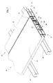
- Fig. 7 is a cut-away perspective view illustration of a fully mounted construction panel assembly in accordance with the present invention.
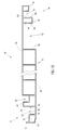
- Reference is now made to Figs. 1A, 1B and 1C, each of which illustrates a
construction panel 10 constructed and operative in accordance with a preferred embodiment of the present invention. The panel is preferably extruded of a transparent or translucent construction plastic material, such as polycarbonate and has a uniform cross sectional configuration and a desired length, which normally is greatly in excess of its width. - For the sake of clarity, it is noted that edges and all other structural features of the construction panel will be assumed to extend uniformly along the entire length of the panel and parallel to an elongate axis thereof.
- As seen in Figs. 1A, 1B and 1C,
panel 10 has afirst edge portion 12, asecond edge portion 14 and acentral body portion 16.Central body portion 16 may be of any suitable width. - Figs. 1A, 1B and 1C differ from each other in the internal configuration of the
central body portion 16. In the embodiment of Fig. 1A, the central body portion comprises a double layer of elongate enclosures having a generally rectangular cross section. In the embodiment of Fig. 1B, the central body portion comprises a single layer of elongate enclosures having a generally rectangular cross section. In the embodiment of Fig. 1C, the central body portion comprises an array of elongate enclosures having a generally triangular cross section. - The panel defines a
top surface 18 and abottom surface 20. Thetop surface 18 extends over thecentral body portion 16 and the entiresecond edge portion 14, while thebottom surface 20 extends under thecentral body portion 16 and most of the first edge portion. In the description and claims which follow, directions are referenced in the sense of Figs. 1A, 1B and 1C. - The
first edge portion 12 will now be described in detail beginning with the portion closest to thecentral body portion 16 and proceeding outwardly therefrom. Adjacent thecentral body portion 16 there is provided arecess 22 of generally square cross section and depth approximately equal to one half of the thickness of themain body portion 16. - Adjacent to and partially defining
recess 22 is a generallyrectangular protrusion 24 which extends to a height just below the level of thetop surface 18.Adjacent protrusion 24 is arecess 26 which extends down tobottom surface 20 and is bounded on one side by awall 28 ofprotrusion 24 and on an opposite side by awall 30 of aprotrusion 32. - A pair of elongate retaining
teeth surface 20, are disposed onrespective walls -
Protrusion 32 is relatively low and extends to a height just above the height ofteeth protrusion 24.Protrusion 32 has a bottom surface, part of which, indicated byreference numeral 42, is slightly raised above the level ofbottom surface 20.Protrusion 32 is bounded by an outwardupstanding wall 44 which extends upwardly to a height below that of the top surface ofprotrusion 24. - The
second edge portion 14 will now be described in detail beginning with the portion closest to thecentral body portion 16 and proceeding outwardly therefrom. It is to be appreciated that whereas the protrusions and recesses of thefirst edge portion 12 are directed upwardly in the sense of Figs. 1A, 1B and 1C, the protrusions and recesses of thesecond edge portion 14 are directed downwardly in the sense of Figs. 1A, 1B and 1C. - Adjacent the
central body portion 16 there is provided arecess 52 which extends outwardly to aninner wall 54 of aprotrusion 56.Recess 52 is bounded inwardly by anouter wall 58 of thecentral body portion 16. -
Protrusion 56 is a hollow protrusion and is outwardly bounded by awall 62 and extends downwardly to a level which lies intermediate the levels ofsurfaces surface 20. The bottommost edges ofwalls teeth surface 18.Teeth teeth adjacent panels 10 are arranged in locking engagement, as will be described hereinafter. - A
protrusion 70, of generally square cross section extends downwardly fromsurface 18 to an extend approximately half way betweensurfaces protrusion 56 by arecess 72. - Reference is now made to Figs. 2 and 3 which illustrate the structure of a
connection strip 80, which together withpanel 10 defines the construction panel assembly of the present invention. Theconnection strip 80 includes a top and abottom surface upstanding supports 86.Top surface 82 is preferably formed with anelongate notch 85. - A first edge of the
connection strip 80 is defined by anupstanding wall portion 87 which extends aboveupper top surface 82. A second edge of theconnection strip 80 is defined by anelongate hook 88 having a downward facinglip 90 and by anextension 92 ofbottom surface 84 which extends outwardly beyondhook 88 andlip 90. Theconnection strip 80 is provided withnotch 85 to ease entry ofscrews 96 thereinto, for mounting attachment of theconnection strip 80, and thus of the entire panel assembly, ontosupport structures 98. - Reference is now made to Figs. 3 - 6, which illustrate a typical sequence of steps in the assembly of a panel structure using the panel assembly of the present invention. Typically a
panel 10 is located on a plurality oftransverse support structures 98. As seen in Fig. 4, aconnection strip 80 is wedged into locking engagement withfirst edge portion 12, by pivotal motion of theconnection strip 80, in a direction indicated by anarrow 102. The result, illustrated in Fig. 5 is thathook 88 lies in intimate partially surrounding engagement withupstanding wall 44 andextension 92 underliesenclosure 32 in intimate contact withsurface 42, flush withsurface 20. - Referring now to Figs. 5 and 6, it is seen that the second edge portion of a
second panel 10 is then snap fit into engagement with theconnection strip 80 and the first edge portion of the first panel. The snap fit engagement is retained by locking engagement ofrespective tooth pair tooth pair - It may be seen from a consideration of Figs. 5 and 6 that protrusion 70 of the second edge portion is intimately seated in
recess 22 of the first edge portion andprotrusion 56 of the second edge portion is intimately seated inrecess 26 of the first edge portion and retained therein by locking engagement of the tooth pairs mentioned above. It is further seen that theconnection strip 80, as well as thescrews 96, are entirely covered and sealed from the outside environment withinrecess 52. - As seen in Fig. 7, the only seam in
surface 18 is at the outward edge ofprotrusion 70, such that any moisture entering at that seam will be collected inrecess 22 and would not reach the region ofrecess 52. - It is a particular feature of the present invention that the panel structure enables substantially unlimited longitudinal thermal expansion of the panels. This is enabled by the fact that the panels are not bolted to transverse supports.
- It is noted that connection strips 80 may be formed of any suitable material, such as plastic or aluminum. Substantially all of the stresses applied to the panels are transferred via the connection strips to structural elements of a building.
- It will be appreciated by persons skilled in the art that the present invention is not limited to that which has been particularly shown and described hereinabove. Rather the scope of the present invention is defined only by the claims which follow:
Claims (5)
- A lightweight construction panel assembly including:
a connection strip arranged to be bolted onto a support structure;
a plurality of panels arranged for mounting onto the connection strip and in generally partially overlapping side by side arrangement onto each other,
each of the plurality of panels including first and second edge portions at opposite sides of the panel,
the connection strip including a third edge portion,
the first edge portion of each panel being configured for mating engagement with the third edge portion of the connection strip and simultaneously with the second edge portion of an adjacent panel. - Apparatus according to claim 1 and wherein said second edge portion of the panel overlies the first edge portion as well as the connection strip when the assembly is fully assembled.
- A lightweight construction panel including top and bottom surfaces and first and second edge portions at opposite sides of the panel,
the first edge portion of each panel being configured for mating engagement with the second edge portion of an adjacent panel, and
the top surface extending smoothly over the second edge portion, so as to entirely cover the first edge portion when two adjacent panels are in mating engagement. - Apparatus according to any of the preceding claims and wherein said second edge portion includes a pair of spaced protrusions which are seatable into a pair of corresponding recesses defined in said first edge portion.
- Apparatus according to claim 4 and wherein one of said pair of spaced protrusions and a corresponding one of said pair of recesses are formed with interlocking teeth for retaining against disengagement.
Applications Claiming Priority (2)
| Application Number | Priority Date | Filing Date | Title |
|---|---|---|---|
| IL10564093 | 1993-05-09 | ||
| IL105640A IL105640A0 (en) | 1993-05-09 | 1993-05-09 | Lightweight construction panel assembly |
Publications (2)
| Publication Number | Publication Date |
|---|---|
| EP0624696A2 true EP0624696A2 (en) | 1994-11-17 |
| EP0624696A3 EP0624696A3 (en) | 1995-04-19 |
Family
ID=11064819
Family Applications (1)
| Application Number | Title | Priority Date | Filing Date |
|---|---|---|---|
| EP94303305A Withdrawn EP0624696A3 (en) | 1993-05-09 | 1994-05-09 | Lightweight construction panel assembly. |
Country Status (2)
| Country | Link |
|---|---|
| EP (1) | EP0624696A3 (en) |
| IL (1) | IL105640A0 (en) |
Cited By (10)
| Publication number | Priority date | Publication date | Assignee | Title |
|---|---|---|---|---|
| GB2318133A (en) * | 1996-10-11 | 1998-04-15 | Ultraframe Uk Ltd | Hollow roofing panels |
| FR2772808A1 (en) * | 1997-12-23 | 1999-06-25 | Abt | Roofing panel of recycled plastic and wood fibers |
| WO2005059268A1 (en) * | 2003-12-19 | 2005-06-30 | Erwin Steiner | Support device which is fixed to façade elements or similar on external walls of buildings |
| GB2413808A (en) * | 2004-05-07 | 2005-11-09 | Kingspan Res & Dev Ltd | Translucent roof panel |
| WO2007144861A1 (en) * | 2006-06-13 | 2007-12-21 | Kingspan Research And Developments Limited | A translucent panel |
| FR2937662A1 (en) * | 2008-10-23 | 2010-04-30 | Tdg Immo | UNIT AND ELEMENT OF HEAT EXCHANGE, CLADDING AND OCCULTATION OF A BUILDING STRUCTURE |
| US8713869B1 (en) * | 2013-03-15 | 2014-05-06 | Gordon Sales, Inc. | Suspended containment wall system |
| US9103126B2 (en) | 2011-03-18 | 2015-08-11 | Inotec Global Limited | Vertical joint system and associated surface covering system |
| AU2017201287A1 (en) * | 2017-02-24 | 2018-09-13 | Alan Brownbill | A Panel System |
| EP3581732A1 (en) * | 2018-06-15 | 2019-12-18 | Akzenta Paneele + Profile GmbH | Panel |
Citations (6)
| Publication number | Priority date | Publication date | Assignee | Title |
|---|---|---|---|---|
| AU506471B2 (en) * | 1976-06-23 | 1980-01-03 | Otto Zambelli Pty Ltd | Metal cladding |
| FR2479310A1 (en) * | 1980-03-29 | 1981-10-02 | Neumann Peter | ROOF COVER PLATE |
| EP0050462A1 (en) * | 1980-10-20 | 1982-04-28 | DAN-PAL Technical Plastic Industry for Building and Industry | Light transmitting wall panels |
| GB2147334A (en) * | 1983-09-30 | 1985-05-09 | Villadsens Fab As Jens | Building element for roof structures |
| EP0342886A1 (en) * | 1988-05-20 | 1989-11-23 | DAN-PAL Technical Plastic Industry for Building and Industry | An extruded modular panel unit |
| US5050362A (en) * | 1989-01-19 | 1991-09-24 | Polygal | Constructional panels |
-
1993
- 1993-05-09 IL IL105640A patent/IL105640A0/en unknown
-
1994
- 1994-05-09 EP EP94303305A patent/EP0624696A3/en not_active Withdrawn
Patent Citations (6)
| Publication number | Priority date | Publication date | Assignee | Title |
|---|---|---|---|---|
| AU506471B2 (en) * | 1976-06-23 | 1980-01-03 | Otto Zambelli Pty Ltd | Metal cladding |
| FR2479310A1 (en) * | 1980-03-29 | 1981-10-02 | Neumann Peter | ROOF COVER PLATE |
| EP0050462A1 (en) * | 1980-10-20 | 1982-04-28 | DAN-PAL Technical Plastic Industry for Building and Industry | Light transmitting wall panels |
| GB2147334A (en) * | 1983-09-30 | 1985-05-09 | Villadsens Fab As Jens | Building element for roof structures |
| EP0342886A1 (en) * | 1988-05-20 | 1989-11-23 | DAN-PAL Technical Plastic Industry for Building and Industry | An extruded modular panel unit |
| US5050362A (en) * | 1989-01-19 | 1991-09-24 | Polygal | Constructional panels |
Cited By (20)
| Publication number | Priority date | Publication date | Assignee | Title |
|---|---|---|---|---|
| US5901528A (en) * | 1996-10-11 | 1999-05-11 | Ultraframe Plc Of Enterprise Works | Building elements |
| GB2318133B (en) * | 1996-10-11 | 2001-03-07 | Ultraframe Uk Ltd | Building elements |
| GB2318133A (en) * | 1996-10-11 | 1998-04-15 | Ultraframe Uk Ltd | Hollow roofing panels |
| FR2772808A1 (en) * | 1997-12-23 | 1999-06-25 | Abt | Roofing panel of recycled plastic and wood fibers |
| WO2005059268A1 (en) * | 2003-12-19 | 2005-06-30 | Erwin Steiner | Support device which is fixed to façade elements or similar on external walls of buildings |
| GB2413808A (en) * | 2004-05-07 | 2005-11-09 | Kingspan Res & Dev Ltd | Translucent roof panel |
| WO2005108707A2 (en) * | 2004-05-07 | 2005-11-17 | Kingspan Research And Developments Limited | A translucent roof panel |
| WO2005108707A3 (en) * | 2004-05-07 | 2006-04-06 | Kingspan Res & Dev Ltd | A translucent roof panel |
| GB2413808B (en) * | 2004-05-07 | 2009-05-06 | Kingspan Res & Dev Ltd | A translucent roof panel |
| US8316598B2 (en) | 2006-06-13 | 2012-11-27 | Kingspan Research And Developments Limited | Translucent panel |
| WO2007144861A1 (en) * | 2006-06-13 | 2007-12-21 | Kingspan Research And Developments Limited | A translucent panel |
| GB2439190B (en) * | 2006-06-13 | 2010-09-29 | Kingspan Res & Dev Ltd | A translucent panel with multiwall support and projecting and recess portions for mating with other similar panels |
| FR2937662A1 (en) * | 2008-10-23 | 2010-04-30 | Tdg Immo | UNIT AND ELEMENT OF HEAT EXCHANGE, CLADDING AND OCCULTATION OF A BUILDING STRUCTURE |
| US9103126B2 (en) | 2011-03-18 | 2015-08-11 | Inotec Global Limited | Vertical joint system and associated surface covering system |
| US10000935B2 (en) | 2011-03-18 | 2018-06-19 | Inotec Global Limited | Vertical joint system and associated surface covering system |
| US8713869B1 (en) * | 2013-03-15 | 2014-05-06 | Gordon Sales, Inc. | Suspended containment wall system |
| AU2017201287A1 (en) * | 2017-02-24 | 2018-09-13 | Alan Brownbill | A Panel System |
| EP3581732A1 (en) * | 2018-06-15 | 2019-12-18 | Akzenta Paneele + Profile GmbH | Panel |
| WO2019238811A1 (en) * | 2018-06-15 | 2019-12-19 | Akzenta Paneele + Profile Gmbh | Panel |
| US11608646B2 (en) | 2018-06-15 | 2023-03-21 | Akzenta Paneele + Profile Gmbh | Panel |
Also Published As
| Publication number | Publication date |
|---|---|
| IL105640A0 (en) | 1993-09-22 |
| EP0624696A3 (en) | 1995-04-19 |
Similar Documents
| Publication | Publication Date | Title |
|---|---|---|
| US6182405B1 (en) | Window frame structure | |
| US5105593A (en) | Weatherproof curtain wall unit | |
| EP0624696A2 (en) | Lightweight construction panel assembly | |
| GB2147334A (en) | Building element for roof structures | |
| GB2197015A (en) | Plastic clad timber frames | |
| GB2351095A (en) | Hollow plastic building element | |
| US20040244309A1 (en) | Modular construction system | |
| GB2275064A (en) | Roofridge for e.g. a conservatory | |
| JPH0835272A (en) | Partition panel device | |
| JP2000064476A (en) | External wall | |
| JP2538539B2 (en) | How to attach the sliding shoji | |
| JPS6035749Y2 (en) | fittings | |
| JP3044171B2 (en) | Gate | |
| JP2859813B2 (en) | Joint structure of wall panel in partition | |
| CA2292125C (en) | Window frame structure | |
| JP2811478B2 (en) | Seismic ventilation building tile structure | |
| EP0872605A2 (en) | Insulating construction element | |
| JP2555630Y2 (en) | Jointer Joiner | |
| JPH0481018B2 (en) | ||
| JPH09189094A (en) | Partitioning panel and its shelf plate supporting member locking structure | |
| JPH044081Y2 (en) | ||
| KR200265937Y1 (en) | outer panel for wood house wall | |
| JP2758842B2 (en) | Drainer mounting structure | |
| JP2500014Y2 (en) | Exterior panel mounting structure | |
| JPH0240173Y2 (en) |
Legal Events
| Date | Code | Title | Description |
|---|---|---|---|
| PUAI | Public reference made under article 153(3) epc to a published international application that has entered the european phase |
Free format text: ORIGINAL CODE: 0009012 |
|
| AK | Designated contracting states |
Kind code of ref document: A2 Designated state(s): AT BE CH DE DK ES FR GB GR IE IT LI LU MC NL PT SE |
|
| PUAL | Search report despatched |
Free format text: ORIGINAL CODE: 0009013 |
|
| AK | Designated contracting states |
Kind code of ref document: A3 Designated state(s): AT BE CH DE DK ES FR GB GR IE IT LI LU MC NL PT SE |
|
| STAA | Information on the status of an ep patent application or granted ep patent |
Free format text: STATUS: THE APPLICATION IS DEEMED TO BE WITHDRAWN |
|
| 18D | Application deemed to be withdrawn |
Effective date: 19951020 |