EP0622958B1 - Real-time data transmitter and receiver - Google Patents
Real-time data transmitter and receiver Download PDFInfo
- Publication number
- EP0622958B1 EP0622958B1 EP94106493A EP94106493A EP0622958B1 EP 0622958 B1 EP0622958 B1 EP 0622958B1 EP 94106493 A EP94106493 A EP 94106493A EP 94106493 A EP94106493 A EP 94106493A EP 0622958 B1 EP0622958 B1 EP 0622958B1
- Authority
- EP
- European Patent Office
- Prior art keywords
- data
- frame count
- frame
- motion image
- real
- Prior art date
- Legal status (The legal status is an assumption and is not a legal conclusion. Google has not performed a legal analysis and makes no representation as to the accuracy of the status listed.)
- Expired - Lifetime
Links
Images

Classifications
-
- H—ELECTRICITY
- H04—ELECTRIC COMMUNICATION TECHNIQUE
- H04N—PICTORIAL COMMUNICATION, e.g. TELEVISION
- H04N7/00—Television systems
- H04N7/12—Systems in which the television signal is transmitted via one channel or a plurality of parallel channels, the bandwidth of each channel being less than the bandwidth of the television signal
-
- H—ELECTRICITY
- H04—ELECTRIC COMMUNICATION TECHNIQUE
- H04N—PICTORIAL COMMUNICATION, e.g. TELEVISION
- H04N21/00—Selective content distribution, e.g. interactive television or video on demand [VOD]
- H04N21/40—Client devices specifically adapted for the reception of or interaction with content, e.g. set-top-box [STB]; Operations thereof
- H04N21/43—Processing of content or additional data, e.g. demultiplexing additional data from a digital video stream; Elementary client operations, e.g. monitoring of home network or synchronising decoder's clock; Client middleware
- H04N21/4302—Content synchronisation processes, e.g. decoder synchronisation
-
- H—ELECTRICITY
- H04—ELECTRIC COMMUNICATION TECHNIQUE
- H04N—PICTORIAL COMMUNICATION, e.g. TELEVISION
- H04N21/00—Selective content distribution, e.g. interactive television or video on demand [VOD]
- H04N21/20—Servers specifically adapted for the distribution of content, e.g. VOD servers; Operations thereof
- H04N21/23—Processing of content or additional data; Elementary server operations; Server middleware
- H04N21/242—Synchronization processes, e.g. processing of PCR [Program Clock References]
-
- H—ELECTRICITY
- H04—ELECTRIC COMMUNICATION TECHNIQUE
- H04N—PICTORIAL COMMUNICATION, e.g. TELEVISION
- H04N21/00—Selective content distribution, e.g. interactive television or video on demand [VOD]
- H04N21/60—Network structure or processes for video distribution between server and client or between remote clients; Control signalling between clients, server and network components; Transmission of management data between server and client, e.g. sending from server to client commands for recording incoming content stream; Communication details between server and client
- H04N21/63—Control signaling related to video distribution between client, server and network components; Network processes for video distribution between server and clients or between remote clients, e.g. transmitting basic layer and enhancement layers over different transmission paths, setting up a peer-to-peer communication via Internet between remote STB's; Communication protocols; Addressing
- H04N21/643—Communication protocols
- H04N21/6437—Real-time Transport Protocol [RTP]
-
- H—ELECTRICITY
- H04—ELECTRIC COMMUNICATION TECHNIQUE
- H04N—PICTORIAL COMMUNICATION, e.g. TELEVISION
- H04N7/00—Television systems
- H04N7/24—Systems for the transmission of television signals using pulse code modulation
- H04N7/52—Systems for transmission of a pulse code modulated video signal with one or more other pulse code modulated signals, e.g. an audio signal or a synchronizing signal
- H04N7/54—Systems for transmission of a pulse code modulated video signal with one or more other pulse code modulated signals, e.g. an audio signal or a synchronizing signal the signals being synchronous
- H04N7/56—Synchronising systems therefor
Landscapes
- Engineering & Computer Science (AREA)
- Multimedia (AREA)
- Signal Processing (AREA)
- Time-Division Multiplex Systems (AREA)
- Television Systems (AREA)
- Small-Scale Networks (AREA)
- Synchronisation In Digital Transmission Systems (AREA)
- Compression Or Coding Systems Of Tv Signals (AREA)
Description
30 x 215 or 11110 000000000000000B (525/60)
36 x 215 or 100100 000000000000000B (625/50)
Claims (9)
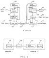
- A real-time data transmitter apparatus for transmitting digital motion image data (202;303;402) through a digital transmission channel (206;308;407)in the form of a stream of bits transmitted in synchronisation with a transmission clock signal generated by a clock generator (203;304;403), the digital motion image data being accompanied with a frame pulse (201;301;401) occurring at intervals of a frame of a motion image, characterized by:a clock counter (204;305;404) responsive to the frame pulse for counting clocks of the transmission clock signal during each of said intervals to produce a frame count which indicates a start time of the frame of the motion image; anda data mixer (205;307;406) receiving the digital motion image data and coupled to the clock counter for merging a frame count information based on said frame count with the digital motion image data to produce composite data, the composite data being transmitted through the digital transmission channel (206;308;407).
- A real-time data transmitter apparatus according to claim 1 further comprising:
a difference generator (306) for generating a difference as said frame count information between the frame count and a reference (302) attributed to the data transmitter apparatus. - A real-time data transmitter apparatus according to claim 1 further comprising:
a lower-bit generator (405) for separating a specific number of lower bits as said frame count information from the frame count produced by the clock counter (404). - A real-time data transmitter apparatus according to one of the claims 1-3, wherein the frame count, the difference, or the lower bits are respectively reduced in accuracy before being transmitted.
- A real-time data transmitter apparatus according to one of the claims 1-4, wherein if the transmission clock signal is 30 x n MHz, where n is an integer, a reference for the frame period is expressed as 30 x 215 x n for a 525/60, 1125/60 or 1050/60 TV signal format and 36 x 215 x n for a 625/50 or 1250/50 TV signal format.
- A real-time data receiver apparatus for receiving from a digital transmission channel (206;308;407) composite data in the form of a stream of bits which comprise digital motion image data and a frame count information, for outputting the digital motion image data (211;315;414) and the frame count (210;313;412) which indicates a start time of a frame of a motion image, said apparatus having a clock reproducer (207;309;408) for reproducing the transmission clock signal from the received composite data, the frame count being a counting result of the clock pulses, characterized by:a data separator (209;312;411) for separating the frame count information from the composite data; anda clock counter (208;310;409) coupled to the clock reproducer (207;309;408) and the data separator (209;312;411) for counting clocks of the reproduced transmission clock signal and outputting the frame pulse every time when the count result becomes equal to the value indicated by the frame count.
- A real-time data receiver apparatus according to claim 6, wherein the frame count information separated from the received composite data by said separator (312) is a difference between a frame count and a reference, further comprising:
a frame count reproducer means (311) for reproducing the frame count by adding the difference with a reference (314). - A real-time data receiver apparatus according to claim 6, wherein the frame count information separated from the received composite data by said separator (411) are lower bits, further comprising:
a frame count reproducer (410) for reproducing the frame count from the lower bits. - A real-time data receiver apparatus according to claim 8, characterized in that
the frame count reproducer (410) is reproducing the frame count by merging the lower bits with upper bits of a reference (413) which comprises a product of an integer and a power of 2.
Applications Claiming Priority (2)
| Application Number | Priority Date | Filing Date | Title |
|---|---|---|---|
| JP102363/93 | 1993-04-28 | ||
| JP10236393 | 1993-04-28 |
Publications (3)
| Publication Number | Publication Date |
|---|---|
| EP0622958A2 EP0622958A2 (en) | 1994-11-02 |
| EP0622958A3 EP0622958A3 (en) | 1995-03-15 |
| EP0622958B1 true EP0622958B1 (en) | 1998-08-12 |
Family
ID=14325382
Family Applications (1)
| Application Number | Title | Priority Date | Filing Date |
|---|---|---|---|
| EP94106493A Expired - Lifetime EP0622958B1 (en) | 1993-04-28 | 1994-04-26 | Real-time data transmitter and receiver |
Country Status (5)
| Country | Link |
|---|---|
| US (1) | US5574752A (en) |
| EP (1) | EP0622958B1 (en) |
| JP (1) | JP2000341234A (en) |
| KR (1) | KR0151569B1 (en) |
| DE (1) | DE69412337T2 (en) |
Families Citing this family (13)
| Publication number | Priority date | Publication date | Assignee | Title |
|---|---|---|---|---|
| US6008858A (en) * | 1996-12-06 | 1999-12-28 | Ati Technologies, Inc | Video timing generation |
| US6040871A (en) * | 1996-12-27 | 2000-03-21 | Lucent Technologies Inc. | Method and apparatus for synchronizing video signals |
| KR100221336B1 (en) * | 1996-12-28 | 1999-09-15 | 전주범 | Frame harmonic apparatus and method of multi-receiver system |
| JPH1174878A (en) * | 1997-08-28 | 1999-03-16 | Mitsubishi Electric Corp | Digital data transmission system |
| EP1408693A1 (en) * | 1998-04-07 | 2004-04-14 | Matsushita Electric Industrial Co., Ltd. | On-vehicle image display apparatus, image transmission system, image transmission apparatus, and image capture apparatus |
| JPH11331248A (en) * | 1998-05-08 | 1999-11-30 | Sony Corp | Transmitter, transmission method, receiver, reception method and provision medium |
| JP2000184351A (en) * | 1998-12-11 | 2000-06-30 | Office Noa:Kk | Moving picture distribution method and its system |
| US20010055354A1 (en) * | 2000-03-03 | 2001-12-27 | Danny Fung | Method & apparatus for data rate synchronization |
| JP4564350B2 (en) * | 2004-12-27 | 2010-10-20 | 株式会社東芝 | Signal processing device |
| JP2006270792A (en) * | 2005-03-25 | 2006-10-05 | Fujitsu Ltd | Frame transmission method and device |
| EP2045937B1 (en) * | 2007-10-04 | 2019-06-19 | Microchip Technology Germany GmbH | System and method for real time synchronization through a communication system |
| WO2010037916A1 (en) * | 2008-10-03 | 2010-04-08 | Thomson Licensing | Equipment synchronization independent of the standard of the synchronization signal |
| JP5802727B2 (en) * | 2013-11-11 | 2015-10-28 | 東芝テリー株式会社 | Synchronous camera |
Family Cites Families (12)
| Publication number | Priority date | Publication date | Assignee | Title |
|---|---|---|---|---|
| CA1294701C (en) * | 1907-08-20 | 1992-01-21 | Norio Suzuki | Color television signal sampling clock phase control system |
| US4066964A (en) * | 1967-01-06 | 1978-01-03 | Rockwell International Corporation | Communication system |
| US3795763A (en) * | 1972-04-18 | 1974-03-05 | Communications Satellite Corp | Digital television transmission system |
| US4353090A (en) * | 1979-06-20 | 1982-10-05 | Discovision Associates | Extended play video recording and reproducing system with selection of multiplexed audio |
| JPS60212049A (en) * | 1984-04-06 | 1985-10-24 | Nec Corp | Frame synchronization system |
| US4631586A (en) * | 1984-06-04 | 1986-12-23 | United States Of America As Represented By The Secretary Of The Navy | Digital raster timing encoder/decoder |
| US4759040A (en) * | 1986-02-01 | 1988-07-19 | Iwatsu Electric Co., Ltd. | Digital synchronizing circuit |
| JPH0783337B2 (en) * | 1988-03-01 | 1995-09-06 | 日本電気株式会社 | Scramble-descramble method |
| US5124985A (en) * | 1988-12-13 | 1992-06-23 | Small Power Communication Systems Research Laboratories Co., Ltd. | Radiocommunication system using time-division digital frames |
| GB2240231B (en) * | 1990-01-19 | 1994-03-30 | British Broadcasting Corp | High definition television coder/decoder |
| JP2937529B2 (en) * | 1991-03-27 | 1999-08-23 | 日本電気株式会社 | Clock recovery circuit |
| US5260978A (en) * | 1992-10-30 | 1993-11-09 | Bell Communications Research, Inc. | Synchronous residual time stamp for timing recovery in a broadband network |
-
1994
- 1994-04-26 DE DE69412337T patent/DE69412337T2/en not_active Expired - Fee Related
- 1994-04-26 EP EP94106493A patent/EP0622958B1/en not_active Expired - Lifetime
- 1994-04-27 KR KR1019940008917A patent/KR0151569B1/en not_active IP Right Cessation
-
1995
- 1995-08-04 US US08/511,320 patent/US5574752A/en not_active Expired - Fee Related
-
2000
- 2000-04-28 JP JP2000129149A patent/JP2000341234A/en active Pending
Also Published As
| Publication number | Publication date |
|---|---|
| DE69412337T2 (en) | 1998-12-10 |
| JP2000341234A (en) | 2000-12-08 |
| EP0622958A2 (en) | 1994-11-02 |
| US5574752A (en) | 1996-11-12 |
| KR0151569B1 (en) | 1998-10-15 |
| KR940025343A (en) | 1994-11-19 |
| EP0622958A3 (en) | 1995-03-15 |
| DE69412337D1 (en) | 1998-09-17 |
Similar Documents
| Publication | Publication Date | Title |
|---|---|---|
| RU2117411C1 (en) | Device for video signal compression and synchronization device | |
| US4689661A (en) | Method of simultaneously transmitting a plurality of television signals on a single radio link and apparatus adapted to carry out said method | |
| EP0622958B1 (en) | Real-time data transmitter and receiver | |
| US6069902A (en) | Broadcast receiver, transmission control unit and recording/reproducing apparatus | |
| US4396947A (en) | Apparatus for encoding of information | |
| DE69814725T2 (en) | Method and device for recording differently formatted compressed audio and video data | |
| US5568403A (en) | Audio/video/data component system bus | |
| US5907827A (en) | Channel synchronized audio data compression and decompression for an in-flight entertainment system | |
| US4646147A (en) | Method and apparatus for scrambling and unscrambling television signals | |
| EP0771110A3 (en) | Digital video playback apparatus for special reproduction mode | |
| EP0152309A2 (en) | Television sound signal processing apparatus | |
| US4982270A (en) | Video data transmitting system | |
| KR19990021831A (en) | Data multiplexer and its method | |
| JPH11317768A (en) | Transmission system, transmitting device, recording and reproducing device, and recording device | |
| CA1232058A (en) | System for coding video signal in block units | |
| RU96111973A (en) | METHOD AND DEVICE FOR TRANSMISSION OF ADDITIONAL SIGNALS ON TELEVISION CHANNELS AND APPLICATION OF A METHOD FOR TRANSMISSION OF INFORMATION | |
| US4589109A (en) | Multiplexed digital data transmission | |
| JPH0787124A (en) | Data multiplex device and separator | |
| JPH0795194A (en) | Data transmitter and data receiver | |
| JP2558730B2 (en) | Video transmission system | |
| Reynolds et al. | Multiplexing and demultiplexing digital audio and video in today's digital environment | |
| GB2042846A (en) | Secret television | |
| JP2676805B2 (en) | Sampling clock phase control system | |
| JP2605435B2 (en) | PCM transmission device, PCM reception device, digital audio interface format data transmission device, and digital audio interface format data reception device | |
| KR100199960B1 (en) | Apparatus for generating and reproducing sync. clock |
Legal Events
| Date | Code | Title | Description |
|---|---|---|---|
| PUAI | Public reference made under article 153(3) epc to a published international application that has entered the european phase |
Free format text: ORIGINAL CODE: 0009012 |
|
| AK | Designated contracting states |
Kind code of ref document: A2 Designated state(s): DE FR GB NL |
|
| PUAL | Search report despatched |
Free format text: ORIGINAL CODE: 0009013 |
|
| AK | Designated contracting states |
Kind code of ref document: A3 Designated state(s): DE FR GB NL |
|
| 17P | Request for examination filed |
Effective date: 19950523 |
|
| 17Q | First examination report despatched |
Effective date: 19950713 |
|
| GRAG | Despatch of communication of intention to grant |
Free format text: ORIGINAL CODE: EPIDOS AGRA |
|
| GRAG | Despatch of communication of intention to grant |
Free format text: ORIGINAL CODE: EPIDOS AGRA |
|
| GRAH | Despatch of communication of intention to grant a patent |
Free format text: ORIGINAL CODE: EPIDOS IGRA |
|
| GRAH | Despatch of communication of intention to grant a patent |
Free format text: ORIGINAL CODE: EPIDOS IGRA |
|
| GRAA | (expected) grant |
Free format text: ORIGINAL CODE: 0009210 |
|
| AK | Designated contracting states |
Kind code of ref document: B1 Designated state(s): DE FR GB NL |
|
| REF | Corresponds to: |
Ref document number: 69412337 Country of ref document: DE Date of ref document: 19980917 |
|
| ET | Fr: translation filed | ||
| PLBE | No opposition filed within time limit |
Free format text: ORIGINAL CODE: 0009261 |
|
| STAA | Information on the status of an ep patent application or granted ep patent |
Free format text: STATUS: NO OPPOSITION FILED WITHIN TIME LIMIT |
|
| 26N | No opposition filed | ||
| REG | Reference to a national code |
Ref country code: GB Ref legal event code: IF02 |
|
| PGFP | Annual fee paid to national office [announced via postgrant information from national office to epo] |
Ref country code: NL Payment date: 20070415 Year of fee payment: 14 |
|
| PGFP | Annual fee paid to national office [announced via postgrant information from national office to epo] |
Ref country code: DE Payment date: 20070419 Year of fee payment: 14 |
|
| PGFP | Annual fee paid to national office [announced via postgrant information from national office to epo] |
Ref country code: GB Payment date: 20070425 Year of fee payment: 14 |
|
| PGFP | Annual fee paid to national office [announced via postgrant information from national office to epo] |
Ref country code: FR Payment date: 20070411 Year of fee payment: 14 |
|
| GBPC | Gb: european patent ceased through non-payment of renewal fee |
Effective date: 20080426 |
|
| NLV4 | Nl: lapsed or anulled due to non-payment of the annual fee |
Effective date: 20081101 |
|
| PG25 | Lapsed in a contracting state [announced via postgrant information from national office to epo] |
Ref country code: NL Free format text: LAPSE BECAUSE OF NON-PAYMENT OF DUE FEES Effective date: 20081101 Ref country code: DE Free format text: LAPSE BECAUSE OF NON-PAYMENT OF DUE FEES Effective date: 20081101 |
|
| REG | Reference to a national code |
Ref country code: FR Ref legal event code: ST Effective date: 20081231 |
|
| PG25 | Lapsed in a contracting state [announced via postgrant information from national office to epo] |
Ref country code: FR Free format text: LAPSE BECAUSE OF NON-PAYMENT OF DUE FEES Effective date: 20080430 |
|
| PG25 | Lapsed in a contracting state [announced via postgrant information from national office to epo] |
Ref country code: GB Free format text: LAPSE BECAUSE OF NON-PAYMENT OF DUE FEES Effective date: 20080426 |