EP0622527B1 - An adjustable force transmission arrangement for a camshaft of a large diesel engine - Google Patents
An adjustable force transmission arrangement for a camshaft of a large diesel engine Download PDFInfo
- Publication number
- EP0622527B1 EP0622527B1 EP94301037A EP94301037A EP0622527B1 EP 0622527 B1 EP0622527 B1 EP 0622527B1 EP 94301037 A EP94301037 A EP 94301037A EP 94301037 A EP94301037 A EP 94301037A EP 0622527 B1 EP0622527 B1 EP 0622527B1
- Authority
- EP
- European Patent Office
- Prior art keywords
- gear wheel
- guiding element
- force transmission
- engine
- transmission arrangement
- Prior art date
- Legal status (The legal status is an assumption and is not a legal conclusion. Google has not performed a legal analysis and makes no representation as to the accuracy of the status listed.)
- Expired - Lifetime
Links
- 230000005540 biological transmission Effects 0.000 title claims abstract description 20
- 230000005611 electricity Effects 0.000 description 1
- 239000012530 fluid Substances 0.000 description 1
- 238000000034 method Methods 0.000 description 1
- 238000012986 modification Methods 0.000 description 1
- 230000004048 modification Effects 0.000 description 1
- 238000010248 power generation Methods 0.000 description 1
Images
Classifications
-
- F—MECHANICAL ENGINEERING; LIGHTING; HEATING; WEAPONS; BLASTING
- F01—MACHINES OR ENGINES IN GENERAL; ENGINE PLANTS IN GENERAL; STEAM ENGINES
- F01L—CYCLICALLY OPERATING VALVES FOR MACHINES OR ENGINES
- F01L1/00—Valve-gear or valve arrangements, e.g. lift-valve gear
- F01L1/02—Valve drive
- F01L1/026—Gear drive
-
- F—MECHANICAL ENGINEERING; LIGHTING; HEATING; WEAPONS; BLASTING
- F01—MACHINES OR ENGINES IN GENERAL; ENGINE PLANTS IN GENERAL; STEAM ENGINES
- F01L—CYCLICALLY OPERATING VALVES FOR MACHINES OR ENGINES
- F01L1/00—Valve-gear or valve arrangements, e.g. lift-valve gear
- F01L1/02—Valve drive
-
- F—MECHANICAL ENGINEERING; LIGHTING; HEATING; WEAPONS; BLASTING
- F01—MACHINES OR ENGINES IN GENERAL; ENGINE PLANTS IN GENERAL; STEAM ENGINES
- F01L—CYCLICALLY OPERATING VALVES FOR MACHINES OR ENGINES
- F01L1/00—Valve-gear or valve arrangements, e.g. lift-valve gear
- F01L1/34—Valve-gear or valve arrangements, e.g. lift-valve gear characterised by the provision of means for changing the timing of the valves without changing the duration of opening and without affecting the magnitude of the valve lift
- F01L1/344—Valve-gear or valve arrangements, e.g. lift-valve gear characterised by the provision of means for changing the timing of the valves without changing the duration of opening and without affecting the magnitude of the valve lift changing the angular relationship between crankshaft and camshaft, e.g. using helicoidal gear
-
- F—MECHANICAL ENGINEERING; LIGHTING; HEATING; WEAPONS; BLASTING
- F16—ENGINEERING ELEMENTS AND UNITS; GENERAL MEASURES FOR PRODUCING AND MAINTAINING EFFECTIVE FUNCTIONING OF MACHINES OR INSTALLATIONS; THERMAL INSULATION IN GENERAL
- F16D—COUPLINGS FOR TRANSMITTING ROTATION; CLUTCHES; BRAKES
- F16D1/00—Couplings for rigidly connecting two coaxial shafts or other movable machine elements
- F16D1/06—Couplings for rigidly connecting two coaxial shafts or other movable machine elements for attachment of a member on a shaft or on a shaft-end
- F16D1/076—Couplings for rigidly connecting two coaxial shafts or other movable machine elements for attachment of a member on a shaft or on a shaft-end by clamping together two faces perpendicular to the axis of rotation, e.g. with bolted flanges
-
- F—MECHANICAL ENGINEERING; LIGHTING; HEATING; WEAPONS; BLASTING
- F02—COMBUSTION ENGINES; HOT-GAS OR COMBUSTION-PRODUCT ENGINE PLANTS
- F02B—INTERNAL-COMBUSTION PISTON ENGINES; COMBUSTION ENGINES IN GENERAL
- F02B3/00—Engines characterised by air compression and subsequent fuel addition
- F02B3/06—Engines characterised by air compression and subsequent fuel addition with compression ignition
-
- Y—GENERAL TAGGING OF NEW TECHNOLOGICAL DEVELOPMENTS; GENERAL TAGGING OF CROSS-SECTIONAL TECHNOLOGIES SPANNING OVER SEVERAL SECTIONS OF THE IPC; TECHNICAL SUBJECTS COVERED BY FORMER USPC CROSS-REFERENCE ART COLLECTIONS [XRACs] AND DIGESTS
- Y10—TECHNICAL SUBJECTS COVERED BY FORMER USPC
- Y10T—TECHNICAL SUBJECTS COVERED BY FORMER US CLASSIFICATION
- Y10T74/00—Machine element or mechanism
- Y10T74/19—Gearing
- Y10T74/1956—Adjustable
-
- Y—GENERAL TAGGING OF NEW TECHNOLOGICAL DEVELOPMENTS; GENERAL TAGGING OF CROSS-SECTIONAL TECHNOLOGIES SPANNING OVER SEVERAL SECTIONS OF THE IPC; TECHNICAL SUBJECTS COVERED BY FORMER USPC CROSS-REFERENCE ART COLLECTIONS [XRACs] AND DIGESTS
- Y10—TECHNICAL SUBJECTS COVERED BY FORMER USPC
- Y10T—TECHNICAL SUBJECTS COVERED BY FORMER US CLASSIFICATION
- Y10T74/00—Machine element or mechanism
- Y10T74/21—Elements
- Y10T74/2101—Cams
- Y10T74/2102—Adjustable
Definitions
- the invention relates to an adjustable force transmission arrangement in a large diesel engine for accomplishing force transmission from a crankshaft of the engine by means of gear wheels to at least one camshaft of the engine in accordance with the preamble of claim 1.
- a large diesel engine as referred to herein means an engine usable for example as the main propulsion engine or as an auxiliary engine for a ship or for power generation in the form of heat and/or electricity in a power plant.
- EP-A-280774 discloses an adjustable force transmission arrangement including a guiding element fixed to the engine block and to which gear wheels needed for the force transmission are turnably supported. The adjustment is carried out so that the gear wheel fixed to the camshaft is temporarily released by utilizing a hydraulic fluid to thereby allow turning of the camshaft relative to the gear wheel and, thus, to the crankshaft. Therefore the arrangement is complicated and the adjustment operation time consuming.
- a force transmission arrangement relying on friction between the gear wheels would make it possible to accommodate large angular adjustments but for it to be a practical solution it would be necessary to ensure that the measures needed for accomplishing an adjustment are as simple as possible.
- one aim of the invention is to provide a force transmission arrangement relying on friction between two gear wheels which is constructionally uncomplicated and reliable. Also the mutual attachment and detachment of the gear wheels as well as the adjustment of the relative positions thereof should be accomplished as simply as possible.
- the arrangement according to the invention is characterised in that the guiding element is supported by means of at least one bearing element to the engine block and in that the guiding element is arranged to be fixed to the first gear wheel by means of at least one screwed member so that the second gear wheel is clamped between the first gear wheel and the guiding element and receives from these pieces its location also in the radial direction.
- the guiding element itself is turnably journalled to the engine block and has its location set both in the radial direction and in the axial direction, a force transmission arrangement according to this invention is uncomplicated and reliable.
- the at least one bearing element provides a first bearing surface extending in the axial direction with regard to the first and second gear wheels and a second bearing surface substantially perpendicular to said first bearing surface, the guiding element being provided with a flange member extending in the radial direction which is arranged to cooperate with said second bearing surface for setting the location of said gear wheels in the axial direction thereof relative to the engine block.
- the arrangement includes a second bearing element arranged between the engine block and the second gear wheel which acts to confirm the location of the guiding element in the radial direction and in addition to set the location of the second gear wheel in the axial direction.
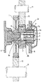
- gear wheel 1 indicates a gear wheel, which is drivably connected to a crankshaft 9 of a large diesel engine by means of a gear wheel 10.
- gear wheel 2 is drivably connected to a camshaft 11 of the same engine by means of a gear wheel 12.
- the force transmission arrangement and the shafts are shown only schematically and in chain lines.
- the force transmission arrangement can additionally include for instance one or more intermediate gear wheels should such be required.
- the gear wheel 1 is mounted in bearings to one part of the block 6 of the engine.
- a guiding element 3 is also mounted to the engine block 6 by means of a pair of annular bearing bushes 7 and 8 with a small clearance 13 therebetween. Location of the guiding element 3 in the radial direction is set by means of bearing surfaces 7a and 8a on the bushes 7 and 8, respectively.
- the guiding element 3 includes a flange member 3a, which sets its location in the axial direction through a bearing surface 7b of the bush 7, which surface 7b is perpendicular to the surface 7a thereof.
- the guiding element 3 is secured to the gear wheel 1 by means of screw bolts 4 so that the gear wheel 2 is clamped between the gear wheel 1 and the guiding element 3.
- Force transmission from the gear wheel 1 to the gear wheel 2 then occurs through friction at surfaces 5 formed (as shown) by confronting faces of the wheels 1 and 2.
- the arrangement does not require any separate shaft, since the gear wheel 2 is mounted on (and thus is set in the radial direction by) spigot parts 1b, 3b of the gear wheel 1 and the guiding element 3, respectively.
- the angular position of one of the gear wheels 1 and 2 with respect to the other can be changed by loosening the screw bolts 4, to reduce the frictional drag created at the friction surfaces 5 to the point where it allows turning of one gear wheel relative to the other.
- any turning of the screw bolts 4 can be carried out from one end of the entire arrangement (i.e. the right-hand end as shown), loosening, adjustment and retightening operations can easily be accomplished.
- the number of the screw bolts 4 is not decisive. The main thing is that a sufficiently large and uniform load is exerted over the friction surfaces 5 to securely lock the gear wheels 1, 2 together in any adjusted position.
- just one screw bolt positioned axially in the centre of element 3 and gear wheel 1 can be enough to provide a sufficient tightening force to secure the set adjustment between the gear wheels 1 and 2.
- the bearing elements 7, 8 need not be annular bushes as shown provided they provide the required radial and axial positioning for the force transmission arrangement.
Landscapes
- Engineering & Computer Science (AREA)
- General Engineering & Computer Science (AREA)
- Mechanical Engineering (AREA)
- Gear Transmission (AREA)
- Valve-Gear Or Valve Arrangements (AREA)
- Gears, Cams (AREA)
- Valve Device For Special Equipments (AREA)
Abstract
Description
- The invention relates to an adjustable force transmission arrangement in a large diesel engine for accomplishing force transmission from a crankshaft of the engine by means of gear wheels to at least one camshaft of the engine in accordance with the preamble of claim 1.
- A large diesel engine as referred to herein means an engine usable for example as the main propulsion engine or as an auxiliary engine for a ship or for power generation in the form of heat and/or electricity in a power plant.
- Force transmission arrangements for an engine camshaft are known, in which adjoining gear wheels are directly fixed to each other by means of screw bolts for example. In this case the setting of the rotational angle of the camshaft relative to the crankshaft can be changed by adjusting the relative positions of the gear wheels. For this purpose the holes provided for the screw bolts have to be oval so that the position of the screw bolts in the tangential direction of the gear wheels can be adjusted. This solution, however, allows for only a relatively small adjustment to be made and in addition it is a laborious procedure to make an adjustment.
- EP-A-280774 discloses an adjustable force transmission arrangement including a guiding element fixed to the engine block and to which gear wheels needed for the force transmission are turnably supported. The adjustment is carried out so that the gear wheel fixed to the camshaft is temporarily released by utilizing a hydraulic fluid to thereby allow turning of the camshaft relative to the gear wheel and, thus, to the crankshaft. Therefore the arrangement is complicated and the adjustment operation time consuming.
- A force transmission arrangement relying on friction between the gear wheels, known as such, would make it possible to accommodate large angular adjustments but for it to be a practical solution it would be necessary to ensure that the measures needed for accomplishing an adjustment are as simple as possible. Thus, one aim of the invention is to provide a force transmission arrangement relying on friction between two gear wheels which is constructionally uncomplicated and reliable. Also the mutual attachment and detachment of the gear wheels as well as the adjustment of the relative positions thereof should be accomplished as simply as possible.
- The aims of the invention are accomplished in a way more clearly defined in claim 1 and in the other claims. The arrangement according to the invention is characterised in that the guiding element is supported by means of at least one bearing element to the engine block and in that the guiding element is arranged to be fixed to the first gear wheel by means of at least one screwed member so that the second gear wheel is clamped between the first gear wheel and the guiding element and receives from these pieces its location also in the radial direction. Thus, as the guiding element itself is turnably journalled to the engine block and has its location set both in the radial direction and in the axial direction, a force transmission arrangement according to this invention is uncomplicated and reliable. At the same time loosening and tightening of the gear wheels one to the other can take place In a simple way by means of said at least one screwed member from one end of the whole arrangement. Due to the frictional drive used between the gear wheels a large range of angular adjustment therebetween is possible.
- Desirably the at least one bearing element provides a first bearing surface extending in the axial direction with regard to the first and second gear wheels and a second bearing surface substantially perpendicular to said first bearing surface, the guiding element being provided with a flange member extending in the radial direction which is arranged to cooperate with said second bearing surface for setting the location of said gear wheels in the axial direction thereof relative to the engine block.
- Conveniently the arrangement includes a second bearing element arranged between the engine block and the second gear wheel which acts to confirm the location of the guiding element in the radial direction and in addition to set the location of the second gear wheel in the axial direction.
- The invention will now be further described, by way of example, with reference to the accompanying drawing, the sole figure of which represents an arrangement according to the invention, shown in axial section.
- In the drawing 1 indicates a gear wheel, which is drivably connected to a crankshaft 9 of a large diesel engine by means of a
gear wheel 10. Correspondingly, agear wheel 2 is drivably connected to acamshaft 11 of the same engine by means of agear wheel 12. With the exception of thegear wheels 1 and 2, the force transmission arrangements and the shafts are shown only schematically and in chain lines. Thus, in practice the force transmission arrangement can additionally include for instance one or more intermediate gear wheels should such be required. - The gear wheel 1 is mounted in bearings to one part of the
block 6 of the engine. In addition a guiding element 3 is also mounted to theengine block 6 by means of a pair ofannular bearing bushes 7 and 8 with asmall clearance 13 therebetween. Location of the guiding element 3 in the radial direction is set by means of bearing surfaces 7a and 8a on thebushes 7 and 8, respectively. In addition, the guiding element 3 includes a flange member 3a, which sets its location in the axial direction through abearing surface 7b of the bush 7, whichsurface 7b is perpendicular to the surface 7a thereof. - The guiding element 3 is secured to the gear wheel 1 by means of
screw bolts 4 so that thegear wheel 2 is clamped between the gear wheel 1 and the guiding element 3. Force transmission from the gear wheel 1 to thegear wheel 2 then occurs through friction at surfaces 5 formed (as shown) by confronting faces of thewheels 1 and 2. A bearing surface 8b of thebush 8, which is perpendicular to the surface 8a thereof, confirms the location of thegear wheel 2 axially with respect to the element 3. The arrangement does not require any separate shaft, since thegear wheel 2 is mounted on (and thus is set in the radial direction by)spigot parts - The angular position of one of the
gear wheels 1 and 2 with respect to the other (and thus the setting of the timing of the camshaft 11) can be changed by loosening thescrew bolts 4, to reduce the frictional drag created at the friction surfaces 5 to the point where it allows turning of one gear wheel relative to the other. As any turning of thescrew bolts 4 can be carried out from one end of the entire arrangement (i.e. the right-hand end as shown), loosening, adjustment and retightening operations can easily be accomplished. - The number of the
screw bolts 4 is not decisive. The main thing is that a sufficiently large and uniform load is exerted over the friction surfaces 5 to securely lock thegear wheels 1, 2 together in any adjusted position. Thus, in principle, just one screw bolt positioned axially in the centre of element 3 and gear wheel 1 can be enough to provide a sufficient tightening force to secure the set adjustment between thegear wheels 1 and 2. - The
bearing elements 7, 8 need not be annular bushes as shown provided they provide the required radial and axial positioning for the force transmission arrangement. - Thus, the invention is not limited to the embodiment illustrated, since several modifications thereof are feasible within the scope of the following claims.
Claims (5)
- An adjustable force transmission arrangement in a large diesel engine for drivably linking a crankshaft (9) of the engine to at least one camshaft (11) of the engine, the arrangement including a first gear wheel (1), which is drivably connected to the crankshaft (9), and a second gear wheel (2), which is drivably connected to the camshaft (11), said gear wheels (1, 2) being arranged adjacent to each other in a force transmitting connection with each other which includes frictionally engaged surfaces (5), the arrangement comprising a guiding element (3) located relative to the engine block (6) both in the radial direction and in the axial direction, characterised in that said guiding element (3) is supported by means of at least one bearing element (7) to the engine block (6), and in that the guiding element (3) is arranged to be fixed to the first gear wheel (1) by means of at least one screwed member (4) so that the second gear wheel (2) is clamped between the first gear wheel (1) and the guiding element (3) and receives from these pieces its location also in the radial direction.
- A force transmission arrangement according to claim 1, characterised in that the bearing element (7) is provided with a first bearing surface (7a) extending in the axial direction with regard to the first and second gear wheels (1, 2) and a second bearing surface (7b) substantially perpendicular with regard to said first bearing surface (7a) and in that the guiding element (3) is provided with a flange member (3a) extending in the radial direction and arranged to cooperate with said second bearing surface (7b) for setting the location of said gear wheels (1, 2) in the axial direction thereof relative to the engine block (6).
- A force transmission arrangement according to claim 1 or claim 2, characterised in that a second bearing element (8) is provided which is arranged between the engine block (6) and said second gear wheel (2) and acts to set the location of said guiding element (3) in the radial direction and in addition to set the location of said second gear wheel (2) in the axial direction.
- A force transmission arrangement according to claim 3, characterised in that the first and second bearing elements are flanged annular bushes (7, 8) surrounding part of the guiding element (3) and having a clearance (13) therebetween.
- A force transmission arrangement according to any preceding claim, characterised in that the location of the second gear wheel (2) with respect to both the first gear wheel (1) and the guiding element (3) is set in both radial and axial directions by spigot parts (1b, 3b) formed on those pieces.
Applications Claiming Priority (2)
| Application Number | Priority Date | Filing Date | Title |
|---|---|---|---|
| FI930669A FI92855C (en) | 1993-02-16 | 1993-02-16 | Adjustable camshaft arrangement for camshaft on a large diesel engine |
| FI930669 | 1993-02-16 |
Publications (2)
| Publication Number | Publication Date |
|---|---|
| EP0622527A1 EP0622527A1 (en) | 1994-11-02 |
| EP0622527B1 true EP0622527B1 (en) | 1997-05-02 |
Family
ID=8537389
Family Applications (1)
| Application Number | Title | Priority Date | Filing Date |
|---|---|---|---|
| EP94301037A Expired - Lifetime EP0622527B1 (en) | 1993-02-16 | 1994-02-14 | An adjustable force transmission arrangement for a camshaft of a large diesel engine |
Country Status (6)
| Country | Link |
|---|---|
| US (1) | US5355850A (en) |
| EP (1) | EP0622527B1 (en) |
| JP (1) | JP3396530B2 (en) |
| AT (1) | ATE152501T1 (en) |
| DE (1) | DE69402910T2 (en) |
| FI (1) | FI92855C (en) |
Cited By (1)
| Publication number | Priority date | Publication date | Assignee | Title |
|---|---|---|---|---|
| KR100963356B1 (en) * | 2003-02-14 | 2010-06-14 | 가부시끼 가이샤 구보다 | engine |
Families Citing this family (4)
| Publication number | Priority date | Publication date | Assignee | Title |
|---|---|---|---|---|
| DE19709656A1 (en) * | 1997-03-10 | 1998-09-17 | Schaeffler Waelzlager Ohg | Device for adjustment of basic position of camshaft adjustment accessory on internal combustion engine |
| US20090084207A1 (en) * | 2007-09-28 | 2009-04-02 | General Electric Company | Split shaft for high power diesel engine |
| US8555838B2 (en) * | 2010-12-01 | 2013-10-15 | Caterpillar Inc. | Engine with stub shaft supported cam gear and machine using same |
| US20170146111A1 (en) * | 2015-11-23 | 2017-05-25 | GM Global Technology Operations LLC | Bolt cover |
Family Cites Families (12)
| Publication number | Priority date | Publication date | Assignee | Title |
|---|---|---|---|---|
| GB421359A (en) * | 1933-09-15 | 1934-12-19 | Irvin Ashcroft | Improvements in or relating to means for driving overhead cam shafts of internal combustion engines |
| DE856537C (en) * | 1948-10-06 | 1952-11-24 | Hermann Truempy | Control shaft drive |
| FR2405406A1 (en) * | 1977-10-05 | 1979-05-04 | Citroen Sa | Vehicle steering transmission between shaft and rotary component - has friction clutch and locking bar securing component in housing |
| US4465037A (en) * | 1982-04-12 | 1984-08-14 | Honda Giken Kogyo Kabushiki Kaisha | Shock absorbing cam shaft driving system |
| US4671223A (en) * | 1983-07-07 | 1987-06-09 | Honda Giken Kogyo Kabushiki Kaisha | Side mounted V-type 4-cycle engine |
| CH673681A5 (en) * | 1987-02-26 | 1990-03-30 | Sulzer Ag | |
| JPH02169808A (en) * | 1988-12-21 | 1990-06-29 | Nissan Motor Co Ltd | Cam shaft drive device for dohc engine |
| JP2530930Y2 (en) * | 1988-12-22 | 1997-04-02 | 日産自動車株式会社 | Drive transmission device |
| JP2507161Y2 (en) * | 1989-04-28 | 1996-08-14 | 株式会社椿本チエイン | Cam shaft drive mechanism |
| DE3921716A1 (en) * | 1989-07-01 | 1991-01-10 | Porsche Ag | CAMSHAFT DRIVE OF A MULTI-CYLINDER V-ENGINE |
| FR2654792A1 (en) * | 1989-11-17 | 1991-05-24 | Metafram Alliages Frittes | ADJUSTABLE PULLEY FOR CONTROLLING A MECHANICAL OR HYDRAULIC MEMBER AND ITS USE. |
| JP2769733B2 (en) * | 1990-01-12 | 1998-06-25 | 本田技研工業株式会社 | Rotary input member mounting structure for valve train |
-
1993
- 1993-02-16 FI FI930669A patent/FI92855C/en not_active IP Right Cessation
-
1994
- 1994-02-14 DE DE69402910T patent/DE69402910T2/en not_active Expired - Lifetime
- 1994-02-14 EP EP94301037A patent/EP0622527B1/en not_active Expired - Lifetime
- 1994-02-14 AT AT94301037T patent/ATE152501T1/en active
- 1994-02-15 JP JP01863294A patent/JP3396530B2/en not_active Expired - Fee Related
- 1994-02-15 US US08/197,288 patent/US5355850A/en not_active Expired - Lifetime
Cited By (1)
| Publication number | Priority date | Publication date | Assignee | Title |
|---|---|---|---|---|
| KR100963356B1 (en) * | 2003-02-14 | 2010-06-14 | 가부시끼 가이샤 구보다 | engine |
Also Published As
| Publication number | Publication date |
|---|---|
| FI930669A0 (en) | 1993-02-16 |
| JP3396530B2 (en) | 2003-04-14 |
| DE69402910D1 (en) | 1997-06-05 |
| DE69402910T2 (en) | 1997-11-06 |
| FI92855B (en) | 1994-09-30 |
| US5355850A (en) | 1994-10-18 |
| FI92855C (en) | 1995-01-10 |
| ATE152501T1 (en) | 1997-05-15 |
| EP0622527A1 (en) | 1994-11-02 |
| JPH06257460A (en) | 1994-09-13 |
Similar Documents
| Publication | Publication Date | Title |
|---|---|---|
| CA1125044A (en) | Double joint clutch | |
| CA1062485A (en) | Dual flex plate drive | |
| PL182325B1 (en) | Shipborne propulsion with driving machine and and directly driven propeller shaft | |
| US6125713A (en) | Method and apparatus for repairing a crankshaft | |
| EP0622527A1 (en) | An adjustable force transmission arrangement for a camshaft of a large diesel engine | |
| US7370716B2 (en) | Motor/generator | |
| EP0778418B1 (en) | Rotary pump | |
| FI79993B (en) | DRIVANORDNING FOER FARTYG. | |
| ATE167918T1 (en) | VIBRATION-DAMPING DEVICE FOR A PTO SHAFT OF AN INTERNAL ENGINE, AND SHAFT COUPLING WITH ALIGNMENT ADJUSTMENT | |
| US4002029A (en) | Pump motor combination for hydraulic treatment | |
| KR930006596B1 (en) | Drive system for tracked vehicles | |
| US4334415A (en) | Universal coupling spider bearing and yoke | |
| WO1996039591A1 (en) | Adaptable mounting arrangement for shaft-carried speed reducer | |
| KR200250371Y1 (en) | Coupling unit | |
| EP0826111B1 (en) | Rotary drive coupling | |
| EP0666810B1 (en) | An internal combustion engine for propelling a ship and a flexible coupling for use therewith | |
| US4563913A (en) | Side-by-side engine and transmission assembly | |
| JP2507561Y2 (en) | Back clearance adjustment mechanism of planetary gear unit | |
| US4883373A (en) | Mounting arrangement for a bearing assembly | |
| WO1993017249A1 (en) | A thrust bearing of the michell type and a piston engine with such a bearing | |
| SU1537176A2 (en) | Reel of agricultural machine | |
| US4767956A (en) | Transducer clamp | |
| JPS6222427Y2 (en) | ||
| JP3970379B2 (en) | Power transmission shaft | |
| GB2136920A (en) | Power-take-off drive arrangement |
Legal Events
| Date | Code | Title | Description |
|---|---|---|---|
| PUAI | Public reference made under article 153(3) epc to a published international application that has entered the european phase |
Free format text: ORIGINAL CODE: 0009012 |
|
| AK | Designated contracting states |
Kind code of ref document: A1 Designated state(s): AT CH DE FR GB LI NL |
|
| 17P | Request for examination filed |
Effective date: 19950310 |
|
| 17Q | First examination report despatched |
Effective date: 19950804 |
|
| GRAG | Despatch of communication of intention to grant |
Free format text: ORIGINAL CODE: EPIDOS AGRA |
|
| GRAH | Despatch of communication of intention to grant a patent |
Free format text: ORIGINAL CODE: EPIDOS IGRA |
|
| GRAH | Despatch of communication of intention to grant a patent |
Free format text: ORIGINAL CODE: EPIDOS IGRA |
|
| GRAA | (expected) grant |
Free format text: ORIGINAL CODE: 0009210 |
|
| RAP1 | Party data changed (applicant data changed or rights of an application transferred) |
Owner name: WARTSILA DIESEL INTERNATIONAL LTD OY |
|
| AK | Designated contracting states |
Kind code of ref document: B1 Designated state(s): AT CH DE FR GB LI NL |
|
| REF | Corresponds to: |
Ref document number: 152501 Country of ref document: AT Date of ref document: 19970515 Kind code of ref document: T |
|
| REG | Reference to a national code |
Ref country code: CH Ref legal event code: EP |
|
| REF | Corresponds to: |
Ref document number: 69402910 Country of ref document: DE Date of ref document: 19970605 |
|
| REG | Reference to a national code |
Ref country code: CH Ref legal event code: NV Representative=s name: A. BRAUN, BRAUN, HERITIER, ESCHMANN AG PATENTANWAE |
|
| ET | Fr: translation filed | ||
| PLBE | No opposition filed within time limit |
Free format text: ORIGINAL CODE: 0009261 |
|
| STAA | Information on the status of an ep patent application or granted ep patent |
Free format text: STATUS: NO OPPOSITION FILED WITHIN TIME LIMIT |
|
| 26N | No opposition filed | ||
| REG | Reference to a national code |
Ref country code: GB Ref legal event code: IF02 |
|
| REG | Reference to a national code |
Ref country code: CH Ref legal event code: PFA Owner name: WARTSILA DIESEL INTERNATIONAL LTD OY Free format text: WARTSILA DIESEL INTERNATIONAL LTD OY#JOHN STENBERGIN RANTA 2#00530 HELSINKI (FI) -TRANSFER TO- WARTSILA DIESEL INTERNATIONAL LTD OY#JOHN STENBERGIN RANTA 2#00530 HELSINKI (FI) |
|
| PGFP | Annual fee paid to national office [announced via postgrant information from national office to epo] |
Ref country code: GB Payment date: 20130222 Year of fee payment: 20 Ref country code: DE Payment date: 20130221 Year of fee payment: 20 Ref country code: FR Payment date: 20130321 Year of fee payment: 20 Ref country code: CH Payment date: 20130215 Year of fee payment: 20 |
|
| PGFP | Annual fee paid to national office [announced via postgrant information from national office to epo] |
Ref country code: NL Payment date: 20130227 Year of fee payment: 20 |
|
| PGFP | Annual fee paid to national office [announced via postgrant information from national office to epo] |
Ref country code: AT Payment date: 20130226 Year of fee payment: 20 |
|
| REG | Reference to a national code |
Ref country code: DE Ref legal event code: R071 Ref document number: 69402910 Country of ref document: DE |
|
| REG | Reference to a national code |
Ref country code: DE Ref legal event code: R071 Ref document number: 69402910 Country of ref document: DE |
|
| REG | Reference to a national code |
Ref country code: NL Ref legal event code: V4 Effective date: 20140214 |
|
| REG | Reference to a national code |
Ref country code: CH Ref legal event code: PL |
|
| REG | Reference to a national code |
Ref country code: GB Ref legal event code: PE20 Expiry date: 20140213 |
|
| REG | Reference to a national code |
Ref country code: AT Ref legal event code: MK07 Ref document number: 152501 Country of ref document: AT Kind code of ref document: T Effective date: 20140214 |
|
| PG25 | Lapsed in a contracting state [announced via postgrant information from national office to epo] |
Ref country code: DE Free format text: LAPSE BECAUSE OF EXPIRATION OF PROTECTION Effective date: 20140215 Ref country code: GB Free format text: LAPSE BECAUSE OF EXPIRATION OF PROTECTION Effective date: 20140213 |