EP0621923B1 - Wasserturbine - Google Patents
Wasserturbine Download PDFInfo
- Publication number
- EP0621923B1 EP0621923B1 EP93904595A EP93904595A EP0621923B1 EP 0621923 B1 EP0621923 B1 EP 0621923B1 EP 93904595 A EP93904595 A EP 93904595A EP 93904595 A EP93904595 A EP 93904595A EP 0621923 B1 EP0621923 B1 EP 0621923B1
- Authority
- EP
- European Patent Office
- Prior art keywords
- transition member
- runner
- water
- turbine
- water turbine
- Prior art date
- Legal status (The legal status is an assumption and is not a legal conclusion. Google has not performed a legal analysis and makes no representation as to the accuracy of the status listed.)
- Expired - Lifetime
Links
- XLYOFNOQVPJJNP-UHFFFAOYSA-N water Substances O XLYOFNOQVPJJNP-UHFFFAOYSA-N 0.000 title claims abstract description 51
- 230000007704 transition Effects 0.000 claims abstract description 50
- 230000002441 reversible effect Effects 0.000 claims description 2
- 230000003993 interaction Effects 0.000 claims 2
- 230000003746 surface roughness Effects 0.000 claims 1
- 230000000694 effects Effects 0.000 description 3
- 230000004048 modification Effects 0.000 description 2
- 238000012986 modification Methods 0.000 description 2
- 239000000243 solution Substances 0.000 description 2
- 102000001999 Transcription Factor Pit-1 Human genes 0.000 description 1
- 108010040742 Transcription Factor Pit-1 Proteins 0.000 description 1
- 230000015572 biosynthetic process Effects 0.000 description 1
- 230000008859 change Effects 0.000 description 1
- 230000003247 decreasing effect Effects 0.000 description 1
- 238000002347 injection Methods 0.000 description 1
- 239000007924 injection Substances 0.000 description 1
- 238000009434 installation Methods 0.000 description 1
Images




Classifications
-
- F—MECHANICAL ENGINEERING; LIGHTING; HEATING; WEAPONS; BLASTING
- F03—MACHINES OR ENGINES FOR LIQUIDS; WIND, SPRING, OR WEIGHT MOTORS; PRODUCING MECHANICAL POWER OR A REACTIVE PROPULSIVE THRUST, NOT OTHERWISE PROVIDED FOR
- F03B—MACHINES OR ENGINES FOR LIQUIDS
- F03B3/00—Machines or engines of reaction type; Parts or details peculiar thereto
- F03B3/02—Machines or engines of reaction type; Parts or details peculiar thereto with radial flow at high-pressure side and axial flow at low-pressure side of rotors, e.g. Francis turbines
-
- F—MECHANICAL ENGINEERING; LIGHTING; HEATING; WEAPONS; BLASTING
- F03—MACHINES OR ENGINES FOR LIQUIDS; WIND, SPRING, OR WEIGHT MOTORS; PRODUCING MECHANICAL POWER OR A REACTIVE PROPULSIVE THRUST, NOT OTHERWISE PROVIDED FOR
- F03B—MACHINES OR ENGINES FOR LIQUIDS
- F03B11/00—Parts or details not provided for in, or of interest apart from, the preceding groups, e.g. wear-protection couplings, between turbine and generator
- F03B11/04—Parts or details not provided for in, or of interest apart from, the preceding groups, e.g. wear-protection couplings, between turbine and generator for diminishing cavitation or vibration, e.g. balancing
-
- Y—GENERAL TAGGING OF NEW TECHNOLOGICAL DEVELOPMENTS; GENERAL TAGGING OF CROSS-SECTIONAL TECHNOLOGIES SPANNING OVER SEVERAL SECTIONS OF THE IPC; TECHNICAL SUBJECTS COVERED BY FORMER USPC CROSS-REFERENCE ART COLLECTIONS [XRACs] AND DIGESTS
- Y02—TECHNOLOGIES OR APPLICATIONS FOR MITIGATION OR ADAPTATION AGAINST CLIMATE CHANGE
- Y02E—REDUCTION OF GREENHOUSE GAS [GHG] EMISSIONS, RELATED TO ENERGY GENERATION, TRANSMISSION OR DISTRIBUTION
- Y02E10/00—Energy generation through renewable energy sources
- Y02E10/20—Hydro energy
-
- Y—GENERAL TAGGING OF NEW TECHNOLOGICAL DEVELOPMENTS; GENERAL TAGGING OF CROSS-SECTIONAL TECHNOLOGIES SPANNING OVER SEVERAL SECTIONS OF THE IPC; TECHNICAL SUBJECTS COVERED BY FORMER USPC CROSS-REFERENCE ART COLLECTIONS [XRACs] AND DIGESTS
- Y10—TECHNICAL SUBJECTS COVERED BY FORMER USPC
- Y10S—TECHNICAL SUBJECTS COVERED BY FORMER USPC CROSS-REFERENCE ART COLLECTIONS [XRACs] AND DIGESTS
- Y10S415/00—Rotary kinetic fluid motors or pumps
- Y10S415/914—Device to control boundary layer
Definitions
- This invention relates to water driven turbines for hydroelectric generating plants and the like. More particularly, this invention relates to water flow transition apparatus which reduces water surging in the draft tube and vibration of the turbine.
- the turbine blades are provided on a rotary member known as a runner.
- US-A-4017211 discloses one such runner for a Francis turbine.
- a transition member is commonly provided to channel flow of water from the turbine blades to the draft tube and to minimize surging and turbulence in the water flow.
- Such a transition member is usually in the form of a tapered hub mounted on the turbine runner or on the shaft supporting the turbine runner.
- the configuration of the transition member, runner, and draft tube is established in an effort to obtain a steady flow of water at an optimum loading of the turbine.
- water turbines must often be operated over a wide range of loads. It is observed that surging of water can take place in the draft tube leading to vibration in the turbine especially when the turbine is operated over a range of loads.
- Air injection into the draft tube has also been considered.
- Such solutions add to the expense of the installation and are essentially empirical so that they must be adjusted at the site for particular conditions involved.
- I have invented new and useful improvements in water turbine design which overcome problems resulting from surging in the draft tube and vortex ropes.
- I provide a water flow transition member positioned to channel water flow on the downstream side of the blades and mounted independently of rotation of the runner. I prefer to mount the transition member independently cf the runner but adjacent thereto.
- I provide a shaft on which the transition member is mounted and which extends coaxially with the turbine shaft and generator shaft to the opposite end of the generator shaft.
- I may position an electric motor between the transition member and the supporting shaft, and operate the electric motor selectively to rotate the transition member in a desired direction and at a desired speed.
- a hydraulic motor may be used in place of an electric motor.
- the transition member may be held fixed against rotation, or it may be rotated at selected speeds in the same direction as the runner, or in the opposite direction from the runner and at selected speeds.
- a motor may be placed at the end of the transition member supporting shaft which is remote from the transition member and may be operated to drive the transition member and supporting member as desired.
- I may mount the motor directly to the runner and drive the transition member at a selected speed and in a direction relative to the runner.
- the transition member is in the form of a cone or tapered hub which is mounted adjacent to the runner on tne downstream side of the runner blades.
- the transition member may be frusto-conical in shape. I prefer to roughen the surface of the transition member by forming grooves or ridges on the surface which extend radially from the tip of the cone to the base of the cone. Alternatively, I may provide fins on the surface of the cone extending radially from the tip of the cone to the base of the cone. In another embodiment of the invention, I mount the fins on a carrier which is movable relative to the cone so that the ins may be selectively extended from the surface of the cone or retracted within the cone.
- FIG. 1 shows in side sectional elevation a Francis type turbine of conventional design with an associated generator driven by the turbine.
- the power house comprises a concrete structure 1.
- the power house includes a turbine pit 2, a volute or scroll chamber 3, and a generator floor 4. Access to the turbine pit is by a flight of steps 5.
- a vertical turbine shaft 6 is coupled to a vertical generator shaft 7.
- a collar 8 is connected to the turbine shaft and generator shaft where they join and carries the vertical load of the entire turbo-generator assembly on a thrust bearing 9.
- a turbine runner 10 is connected to the bottom of turbine shaft 6 and includes a series cf blades 11.
- a transition member 12 is fastened to the bottom of the turbine runner and is in the form of a truncated cone or tapered hub.
- a series of guide vanes 13 are positioned around the turbine runner, and are rotatable upon vertical axes to control water flow from the volute 3 to runner blades 11.
- a guide bearing 14 on the lower end of turbine shaft 6 maintains the turbine
- Generator shaft 7 is provided with a lower guide bearing 15 and an upper guide bearing 16 to maintain the generator shaft in proper alignment.
- the generator includes a rotor 17 and a stator 18.
- An outwardly diverging draft tube conducts water from the turbine to a tail race.
- water is supplied to volute 3 through a penstock from a supply source at a higher elevation.
- Flow of water to the runner is controlled by the position of guide vanes 13.
- Water which is admitted by guide vanes 13 passes through blades 11 on runner 10.
- the water then leaves the power house through draft tube 19 passing a tail race below the power house.
- the reaction forces generated by water impinging on blades 11 cause the blades and runner to rotate thereby imparting a rotary motion to the turbine shaft, the generator shaft, and the generator rotor. Movement of the rotor past the stator causes an electric current to be generated and transmitted to electric power lines.
- Transition member 12 is intended to channel water leaving the runner blades 11 downwardly into the draft tube and to avoid unnecessary turbulence and cavitation beneath the turbine runner.
- the hydraulic design of the turbine involves an optimum load and water flow. Under those conditions, stable operation can be expected. In the operation of an electric power system, however, wide ranges in loads can be expected over a twenty-four hour period. To meet those changes in loads, it becomes necessary to increase or decrease the power output of the turbines in the power house by increasing or decreasing water flow through the turbine runners. It has been found that as the load and water flow depart from the optimum design conditions, a vortex "rope" is developed trailing downwardly from the transition member into the draft tube. The generation of the vortex rope is associated with swirling of water in the draft tube as it leaves the turbine blades. Under lighter than optimum loads, the vortex swirl is in the same direction of rotation as the turbine blades. Under heavier than optimum loads, the vortex swirl is in the direction opposite to the direction of rotation of the turbine blades.
- transition member 20 is provided as shown in Figure 2.
- transition member 20 is frustoconical in shape. Instead of being mounted to the turbine runner, however, it is welded to a support 21 which is mounted to and carried by a shaft 22.
- Shaft 22 extends coaxially through bores in turbine shaft 7 and generator shaft 8 and terminates in a collar 23 fixed to a bracket 24 on the generator end cover 25.
- Bushings 26 and 27 maintain shaft 22 aligned with turbine shaft 7 and generator shaft 8. Additional bushings may be used as necessary. Because cone 20 is carried by shaft 22 which is fixed to the generator end cover, cone 20 remains in stationary position while runner 10 is rotating during operation.
- Figure 3 shows an arrangement similar to that shown in Figure 2, again with like numbers being used to identify like parts.
- support 21 and cone 20 are not attached directly to shaft 22. Instead, a motor 28 is attached to shaft 22 and has a rotatable output shaft 29.
- a collar 30 is provided to fasten support 21 to shaft 29.
- Motor 28 is reversible and can be driven to rotate cone 20 in either direction.
- Shaft 22 remains fixed in non-rotative position by connection to bracket 24 mounted on the generator end cover 25.
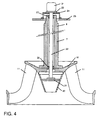
- Figure 4 shows an arrangement similar to the arrangement of Figure 3 except that cone 20 and support 21 are directly fastened to shaft 22.
- the opposite end of shaft 22 is connected, however, to the output of a motor 31 which is mounted directly on bracket 24 which in turn is fixed to generator end cover 25.
- Motor 31 may be operated to rotate shaft 22, support 21, and cone 20 in either direction.
- Figure 5 shows a modification in which fins or vanes 32 are mounted around the surface of the frustoconical cone extending axially from the apex to the base of the cone and projecting vertically outwardly.
- Figures 6 and 7 show a modified type of transition member comprising an outer cone 33 and an inner cone 34.
- Inner cone 34 is fitted with fins 35 similar to fins 32 in Figure 5.
- Outer cone 33 is provided with slots which receive fins 35.
- Outer cone 33 is carried on a support 36 which is on the end of shaft 22.
- Inner cone 34 is carried by a support 37 which is attached to a servo 38 that is axially movable on shaft 22.
- servo 38 is actuated to move to the lower position as shown in Figure 8
- inner cone 34 is carried downwardly to nest against the inside of outer cone 33 with fins 35 projecting as shown in Figure 7.
- Figure 8 shows a modified form of cone in which the outer surface has alternating lands 39 and grooves 40.
- cone 20 When the turbine as shown in Figure 2 is in operation, cone 20 is in fixed position when runner 10 is rotating under load. Water which comes through blades 11 will not be given a rotational component by cone 20 since it is fixed against rotation, thereby tending to avoid generation of a vortex rope. If the surface of cone 20 is roughened by providing fins, or ridges, and grooves as shown in Figures 5 and 8, a greater bite will be taken on the water flowing past the transition member. The cone may be converted between a smooth surface and a roughened surface by providing retractable fins as shown in Figures 6 and 7.
- the effect of the cone upon swirling of the water scream may be enhanced by rotating the cone independently of rotation of the runner, by drive motor 28 ( Figure 3) or drive motor 31 ( Figure 4). If the vortex rope is rotating in the same direction as the runner, cone 20 may be driven in the opposite direction to counteract the swirling motion. If the vortex rope is swirling in a direction opposite the direction of the runner, the cone may be driven in the same direction as the runner but at a higher speed. Also the effect of the transition member upon the water flow may be changed or modulated by use of retractable fins as shown in Figures 6 and 7.
Landscapes
- Engineering & Computer Science (AREA)
- Chemical & Material Sciences (AREA)
- Combustion & Propulsion (AREA)
- Mechanical Engineering (AREA)
- General Engineering & Computer Science (AREA)
- Hydraulic Turbines (AREA)
- Water Treatment By Electricity Or Magnetism (AREA)
- Engine Equipment That Uses Special Cycles (AREA)
- Braking Arrangements (AREA)
Claims (10)
- Wasserturbine mit einer Wasserzufuhrleitung und einem drehbaren Läufer (10) mit einer Vielzahl von Schaufeln (11), mit einem Leitelement (12; 20; 33), das stromabwärts des Läufers (10) angeordnet ist, um über die Turbinenschaufeln fließendes Wasser zu kanalisieren, dadurch gekennzeichnet, daß das Leitelement (20; 33) unabhängig von der Drehung des Läufers (10) gelagert ist.
- Wasserturbine nach Anspruch 1, wobei das Leitelement (20; 33) auf Wellenmitteln (22) angeordnet ist, die koaxial mit der den Läufer (10) tragenden Welle verlaufen.
- Wasserturbine nach Anspruch 2, wobei die Wellenmittel (22) sich axial durch den Läufer (10) und durch die den Läufer (10) tragende Welle erstrecken.
- Wasserturbine nach einem der vorhergehenden Ansprüche, wobei das Leitelement (20; 33) fest gegen Drehung gesichert ist.
- Wasserturbine nach einem der Ansprüche 1 bis 3, wobei das Leitelement (20; 33) drehbar angeordnet ist und durch Antriebsmittel (28; 31) drehend angetrieben wird.
- Wasserturbine nach Anspruch 5, wobei das Antriebsmittel (28; 31) reversierbar ist, um das Leitelement (20; 33) in beide Richtungen zu drehen.
- Wasserturbine nach einem der vorhergehenden Ansprüche, wobei das Leitelement (20; 33) eine aufgerauhte Oberfläche zur Einwirkung auf an dem Leitelement vorbeifließendes Wasser aufweist.
- Wasserturbine nach Anspruch 7, wobei die aufgerauhte Oberfläche eine Anordnung von Schaufeln (Finnen) (32 oder 35) zur Beeinflussung von an dem Leitelement vorbeifließendem Wasser aufweist.
- Wasserturbine nach Anspruch 8, wobei die Schaufeln (35) einstellbar sind, um den Rauhheitsgrad der Oberfläche des Leitelements (33) zu variieren.
- Wasserturbine nach Anspruch 9, wobei die Schaufeln (35) auf einem beweglichen Träger (34) angeordnet sind, um zwischen einer Stellung, in der sie in das Leitelement (33) zurückgezogen sind, wobei eine glatte Oberfläche des Leitelements geschaffen wird, und einer Stellung, in der sie über die Oberfläche des Leitelementes hervorstehen, um eine rauhe Oberfläche zu erzeugen, verstellbar sind.
Applications Claiming Priority (3)
| Application Number | Priority Date | Filing Date | Title |
|---|---|---|---|
| US822067 | 1992-01-17 | ||
| US07/822,067 US5261787A (en) | 1992-01-17 | 1992-01-17 | Water turbines and water flow transition members therefor |
| PCT/US1993/000615 WO1993014315A1 (en) | 1992-01-17 | 1993-01-19 | Runner hub |
Publications (2)
| Publication Number | Publication Date |
|---|---|
| EP0621923A1 EP0621923A1 (de) | 1994-11-02 |
| EP0621923B1 true EP0621923B1 (de) | 1996-05-15 |
Family
ID=25235038
Family Applications (1)
| Application Number | Title | Priority Date | Filing Date |
|---|---|---|---|
| EP93904595A Expired - Lifetime EP0621923B1 (de) | 1992-01-17 | 1993-01-19 | Wasserturbine |
Country Status (7)
| Country | Link |
|---|---|
| US (1) | US5261787A (de) |
| EP (1) | EP0621923B1 (de) |
| AT (1) | ATE138158T1 (de) |
| AU (1) | AU3590493A (de) |
| DE (1) | DE69302676T2 (de) |
| ES (1) | ES2089798T3 (de) |
| WO (1) | WO1993014315A1 (de) |
Cited By (1)
| Publication number | Priority date | Publication date | Assignee | Title |
|---|---|---|---|---|
| EP1624184A2 (de) | 2004-08-05 | 2006-02-08 | Voith Siemens Hydro Power Generation GmbH & Co. KG | Hydraulische Turbine oder Pumpturbine |
Families Citing this family (17)
| Publication number | Priority date | Publication date | Assignee | Title |
|---|---|---|---|---|
| US5905311A (en) * | 1997-01-22 | 1999-05-18 | Voith Hydro, Inc. | Integrated hydroelectric unit |
| DE19906123B4 (de) * | 1999-02-13 | 2004-06-24 | Voith Siemens Hydro Power Generation Gmbh & Co. Kg | Verfahren zur Vergrößerung des Arbeitsbereiches von geführten Strömungen |
| EP1209356A1 (de) | 2000-11-22 | 2002-05-29 | VA TECH HYDRO GmbH & Co. | Turbine oder Pumpturbine |
| CA2358722A1 (fr) * | 2001-10-11 | 2003-04-11 | Alstom Canada Inc. | Turbine hydraulique avec tourbillon centripete et distributeur axial |
| US6918744B2 (en) * | 2002-08-21 | 2005-07-19 | Alexander Gokhman | Hydraulic turbine and exit stay apparatus therefor |
| US7095597B1 (en) * | 2003-04-30 | 2006-08-22 | Clipper Windpower Technology, Inc. | Distributed static var compensation (DSVC) system for wind and water turbine applications |
| US7035718B2 (en) * | 2004-01-27 | 2006-04-25 | General Electric Company | Method and System for detecting and reducing draft tube pressure fluctuations |
| DE102006043946A1 (de) * | 2006-09-14 | 2008-03-27 | Oswald Elektromotoren Gmbh | Turbinenvorrichtung |
| US20090087305A1 (en) * | 2007-09-28 | 2009-04-02 | Alexander Gokhman | Exit stay apparatus with intermediate flange |
| FR2928422B1 (fr) * | 2008-03-05 | 2013-07-05 | Alstom Hydro France | Roue francis de turbine hydraulique equipee d'un organe formant pointe et procede de reduction des fluctuations utilisant une telle roue. |
| KR101507320B1 (ko) * | 2008-03-05 | 2015-03-31 | 알스톰 르네와블 테크놀로지즈 | 수압 기계의 휠의 크라운이나 허브에 부착될 수 있는 부재 및 이를 구비한 휠과 수압 기계 |
| CZ2011107A3 (cs) | 2011-03-02 | 2012-09-12 | Kreidl@František | Lopatkový stroj |
| CN103244336B (zh) * | 2013-05-21 | 2016-03-09 | 吴春根 | 一种水电站尾水发电水轮机 |
| CN103967686A (zh) * | 2014-05-26 | 2014-08-06 | 哈尔滨电机厂有限责任公司 | 一种减弱尾水管压力脉动的混流式水轮机泄水锥 |
| AU2018293589C1 (en) * | 2017-06-29 | 2023-06-29 | Henry K. Obermeyer | Improved reversible pump-turbine installation |
| CN109538307B (zh) * | 2018-12-16 | 2022-03-04 | 中国航发沈阳发动机研究所 | 一种调节气流机匣 |
| JP7360357B2 (ja) * | 2020-05-12 | 2023-10-12 | 株式会社東芝 | ランナコーンおよび水力機械 |
Family Cites Families (12)
| Publication number | Priority date | Publication date | Assignee | Title |
|---|---|---|---|---|
| US198429A (en) * | 1877-12-18 | Improvement in turbine wheels | ||
| US1055588A (en) * | 1912-02-10 | 1913-03-11 | Albert Baldwin Wood | Hydraulic turbine. |
| US1748768A (en) * | 1915-06-02 | 1930-02-25 | Allis Chalmers Mfg Co | Water turbine with a high specific speed |
| US1583415A (en) * | 1918-06-28 | 1926-05-04 | Moody Lewis Ferry | Hydraulic turbine |
| US1803220A (en) * | 1929-07-24 | 1931-04-28 | Thompson Thomas | Water turbine |
| US1987082A (en) * | 1932-03-18 | 1935-01-08 | Baldwin Southwark Corp | Plate steel head cover |
| US2662726A (en) * | 1947-04-30 | 1953-12-15 | Percy H Thomas | Intermittent impact water wheel |
| US3386155A (en) * | 1963-07-01 | 1968-06-04 | Dominion Eng Works Ltd | Method of fitting seal rings to blades |
| US4017211A (en) * | 1975-09-17 | 1977-04-12 | Aktiebolaget Karlstads Mekaniska Werkstad | Runner for hydrodynamic machines |
| JPS54138928A (en) * | 1978-04-19 | 1979-10-27 | Hitachi Ltd | Runner |
| DE2905555A1 (de) * | 1979-02-14 | 1980-08-21 | Willy Minnich | Vorrichtung zum verringern der randwirbelstaerke an flugzeugen und schiffen |
| JPS5781164A (en) * | 1980-11-07 | 1982-05-21 | Toshiba Corp | Exhaust equipment for multi-stage hydraulic machine |
-
1992
- 1992-01-17 US US07/822,067 patent/US5261787A/en not_active Expired - Fee Related
-
1993
- 1993-01-19 AU AU35904/93A patent/AU3590493A/en not_active Abandoned
- 1993-01-19 ES ES93904595T patent/ES2089798T3/es not_active Expired - Lifetime
- 1993-01-19 DE DE69302676T patent/DE69302676T2/de not_active Expired - Fee Related
- 1993-01-19 WO PCT/US1993/000615 patent/WO1993014315A1/en not_active Ceased
- 1993-01-19 AT AT93904595T patent/ATE138158T1/de not_active IP Right Cessation
- 1993-01-19 EP EP93904595A patent/EP0621923B1/de not_active Expired - Lifetime
Cited By (1)
| Publication number | Priority date | Publication date | Assignee | Title |
|---|---|---|---|---|
| EP1624184A2 (de) | 2004-08-05 | 2006-02-08 | Voith Siemens Hydro Power Generation GmbH & Co. KG | Hydraulische Turbine oder Pumpturbine |
Also Published As
| Publication number | Publication date |
|---|---|
| WO1993014315A1 (en) | 1993-07-22 |
| US5261787A (en) | 1993-11-16 |
| DE69302676T2 (de) | 1996-10-10 |
| EP0621923A1 (de) | 1994-11-02 |
| ES2089798T3 (es) | 1996-10-01 |
| DE69302676D1 (de) | 1996-06-20 |
| ATE138158T1 (de) | 1996-06-15 |
| AU3590493A (en) | 1993-08-03 |
Similar Documents
| Publication | Publication Date | Title |
|---|---|---|
| US5261787A (en) | Water turbines and water flow transition members therefor | |
| US7893555B2 (en) | Wind power current generator | |
| JP5258774B2 (ja) | 風力発電装置、大気から電力を発生させるための発電機、及び、移動する大気から電力を発生させるための方法 | |
| US4585950A (en) | Wind turbine with multiple generators | |
| US4162410A (en) | Vertical-axis windmill | |
| EP0086076B1 (de) | Windrad mit waagerechter Welle und aerodynamischer Steuerung des Blattanstellwinkels | |
| CA2067872A1 (en) | Wind turbine | |
| US6926494B2 (en) | Hydraulic turbine with increased power capacities | |
| US20030223857A1 (en) | Hydraulic turbine feed tank | |
| GB2275970A (en) | Vertical axis wind turbines | |
| KR102147538B1 (ko) | 회오리 유도 발전장치 | |
| AU2006268899B2 (en) | Turbine for a hydroelectric power station | |
| KR102026954B1 (ko) | 집풍식 풍력발전시스템 | |
| US6949842B2 (en) | Centrifugal weight control for a wind or water turbine | |
| CN220815907U (zh) | 一种集成式风力发电机的风罩构件 | |
| RU2245456C2 (ru) | Ветроэнергетическая установка с вертикальной осью вращения | |
| US2972469A (en) | Thrust reducing means for turbines, pumps and pump-turbines | |
| KR100755737B1 (ko) | 다중 나선형 풍력 발전장치 | |
| CN116601385A (zh) | 海上发电系统 | |
| US20120051902A1 (en) | Hydro turbine | |
| RU2791360C1 (ru) | Вертикальная ветроэнергетическая установка | |
| CA2434761C (en) | Hydraulic turbine with increased power capacities | |
| KR102960619B1 (ko) | 듀얼 풍력 발전장치 | |
| RU2162545C2 (ru) | Саморегулирующаяся ветротурбина | |
| US12006909B2 (en) | Horizontal axis wind turbine and method for generating electrical energy |
Legal Events
| Date | Code | Title | Description |
|---|---|---|---|
| PUAI | Public reference made under article 153(3) epc to a published international application that has entered the european phase |
Free format text: ORIGINAL CODE: 0009012 |
|
| 17P | Request for examination filed |
Effective date: 19940816 |
|
| AK | Designated contracting states |
Kind code of ref document: A1 Designated state(s): AT BE CH DE DK ES FR GB GR IE IT LI LU MC NL PT SE |
|
| RBV | Designated contracting states (corrected) |
Designated state(s): AT CH DE ES FR GB IT LI SE |
|
| 17Q | First examination report despatched |
Effective date: 19950804 |
|
| GRAH | Despatch of communication of intention to grant a patent |
Free format text: ORIGINAL CODE: EPIDOS IGRA |
|
| GRAA | (expected) grant |
Free format text: ORIGINAL CODE: 0009210 |
|
| AK | Designated contracting states |
Kind code of ref document: B1 Designated state(s): AT CH DE ES FR GB IT LI SE |
|
| REF | Corresponds to: |
Ref document number: 138158 Country of ref document: AT Date of ref document: 19960615 Kind code of ref document: T |
|
| REF | Corresponds to: |
Ref document number: 69302676 Country of ref document: DE Date of ref document: 19960620 |
|
| ITF | It: translation for a ep patent filed | ||
| ET | Fr: translation filed | ||
| REG | Reference to a national code |
Ref country code: ES Ref legal event code: FG2A Ref document number: 2089798 Country of ref document: ES Kind code of ref document: T3 |
|
| REG | Reference to a national code |
Ref country code: ES Ref legal event code: FG2A Ref document number: 2089798 Country of ref document: ES Kind code of ref document: T3 |
|
| PLBE | No opposition filed within time limit |
Free format text: ORIGINAL CODE: 0009261 |
|
| STAA | Information on the status of an ep patent application or granted ep patent |
Free format text: STATUS: NO OPPOSITION FILED WITHIN TIME LIMIT |
|
| 26N | No opposition filed | ||
| PGFP | Annual fee paid to national office [announced via postgrant information from national office to epo] |
Ref country code: FR Payment date: 19990118 Year of fee payment: 7 |
|
| PGFP | Annual fee paid to national office [announced via postgrant information from national office to epo] |
Ref country code: SE Payment date: 19990125 Year of fee payment: 7 |
|
| PGFP | Annual fee paid to national office [announced via postgrant information from national office to epo] |
Ref country code: ES Payment date: 19990127 Year of fee payment: 7 |
|
| PGFP | Annual fee paid to national office [announced via postgrant information from national office to epo] |
Ref country code: DE Payment date: 19990129 Year of fee payment: 7 |
|
| PGFP | Annual fee paid to national office [announced via postgrant information from national office to epo] |
Ref country code: AT Payment date: 19990131 Year of fee payment: 7 |
|
| PGFP | Annual fee paid to national office [announced via postgrant information from national office to epo] |
Ref country code: GB Payment date: 19990201 Year of fee payment: 7 |
|
| PGFP | Annual fee paid to national office [announced via postgrant information from national office to epo] |
Ref country code: CH Payment date: 19990401 Year of fee payment: 7 |
|
| PG25 | Lapsed in a contracting state [announced via postgrant information from national office to epo] |
Ref country code: GB Free format text: LAPSE BECAUSE OF NON-PAYMENT OF DUE FEES Effective date: 20000119 Ref country code: AT Free format text: LAPSE BECAUSE OF NON-PAYMENT OF DUE FEES Effective date: 20000119 |
|
| PG25 | Lapsed in a contracting state [announced via postgrant information from national office to epo] |
Ref country code: SE Free format text: LAPSE BECAUSE OF NON-PAYMENT OF DUE FEES Effective date: 20000120 Ref country code: ES Free format text: LAPSE BECAUSE OF NON-PAYMENT OF DUE FEES Effective date: 20000120 |
|
| PG25 | Lapsed in a contracting state [announced via postgrant information from national office to epo] |
Ref country code: LI Free format text: LAPSE BECAUSE OF NON-PAYMENT OF DUE FEES Effective date: 20000131 Ref country code: CH Free format text: LAPSE BECAUSE OF NON-PAYMENT OF DUE FEES Effective date: 20000131 |
|
| GBPC | Gb: european patent ceased through non-payment of renewal fee |
Effective date: 20000119 |
|
| EUG | Se: european patent has lapsed |
Ref document number: 93904595.1 |
|
| REG | Reference to a national code |
Ref country code: CH Ref legal event code: PL |
|
| PG25 | Lapsed in a contracting state [announced via postgrant information from national office to epo] |
Ref country code: FR Free format text: LAPSE BECAUSE OF NON-PAYMENT OF DUE FEES Effective date: 20000929 |
|
| PG25 | Lapsed in a contracting state [announced via postgrant information from national office to epo] |
Ref country code: DE Free format text: LAPSE BECAUSE OF NON-PAYMENT OF DUE FEES Effective date: 20001101 |
|
| REG | Reference to a national code |
Ref country code: FR Ref legal event code: ST |
|
| REG | Reference to a national code |
Ref country code: ES Ref legal event code: FD2A Effective date: 20011010 |
|
| PG25 | Lapsed in a contracting state [announced via postgrant information from national office to epo] |
Ref country code: IT Free format text: LAPSE BECAUSE OF NON-PAYMENT OF DUE FEES Effective date: 20050119 |