EP0621654A2 - Réseau d'antennes du type actif - Google Patents
Réseau d'antennes du type actif Download PDFInfo
- Publication number
- EP0621654A2 EP0621654A2 EP94302699A EP94302699A EP0621654A2 EP 0621654 A2 EP0621654 A2 EP 0621654A2 EP 94302699 A EP94302699 A EP 94302699A EP 94302699 A EP94302699 A EP 94302699A EP 0621654 A2 EP0621654 A2 EP 0621654A2
- Authority
- EP
- European Patent Office
- Prior art keywords
- antenna
- array
- antenna array
- circuit
- active antenna
- Prior art date
- Legal status (The legal status is an assumption and is not a legal conclusion. Google has not performed a legal analysis and makes no representation as to the accuracy of the status listed.)
- Withdrawn
Links
Images

Classifications
-
- H—ELECTRICITY
- H01—ELECTRIC ELEMENTS
- H01Q—ANTENNAS, i.e. RADIO AERIALS
- H01Q21/00—Antenna arrays or systems
- H01Q21/0087—Apparatus or processes specially adapted for manufacturing antenna arrays
-
- H—ELECTRICITY
- H01—ELECTRIC ELEMENTS
- H01Q—ANTENNAS, i.e. RADIO AERIALS
- H01Q21/00—Antenna arrays or systems
- H01Q21/0006—Particular feeding systems
- H01Q21/0025—Modular arrays
Definitions
- the present invention relates to an antenna array, and, more particularly, to an active antenna array for use with a radar guided missile, for example.
- an on-board radar system directs a radar beam towards the target and reflected energy received and processed maintains the missile on the desired intercept course.
- the sophistication of avoidance and jamming techniques which can be employed for the benefit of the target in order to avoid a guided missile seeker or redirect it along a non-intercept course, have made it necessary to improve the missile seeker in order to overcome these defensive measures and enhance the probability of successful target intercept.
- Typical defensive measures produce false radar return signals, having the purpose of confusing the missile guidance system as to the actual target.
- a well-known guidance system typically referred to as a gimballed seeker, mounts a high gain antenna on a gimbal assembly to allow the seeker to be pointed over a relatively large solid angle or scan volume.
- a servo system drives the gimbal which allows positioning of the antenna for both transmission and receipt of radar energy in a desired direction vithin the scan volume.
- the weight, cost, excessive volume and mechanical complexity of such systems make replacement desirable.
- gimballed systems have traditionally had to be custom designed and fabricated for each new application.
- ESA electronically scanned antenna
- passive ESA the high RF power is developed in a separate transmitter unit and then partitioned among the numerous phase shifting elements. Since the phase shifting function is performed at relatively high power, the phase shifters tend to have high losses.
- this ESA approach lacks the flexibility required to fully utilize modern signal processing techniques that require access to multiple sub-arrays of the full aperture.
- a second ESA approach uses high power amplifiers and low noise amplifiers to develop the transmit and receive signals, respectively, for groups of antenna radiating and receive elements. This latter approach has many of the same difficulties as the passive ESA and still does not provide fully independent radiating/receive elements in the array.
- a guided missile In addition to accurately guiding to intercept the target, a guided missile typically carries a warhead payload that is designed to maximize damage to the target under attack. To increase the probability of taking out the target, accurate data is needed at intercept to determine the optimum burst point for the warhead.
- Existing missile seekers used for guidance are not capable of collecting the precise data required to compute the optimum burst point for the missile warhead.
- a second highly specialized sensor is included in the missile design to gather this required data. It would be desirable to be able to accomplish this function with the missile seeker, thus eliminating the need for a separate radar system, both because of additional cost and weight of such a system as well as the taking up of additional space on-board the missile.
- AESA active electronically scanned array
- the AESA is constructed of individual active transmit/receive modules. Each module consists of a transmitter element and a radar receive element which are individually adjustable as to phase and gain. These basic building blocks may be combined together to form an array of any size without having to incur a large design cost. By use of modular construction, it is possible to provide active antenna arrays of any desired size by merely assembling the appropriate number of modules.
- Wide bandwidth is inherent in the basic design of the active transmit/receive (T/R) modules, and they are capable of operating over bands that are tens of percent wide. Their ability to operate over such wide bandwidths allows the missile seeker to derive passive guidance information against various emitters operating on-board the target.
- the wide bandwidth supports active operation over a wider bandwidth, which provides enhanced performance in scenarios with multiple missiles in flight simultaneously or in high RFI (i.e., radio frequency interference) environments.
- a wider operating bandwidth may also provide performance advantages against some electronic counter measures (ECM) techniques. Forcing an ECM device to operate over a wider bandwidth may dilute the jamming power received by the missile seeker receiver.
- ECM electronic counter measures
- the AESA is capable of adjusting the gain and phase of the individual elements of the active array to steer antenna nulls in real-time to eliminate the interference from off-axis stand-off jammers. With reduced interference, the probability of successful guidance to the desired target is enhanced.
- the array may be partitioned into multiple sub-arrays which by the use of appropriate signal processing can achieve improved guidance to a specific target located within a cluster of targets.
- the seeker With separate transmission and receiving capabilities as well as individual phase and gain control for each antenna element, the seeker can resolve signals received from a large number of independent targets. Furthermore, the resolution capability is not dependent upon the returns coming from comparably sized targets.
- the same missile radar system used to detect and track targets can be used to collect the data requisite for computing the optimum burst point for the missile payload warhead.
- the inherent features of the active T/R module design which allow the fuzing function to be combined with the radar seeker are the small blind range (fast recovery time after transmit), the wide bandwidth of the T/R modules which supports waveforms that are capable of making precision measurements of target dimensions, and the agility of pointing the seeker beam to interrogate the target dimensions.
- the AESA is typically composed of 100 or more active elements. Each element has inherently high reliability, but in addition, the failure of a single element may be compensated for by adjusting the parameters of gain and phase of the "nearest neighbors". This feature provides graceful performance degradation as individual elements fail.
- high power seekers that use travelling-wave tube (TWT) technology typically require that the seeker be pressurized in order to preclude transmitter arcing and subsequent failure. Any failure of the pressure seal will result in catastrophic failure of the missile seeker. Because each T/R module has a lower peak power, the requirement for pressurization to preclude arcing is eliminated.
- the active T/R modules use much lower voltages than the TWT transmitter which commonly requires voltages on the order of ten thousand (10,000) volts to operate.
- an AESA eliminates the moving parts that are part of a conventional gimballed antenna. The elimination of the gimbal assembly with the accompanying torquer motors and high-powered servo electronics will provide a marked enhancement in reliability.
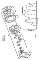
- FIG. 1 shows in an exploded view the various parts of a typical prior art gimballed radar seeker system for guiding a missile enumerated generally as 10.
- the system includes, at the forward end, an antenna array 12 consisting of individual antenna elements (or slots) 14 in a general matrix arrangement, and various interconnection and electronic circuit means collectively identified as 16.
- a servomechanism drive 22, with associated control and drive electronics 24, is typically combined with an RF processor 26.
- the seeker assembly 10 can be operated to scan over a given solid angle and thereby enlarge the angular coverage that would be accorded to an antenna array 12 fixed in position.
- Such a gimballed antenna array system typically has from two to four reception channels, and is highly tuned in frequency with a relatively narrow operating frequency range.
- the radar echo or response 28 received directly along antenna boresight (often called the mainlobe response) is the largest, but for angles away from the mainlobe, the signal return for high powered off-boresight signals may still be significant (e.g., 30,32).
- These responses away from the mainlobe peak are usually referred as antenna sidelobes or just sidelobes. Also, it is to be noted that between adjacent lobes there are points of zero reception 34, or "nulls". In practice, a signal located at the same angle or position as a null would not be sensed.
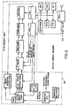
- an electronically scanned antenna (ESA) in the so-called passive form is seen to consist of a large number of antenna elements 36 arranged in a matrix 38 with phase control apparatus 40 which enables collectively changing the phase of the signals received or transmitted from the antenna elements.
- ESA electronically scanned antenna
- This approach offers a limited amount of control and processing. Since the phase shift function is performed at high power, a substantial amount of loss typically occurs across the phase shifter elements of apparatus 40.
- a phase control 44 again provides phase change across an antenna array 46, with a low noise amplifier 48 (LNA) provided for the return signals and additional separate amplifying means 50 provided for the transmitting signal from the exciter (FIG. 3B).
- LNA low noise amplifier
- Each low noise amplifier 48 is seen to include a limiter 52, an amplifier 54 and a control 56 for the amplifier (FIG. 3D).
- Hybrid ESAs have problems similar to passive ESAs in that the phase shift function is implemented at high RF power.
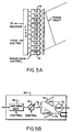
- FIGS. 4 and 5 where an active array to be described is enumerated generally as 58.
- a wideband antenna array composed of a plurality of individual antenna elements 60 which, for exemplary purposes only, will be considered to number one hundred (100). They are depicted as flared-notch type elements but may assume a variety of different known forms and be suitable for present purposes. It is important to note that the individual antenna elements are not secured to a single background, however, they are arranged in a modular form with each module including an antenna element. In this way, an antenna array can be made up of any desired size by merely utilizing the necessary number of antenna elements for the desired array.
- module array and cold plate assembly 62 consisting of individual modules 64, one for each antenna element.
- Each module 64 includes at its forward facing surface can be mated with a corresponding element 60 from the broadband antenna array, serving both to physically and electrically interconnect the module array and cold plate assembly modules to the antenna array modules.
- the cold plate assembly identified separately as 65, can be constructed in a number of different well known ways, e.g., circulating coolant, change of phases material, or heat pipes.
- the individual antenna elements are connected through separate modules 64, identified generally as T/R (transmit/receive) modules, which individually contain the circuits shown in FIG. 5B. More particularly, interconnection with the antenna element is initially via a duplexer 70 which, in a way well known in the art, interconnects outgoing radar signals from a high-power amplifier 72 (HPA) to the associated antenna element 60 for transmit and interconnects reflected radar signals from the same antenna element 60 to a low noise amplifier 74 (LNA) for receive. These signals interconnect through the duplexing switch 75 to a common line consisting of a serially arranged variable phase control 76 and a variable gain control 78.
- HPA high-power amplifier
- LNA low noise amplifier
- both the amplitude and phase of each signal as applied to or received from each antenna element can be separately controlled as to phase and amplification.
- phase and gain control is performed prior to the high power amplifier, phase and gain control are implemented at lower power and can be accomplished with low loss.
- each of the modules in the module array and cold plate assembly 62 receives necessary RF and logic control signals from the RF and logic distribution network 80.
- adaptive processing and monopulse network circuits 82 are incorporated with four major blocks or modules similarly mounted to and electrically connected with the RF and logic control distribution network 80 from the rear side.
- the cold plate assembly 60 in addition to effecting desired electrical connections, also provides cooling to the rearward parts of the modular radar missile seeker of this invention, i.e., the RF and logic distribution network 80 and the monopulse network circuit 82.
- each T/R module 64 is built into a complete, stand-alone assembly incorporating all of the required functions and which assembly has the overall form of a generally rectangular prism.
- the various functional blocks i.e., limiter, high power amplifier, low noise amplifier, phase and gain adjustment, interface circuits, for example, are included within each module and are laid out over the depth of the assembly housing 84 (i.e., extending along the direction from the antenna to the circuits 82).
- the rigid cold plate 66 is secured to the rear surface of each module 64.
- An alternative embodiment of modular construction is obtained where a plurality of wafer modules are sandwiched together, each wafer having a given number of identical and separate function block elements (e.g., limiter, low noise amplifiers) arranged in a matrix pattern.
- a necessary number of interconnection means are provided on one major surface of each wafer to enable interconnection of the wafers to each other.
- the cold plate can be identical to cold plate 66 described in connection with the first embodiment.
- each module is determined essentially by the spacing of the antenna elements 60. Correlating the module sizes to the antenna element spacing enables direct assembly of the modular array to the antenna array on a one to one basis.
- the present invention provides numerous advantages that are not attainable with the known systems, including: (1) a modular and cost effective approach to achieving seeker power-aperture product, (2) wide bandwidth providing integrated active/passive (ARH) guidance, (3) adaptive beam formation to enhance seeker guidance in the presence of, say, stand-off jammers (SOJs), (4) enhanced guidance against clustered targets, (5) seeker-based fuzing, i.e., integrating guidance and fuzing functions into a single seeker, and (6) improved reliability and graceful performance degradation through functional redundancy and real-time adaptive compensation for failed elements in the array.
- ARH integrated active/passive
- SOJs stand-off jammers
- the present invention is constructed of individual active transmit/receive modules with each module consisting of a transmitter element and a sensitive radar receive element. These basic building blocks may be combined together to form an array of any size without having to incur a large design cost. Since the basic parts are made in modular form, the cost of any given radar missile seeker is substantially reduced in that it merely requires the assembly of a given number of modules to produce the system and does not require a completely customized design. As a further result of the modular construction, both the non-recurring and recurring cost of new seeker development is reduced.
- T/R modules as building blocks provides a modular approach to achieving increased power-aperture product.
- increasing the size of the array increases both the transmitter power and the antenna gain simultaneously.
- significant increase in the power-aperture product involve design efforts directed toward developing high powered transmitters and/or larger antennas.
- the wide bandwidth of the preferred embodiment provides enhanced performance in scenarios with multiple missiles in flight simultaneously or in high radio frequency interference RFI environments.
- a wider operating bandwidth may also provide performance advantages against some electronic countermeasures (ECM) techniques. Forcing an ECM device to operate over a wider bandwidth tends to dilute the jamming power in the missile seeker receiver.
- ECM electronic countermeasures
- the conventional gimballed seeker has a fixed antenna sidelobe response that is not capable of being modified in real-time to counter various defensive techniques that may be employed.
- One method available in the prior art to overcome this problem is to modify the flight path of the missile in an attempt to adjust the geometry with respect to interfering sources and place them in an antenna null. In the process of doing this, however, overall missile performance is frequently degraded.
- the preferred embodiment enables adjusting both the gain and phase of the individual elements of the active array to steer antenna nulls in real-time and in that way eliminate the interference from off-axis stand-off jammers, and this is all accomplished without modifying the missile flight path. With reduced interference, the probability of successful guidance to the desired target is enhanced.
- a conventional gimballed seeker has limited performance against target clusters in that the antenna array is typically divided into four quadrants which are either combined and then processed or processed separately. Only a maximum of three targets can be successfully resolved by this method.
- the array may be partitioned into multiple sub-arrays which by the use of appropriate signal processing can achieve improved guidance to a specific target located within a cluster of targets.
- the number of sub-arrays is determined by the size of the array and the complexity of the feed network, but theoretically can be made arbitrarily large within the packaging constraints required for signal processing.
- the seeker With separate transmission and receiving capabilities as well as individual phase and gain control for each antenna element, the seeker can resolve signals received from a large number of independent targets. Further, by utilizing modern signal processing techniques, the resolution capability is not dependent upon the returns coming from comparably sized targets.
- the fuzing and guidance functions are not practicable to combine the fuzing and guidance functions into a single seeker.
- the limiting factors include the blind range of the high power seeker, the limited bandwidth of operation, and the difficulty in positioning the beam at rates consistent with attempting to scan the target to determine optimum burst point.
- the same missile radar system used to detect and track targets can be used to collect the data requisite for computing the optimum burst point for the missile payload warhead.
- the inherent features of the active T/R design which allow the fuzing function to be combined with the radar seeker are the small blind range (fast recovery time after transmit), the wide bandwidth of the T/R modules which supports waveforms that are capable of making precision measurements of target dimensions, and the agility of pointing the seeker beam to interrogate the target dimensions.
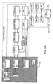
- FIGS. 1 and 4 it can be seen that a substantial reduction in hardware complexity is obtained by use of the present invention over the prior art gimballed pedestal system. More particularly, as seen in FIG. 3A, the equipment specifically required for a conventional missile seeker with a gimballed antenna are those items located in the shaded functional block diagram enumerated 86. Comparing with FIG. 6, the gimbal torquer motors, servo electronics and other mechanical appurtenances necessary for operation of this prior art system have been eliminated and, in their place, there are predominantly lightweight and relatively inexpensive electronic components and circuits shown enclosed in the dotted line part of the circuit enumerated as 88. The remainder of the circuit equipment in both cases (i.e., outside 86 and 88) is very much the same for both the gimballed and present invention.
- AESA Enhanced gimballed array
- failure of any one of a number of critical components will result in failure of the guided missile to be able to complete its mission.
- the AESA because it typically is composed of 100 or more identical active modular elements, will display graceful degradation upon the failure of any single element.
- Each element has inherently high reliability, and seeker system reliability is further enhanced since the failure of a single element may be compensated for by adjusting the parameters of gain and phase of its "nearest neighbors". This feature provides the highly advantageous graceful performance degradation.
- TWT travelling-wave tube
- conventional high power gimballed seekers that use travelling-wave tube (TWT) technology typically require that the seeker be pressurized in order to preclude transmitter arcing and subsequent catastrophic failure. In this case, any failure of the pressure seal will result in failure of the missile seeker and, accordingly, failure of the missile to complete its mission.
- TWT travelling-wave tube
- each T/R module has a lower peak power, the requirement for pressurization to preclude arcing is eliminated.
- the active T/R modular technology uses much lower voltages than a TWT transmitter which commonly requires voltages on the order of ten thousand (10,000) volts to operate. Such high voltages require extremely sophisticated manufacturing techniques to ensure that power supply related failures do not occur.
Applications Claiming Priority (2)
| Application Number | Priority Date | Filing Date | Title |
|---|---|---|---|
| US4793793A | 1993-04-19 | 1993-04-19 | |
| US47937 | 1993-04-19 |
Publications (2)
| Publication Number | Publication Date |
|---|---|
| EP0621654A2 true EP0621654A2 (fr) | 1994-10-26 |
| EP0621654A3 EP0621654A3 (fr) | 1995-03-22 |
Family
ID=21951838
Family Applications (1)
| Application Number | Title | Priority Date | Filing Date |
|---|---|---|---|
| EP94302699A Withdrawn EP0621654A3 (fr) | 1993-04-19 | 1994-04-15 | Réseau d'antennes du type actif. |
Country Status (4)
| Country | Link |
|---|---|
| EP (1) | EP0621654A3 (fr) |
| JP (1) | JPH0779116A (fr) |
| CA (1) | CA2121153A1 (fr) |
| NO (1) | NO941401L (fr) |
Cited By (5)
| Publication number | Priority date | Publication date | Assignee | Title |
|---|---|---|---|---|
| WO1997023923A1 (fr) * | 1995-12-21 | 1997-07-03 | The Boeing Company | Antenne reseau a commande de phase pour communications a faible cout |
| US6828932B1 (en) | 2003-01-17 | 2004-12-07 | Itt Manufacutring Enterprises, Inc. | System for receiving multiple independent RF signals having different polarizations and scan angles |
| US8570237B2 (en) | 2011-02-01 | 2013-10-29 | Raytheon Company | Multi-band electronically scanned array antenna |
| WO2015068909A1 (fr) * | 2013-11-07 | 2015-05-14 | Samsung Techwin Co., Ltd | Procédé et appareil de comptage de personnes |
| CN115070407A (zh) * | 2022-05-18 | 2022-09-20 | 电子科技大学 | 辅助天线阵面大规模阵元组装定位方法 |
Families Citing this family (5)
| Publication number | Priority date | Publication date | Assignee | Title |
|---|---|---|---|---|
| US6205224B1 (en) * | 1996-05-17 | 2001-03-20 | The Boeing Company | Circularly symmetric, zero redundancy, planar array having broad frequency range applications |
| EP2544366A1 (fr) | 2010-03-04 | 2013-01-09 | Mitsubishi Electric Corporation | Module émetteur et dispositif d'antenne réseau à commande de phase |
| JP6169941B2 (ja) * | 2013-10-15 | 2017-07-26 | 三菱重工業株式会社 | アレイアンテナ装置 |
| KR101641310B1 (ko) * | 2015-02-02 | 2016-07-29 | (주)엑스엠더블유 | 확장성있는 멀티모드 위상 배열 안테나의 구조 |
| CN105449377A (zh) * | 2015-12-16 | 2016-03-30 | 天津大学 | 一种基于半导体工艺的巨量太赫兹天线阵 |
Citations (1)
| Publication number | Priority date | Publication date | Assignee | Title |
|---|---|---|---|---|
| EP0448318A2 (fr) * | 1990-03-22 | 1991-09-25 | Raytheon Company | Structure de système d'un réseau d'antennes |
Family Cites Families (3)
| Publication number | Priority date | Publication date | Assignee | Title |
|---|---|---|---|---|
| JPH02257703A (ja) * | 1989-03-30 | 1990-10-18 | Tech Res & Dev Inst Of Japan Def Agency | 電子走査アンテナ |
| JPH04249784A (ja) * | 1991-01-07 | 1992-09-04 | Mitsubishi Electric Corp | アクティブ・フェーズド・アレイ・レーダ装置の空中線 |
| JP3130575B2 (ja) * | 1991-07-25 | 2001-01-31 | 日本電気株式会社 | マイクロ波ミリ波送受信モジュール |
-
1994
- 1994-04-13 CA CA 2121153 patent/CA2121153A1/fr not_active Abandoned
- 1994-04-15 EP EP94302699A patent/EP0621654A3/fr not_active Withdrawn
- 1994-04-18 NO NO941401A patent/NO941401L/no unknown
- 1994-04-19 JP JP6080433A patent/JPH0779116A/ja active Pending
Patent Citations (1)
| Publication number | Priority date | Publication date | Assignee | Title |
|---|---|---|---|---|
| EP0448318A2 (fr) * | 1990-03-22 | 1991-09-25 | Raytheon Company | Structure de système d'un réseau d'antennes |
Non-Patent Citations (4)
| Title |
|---|
| 1990 INTERNATIONAL SYMPOSIUM DIGEST ANTENNAS AND PROPAGATION, May 1990, DALLAS,TEXAS pages 1402 - 1405 KINZEL 'Recent Advances in Monolithic Millimeter-Wave Arrays' * |
| MICROWAVE JOURNAL., vol.29, no.2, February 1986, DEDHAM US pages 109 - 122 ARMITAGE 'Electronic Warfare Solid-State Phased Arrays' * |
| PROCEEDINGS OF THE IEEE, vol.80, no.1, January 1992, NEW YORK US pages 163 - 173 MAILLOUX 'Antenna Array Architecture' * |
| PROCEEDINGS OF THE IEEE, vol.80, no.1, January 1992, NEW YORK US pages 173 - 182 TANG ET AL. 'Array Technology' * |
Cited By (7)
| Publication number | Priority date | Publication date | Assignee | Title |
|---|---|---|---|---|
| WO1997023923A1 (fr) * | 1995-12-21 | 1997-07-03 | The Boeing Company | Antenne reseau a commande de phase pour communications a faible cout |
| US5886671A (en) * | 1995-12-21 | 1999-03-23 | The Boeing Company | Low-cost communication phased-array antenna |
| US6828932B1 (en) | 2003-01-17 | 2004-12-07 | Itt Manufacutring Enterprises, Inc. | System for receiving multiple independent RF signals having different polarizations and scan angles |
| US8570237B2 (en) | 2011-02-01 | 2013-10-29 | Raytheon Company | Multi-band electronically scanned array antenna |
| WO2015068909A1 (fr) * | 2013-11-07 | 2015-05-14 | Samsung Techwin Co., Ltd | Procédé et appareil de comptage de personnes |
| CN115070407A (zh) * | 2022-05-18 | 2022-09-20 | 电子科技大学 | 辅助天线阵面大规模阵元组装定位方法 |
| CN115070407B (zh) * | 2022-05-18 | 2023-07-11 | 电子科技大学 | 辅助天线阵面大规模阵元组装定位方法 |
Also Published As
| Publication number | Publication date |
|---|---|
| NO941401L (no) | 1994-10-20 |
| JPH0779116A (ja) | 1995-03-20 |
| EP0621654A3 (fr) | 1995-03-22 |
| NO941401D0 (no) | 1994-04-18 |
| CA2121153A1 (fr) | 1994-10-20 |
Similar Documents
| Publication | Publication Date | Title |
|---|---|---|
| US4562439A (en) | Imaging radar seeker | |
| US7463191B2 (en) | Antenna beam steering and tracking techniques | |
| US7345625B1 (en) | Radar polarization calibration and correction | |
| US4792805A (en) | Multifunction active array | |
| Colin | Phased array radars in France: Present and future | |
| US3435453A (en) | Sidelobe cancelling system for array type target detectors | |
| JP2013083645A (ja) | 自動車用レーダー改良のための送信および受信位相アレイ | |
| US4101902A (en) | Electronic scanning antenna | |
| EP0621654A2 (fr) | Réseau d'antennes du type actif | |
| Bil et al. | Modern phased array radar systems in Germany | |
| US4872016A (en) | Data processing system for a phased array antenna | |
| EP1421650B1 (fr) | Antenne conformee bi-dimensionnelle a balayage electronique, a matrice de butler et a reseau a balayage par lentille electronique | |
| US10847880B2 (en) | Antenna element spacing for a dual frequency electronically scanned array and related techniques | |
| EP0390334B1 (fr) | Liaison de données utilisant un faiseau commandable électroniquement | |
| WO2007040635A1 (fr) | Systeme d'antenne reseau amincie ameliore | |
| US6906665B1 (en) | Cluster beam-forming system and method | |
| EP3555955B1 (fr) | Réseau à balayage électronique à double fréquence et techniques associées | |
| US6421025B1 (en) | Antenna for small-dimension stations for detecting and tracking targets and rockets | |
| EP0423972B1 (fr) | Réseau d'antennes à commande de phase alimenté par voie spatiale avec déphaseurs pour deux voies de signaux | |
| US4001837A (en) | Dual scan corner reflector antenna | |
| EP3968455A1 (fr) | Antenne radar à réseau de balayage limité d'autodirecteur de missiles | |
| US3534365A (en) | Tracking antenna system | |
| Das | Advances in active radar seeker technology | |
| US5748146A (en) | Parallax induced polarization loss to reduce sidelobe levels | |
| US6952179B1 (en) | Radar system |
Legal Events
| Date | Code | Title | Description |
|---|---|---|---|
| PUAI | Public reference made under article 153(3) epc to a published international application that has entered the european phase |
Free format text: ORIGINAL CODE: 0009012 |
|
| AK | Designated contracting states |
Kind code of ref document: A2 Designated state(s): DE ES FR GB IT |
|
| PUAL | Search report despatched |
Free format text: ORIGINAL CODE: 0009013 |
|
| AK | Designated contracting states |
Kind code of ref document: A3 Designated state(s): DE ES FR GB IT |
|
| 17P | Request for examination filed |
Effective date: 19950828 |
|
| STAA | Information on the status of an ep patent application or granted ep patent |
Free format text: STATUS: THE APPLICATION HAS BEEN WITHDRAWN |
|
| 18W | Application withdrawn |
Withdrawal date: 19970818 |