EP0621600B1 - Structure physique d'un sous-système de mémoire de masse - Google Patents
Structure physique d'un sous-système de mémoire de masse Download PDFInfo
- Publication number
- EP0621600B1 EP0621600B1 EP94400797A EP94400797A EP0621600B1 EP 0621600 B1 EP0621600 B1 EP 0621600B1 EP 94400797 A EP94400797 A EP 94400797A EP 94400797 A EP94400797 A EP 94400797A EP 0621600 B1 EP0621600 B1 EP 0621600B1
- Authority
- EP
- European Patent Office
- Prior art keywords
- plate
- disk
- ssm
- structure according
- plates
- Prior art date
- Legal status (The legal status is an assumption and is not a legal conclusion. Google has not performed a legal analysis and makes no representation as to the accuracy of the status listed.)
- Expired - Lifetime
Links
Images





Classifications
-
- G—PHYSICS
- G11—INFORMATION STORAGE
- G11B—INFORMATION STORAGE BASED ON RELATIVE MOVEMENT BETWEEN RECORD CARRIER AND TRANSDUCER
- G11B33/00—Constructional parts, details or accessories not provided for in the other groups of this subclass
- G11B33/12—Disposition of constructional parts in the apparatus, e.g. of power supply, of modules
- G11B33/125—Disposition of constructional parts in the apparatus, e.g. of power supply, of modules the apparatus comprising a plurality of recording/reproducing devices, e.g. modular arrangements, arrays of disc drives
- G11B33/127—Mounting arrangements of constructional parts onto a chassis
- G11B33/128—Mounting arrangements of constructional parts onto a chassis of the plurality of recording/reproducing devices, e.g. disk drives, onto a chassis
-
- G—PHYSICS
- G11—INFORMATION STORAGE
- G11B—INFORMATION STORAGE BASED ON RELATIVE MOVEMENT BETWEEN RECORD CARRIER AND TRANSDUCER
- G11B33/00—Constructional parts, details or accessories not provided for in the other groups of this subclass
- G11B33/14—Reducing influence of physical parameters, e.g. temperature change, moisture, dust
- G11B33/1406—Reducing the influence of the temperature
- G11B33/1413—Reducing the influence of the temperature by fluid cooling
- G11B33/142—Reducing the influence of the temperature by fluid cooling by air cooling
-
- H—ELECTRICITY
- H05—ELECTRIC TECHNIQUES NOT OTHERWISE PROVIDED FOR
- H05K—PRINTED CIRCUITS; CASINGS OR CONSTRUCTIONAL DETAILS OF ELECTRIC APPARATUS; MANUFACTURE OF ASSEMBLAGES OF ELECTRICAL COMPONENTS
- H05K7/00—Constructional details common to different types of electric apparatus
- H05K7/14—Mounting supporting structure in casing or on frame or rack
- H05K7/1422—Printed circuit boards receptacles, e.g. stacked structures, electronic circuit modules or box like frames
Definitions
- the present invention relates to a physical structure of a subsystem mass memory. It is applicable to any type of system computer science.
- Modern computer systems are becoming increasingly complex. They consist of a central system occupying a geographical position determined, around which revolves secondary systems located in different geographic locations from that occupied by the system central.
- the structure of a system, whether central or secondary is made of at least one central unit, also called host, connected to different peripheral organs, among which are memories magnetic mass, for example, rotary disk memories.
- memories magnetic mass for example, rotary disk memories.
- the role of these magnetic mass memories, in particular memories to disc is to store the information to be processed by the IT system seen as a whole, i.e. composed of central and secondary systems, when a user located in a place any geographic request.
- Rotary magnetic disk memories stay for a long time still very widely used because they allow to store very large amounts of information and access it relatively quickly.
- technological progress made, particularly in the field of magnetic recording media and heads recording allow to realize disc memories having a capacity of the order of half a gigabyte, in more physical volumes in addition reduced.
- the capacity of such memories whose physical dimension is of the order of that of a packet of cigarettes, could reach the gigabyte.
- peripheral memory subsystems are formed mass manager, in place of the central unit, not only the transfer of data from it to mass memories, but also writing and reading information within it.
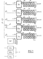
- Figures 1 to 3 show exemplary embodiments of such systems.
- the SSM 1 subsystem comprises 1 to 5 identical sets E1 to E5.
- the set E 1 consists of an adapter device DA 1 which is responsible for the connection, to one or more hosts H 1 , ..., H n , of a set of at most 12 disk memories, namely the disk memories 101 to 112.
- the twelve memories are interconnected by means of the same link chain 1A.
- the system for connecting the disk memories to the link 1A is such that if one of them is disconnected, all of the others continue to operate.
- the sets E 2 to E 5 have a structure identical to the set E 1 .
- the assembly E 2 consists of an adapter device DA 2 is of 12 disk memories 201 to 212 connected to the same link chain 2A. It is the same for the other sets E 3 to E 5 , the latter being composed of an adapter device DA 5 associated with 12 disk memories 601 to 612 connected to the same chain 5A.
- two identical electrical supplies AL 1 and AL 2 are associated with the SSM 1 subsystem, as well as a backup battery BAT 1 . This means that if one of the two power supplies AL 1 and AL 2 breaks down, the other replaces it, or that if the mains supply is interrupted, it is the battery BAT 1 which continues to ensure the electrical supply of each of the subassemblies E 1 to E 5 for a determined and programmable time.
- SSM 1 includes a fast writing processor FWP, which permanently monitors the operating state of AL 1 , AL 2 , BAT and authorizes or not, depending on this state, the "fast writing" mode or the normal writing mode.
- FWP fast writing processor
- FIG. 2 shows a second mass storage subsystem SSM 2 of standard RAID type.
- This system comprises a first CT 1 controller connected at least to a first central host H 1 (to hosts H 1 , ..., H n ) and a second CT 2 controller connected at least to a central host H 2 (to hosts H 1 , ..., H n ).
- the CT 1 controller can also be connected by an RS232 type link to a maintenance / configuration console or a modem, while the second CT 2 controller is connected by an RS 232 link of the same type as the previous one to a console maintenance / configuration or modem.
- the RS232 type link is normalized.
- Each of the two controllers CT 1 and CT 2 is connected to five sets E 1 to E 5 strictly identical to the sets E 1 to E 5 of FIG. 1.
- the SSM 2 system is redundant, which means that in the event of a failure of one of the two controllers, the second supports the entire load of the subsystem.
- the SSM 2 subsystem comprises two electrical supplies AL 1 and AL 2 , as well as a backup battery BAT 1 . It can therefore be seen that the SSM 2 subsystem is a secure and reliable system due to the redundancy, the doubling of the power supplies, and the possibility of changing (thanks to the RAID function), any of the disk memories of any one of the sets E 1 to E 5 without interrupting the operation of the others. It is also said that the SSM 2 subsystem has full availability.
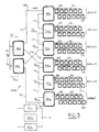
- FIG. 3 shows a third example of a mass storage RAID subsystem, namely SSM 3 , the new structure of which is proposed by the applicant.
- This subsystem comprises two host adapters HA 1 and HA 2 , connected to two (or more H 1 , ..., H n ) central hosts H 1 and H 2 , whose role is to manage the exchange of data between the one or the other of the two central hosts H 1 and H 2 and all of the adapter devices of the subsystem.
- Each of these host adapters is connected in the following manner to six sub-assemblies E 1 to E 6 which are completely identical in their mechanical structure to the assemblies with the same denomination in FIGS. 1 and 2.
- the first set E 1 consists of the adapter device DA 1 associated with the disk memories 101 to 112 connected to the link chain 1A, and so on up to the assembly E6 composed of the adapter device DA 6 associated with the disk memories 601 to 612 connected to the link chain 6A.
- the structure which connects the host adapters HA 1 and HA 2 to the six subsets E 1 to E 6 is a ring structure. This ring is designated by AN.
- the first host adapter HA 1 is connected on the one hand via the link L 1 to the device DA 1 of the assembly E 1 .
- DA 1 is connected by the link L 2 to DA 2 , which is connected by the link L 3 to the adapter device DA 3 itself connected by the link L 5 to the second host adapter HA 2 .
- the first host adapter HA 1 is also connected by the link L 4 to the adapter device DA 4 of the assembly EA 4 .
- DA 4 is itself connected by the link L 6 to the adapter device DA 5 which is itself connected by the link L 7 to the adapter device DA 6 of the assembly EA 6 .
- This latter adapter device is connected by the link L 8 to the second host adapter HA 2 .
- a ring structure AN is made, connecting the two host adapters HA 1 and HA 2 to the various adapter devices DA 1 to DA 6 .
- the SSM 3 subsystem includes two electrical supplies AL 1 and AL 2 , associated with a backup battery BAT 1 .
- the SSM 3 subsystem has the same advantages as the SSM 2 subsystem in terms of data availability and security. It is however much more efficient and scalable.
- the present invention relates to an extremely physical structure compact in the form of a drawer comprising several plates, capable of contain any of the three subsystems shown in Figures 1 to 3, with the possibility of switching from one type of system to another, for a same drawer on the same site where it is located (this property is known to those skilled in the art, under the Anglo-Saxon term of "upgradability"). To do this, simply change a background of basket in the drawer. Furthermore, this physical structure allows very high availability of the mass memory subsystem, thanks to the reduced number of elements, the non-propagation of breakdowns, the redundancy. In addition, any unit can be replaced at discs without interrupting the operation of the subsystem (when is in RAID, SSM2, SSM3 mode) and most can be changed elements of the assembly in operation without stopping it (non-stop operation).
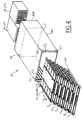
- the physical structure SP comprises, as can be seen see on these same figures, a drawer T of parallelepiped shape comprising on each of its side walls, a plurality of slides longitudinal parallel to each other and arranged one at the above the others, namely the pair of slides G1-G'1, G2-G'2, and so on until G7-G'7.
- the structure SP furthermore comprises a plurality of plates P1, P2, ..., P7, parallel to each other, relatively flat (of the order of 35 mm thick each) of rectangular parallelepiped shape which can each slide at inside of drawer T on slides G1-G'1 to G7-G'7.
- the plate P1 can slide inside the drawer T on the slides G1-G'1 and so on, up to the plate P7 which can slide on the slides G7-G'7. This way of inserting the plates inside the drawer T is extremely practical and allows any of them to be removed or inserted at will, with great ease of handling.
- any of the plates P 1 to P 7 can be inserted inside the drawer T by sliding the plate in question from front to back or from back to front, longitudinally, depending on the direction of the arrow f1 parallel to the length of the drawer T.
- the plates P 1 to P 7 are introduced through the front part of the drawer T, namely, TAV, while the rear part PAR consists of two supplies AL 1 and AL 2 each provided with a ventilation device V 1 , V 2 . These two absolutely identical power supplies are placed side by side in this rear part. They each have the shape of a rectangular parallelepiped block.
- Each of the plates P 1 to P 5 (or P 2 to P 6 ) carries a plurality of disk units, which can be a maximum of either 12 or 10 (among the two types of plates shown respectively in Figures 5 and 6 the first carries 12 disks and the second carries only 10 disks), that is to say 8 in the case of 3 and a half (3 "1 ⁇ 2) disks.
- P 1 carries disk drives
- P 6 carries either the FCP processor ( SSM 1 ) or CT 1 -CT 2 (SSM 2 ) and vice versa, so we will assume later that P 1 carries disk drives.
- Plate P 7 carries a set of BAT backup batteries.
- the front part PAV and the rear part PAR are separated by a bottom of FP basket which carries a certain number of electrical connections and of which the surface is limited to let the ventilation air (this surface is much less than the area of the rectangular cross section of T).
- FIG 11 also in its part 11a than in its part 11b shows more in detail the ventilation system arranged on the rear part of the block this ventilation unit being composed of a fan with five blades.
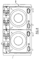
- the rear face FAR of the PAR part which can be seen in FIG. 8 further comprises two switches I 1 and I 2 intended respectively for starting up each of the power supply units AL 1 and AL 2 and two mains sockets SECT 1 and SECT 2 each arranged in the right part of each of the two power supplies.
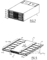
- FIG. 5 P 1 carries 12 disk memories 101 to 112, whereas in FIG. 6, this same plate only has 10 disk memories 101 to 110.
- the plate P 1 therefore comprises two parallel rows of six disk memories ( Figure 5) or 5 disk memories ( Figure 6), namely respectively a first row of disk memories 101 to 106 (101 to 105) and a second row of disk memories 107 to 112 (106 110).
- Figure 5 Figure 5
- Figure 6 Figure 6
- these different disk memories are arranged side by side, their longitudinal axes being perpendicular to the longitudinal axis of the plates P 1 .
- the plate P 1 comprises a central part carrying the electronic card CDA1 carrying an adapter device DA 1 , which may be any of the adapter devices shown in Figures 1 to 3.
- the two rows of discs 101 to 106, 107 to 112 (101 105, 106 to 110) are arranged on either side of this central part CDA 1 .
- the disk units (we will use hereinafter, for simplicity, the expression “disk” in place of “disk units”) of the first row are all connected, in a manner which will be indicated later, on one side of the CDA plate 1 .
- This plate is rectangular in size and its longitudinal direction is the same as the longitudinal direction of the drawer T.
- the discs of the second row are connected to the CDA plate 1 on the same side of the CDA 1 card, opposite side to the one to which the disks in the first row are connected.
- the plate P 1 comprises on its front part two grips PPR 1 and PPR 2 allowing any human operator to insert or extract more easily the plate in question inside the drawer T.
- the first handle namely PPR 1 is on the side of the row of discs 101 to 106, on the side of the left longitudinal edge of the plate P 1 , in FIG. 5, while the second handle PPR 2 is on the side of the second row of discs 107 to 112, next to the longitudinal edge of the plate P 1 located on the right part of FIG. 5.
- the levers EX 101 to EX 105 are associated respectively with the discs 101 to 105, while the levers EX 107 to EX 112 are respectively associated with the discs 107 to 112. It is quite obvious that it would be the same for the non visible levers in FIGS. 5 and 6, namely the levers EX 101 to EX 106 on the one hand, and EX 106 to EX 110 on the other hand, respectively associated with memories 101 to 106 and 106 to 110.
- the manner in which we proceed to insert (or extract) the discs in the (de) plate P 1 and lock them so as to connect them to the CDA plate 1 will be explained later, in relation to FIGS. 12 to 14.
- FIGS. 5 and 6 one can see in the center of the plate, respectively on the front edge and on the rear edge of the latter (those which are respectively visible in these same figures) a series VAT and a series TVR of holes ventilation, rectangular allowing the passage of ventilation air V in the direction indicated by the arrows, these arrows being parallel to the length of the plate P 1 , that is to say to the length of the drawer T
- the ventilation air V sucked in by fans V 1 and V 2 therefore flows back and forth in the direction of the length of the plates. It passes above and below the discs 101 to 106 and 107 to 112 (101 to 105, 106 to 110).
- the memories 101 to 105 are shown inserted in the plate P 1 while the memories 106 to 110 are shown not inserted outside of P 1 on the right part of the figure.
- the levers EX 106 to EX 110 have been shown in the position they occupy once the memories 106 to 110 have been extracted from the plate P 1 .
- this position which can be called the extraction position, each of the levers in question makes a determined angle with the longitudinal edge of the plate, an angle close to 30 ° in FIG. 9.
- levers can therefore perform a rotation equal to this angle, from a position where they are pressed against the edge of the plate to the extraction position thanks to a hinge not shown around which they can pivot, this hinge being perpendicular to the plane of the plate P 1 . (i.e. vertical in Figure 9.)
- FIG. 9 there is shown partially detached from the plate P 1 , the electronic card CDA 1 , the latter being arranged on a support SP 1 . It can slide on it from front to back or vice versa when you want to remove it or insert it.
- This support comprises in its rear part a PE 1 extraction handle making it possible to remove it from the central part of the plate P 1 . (This, for example takes place before removing the CDA 1 electronic card, when it is necessary for example to change it).
- This CDA card 1 is inserted under the cover CP 1 placed in the upper part of the plate in FIG. 9, in the center of the plate.
- CDA 1 comprises on each of its two longitudinal edges, a plurality of connectors, namely the connectors C 101 to C 105 on the left longitudinal edge and C 106 to C 110 on the right longitudinal edge. It is obvious that the CDA card 1 could contain twice six connectors, namely C 101 to C 106 on its left edge and C 107 to C 112 on its right edge if the plate P 1 contains 12 disks in place of the 10 drives shown in figure 9. All connectors C 101 to C 110 are identical and correspond to the standard used for the operation of the drives, here the SCSI standard.
- the various connectors are regularly spaced.
- said card comprises a rear connector, CAR 1 which makes it possible to connect it, through connections arranged in the rear part PAR of drawer T, at least one external host system. This will be illustrated more particularly in the subsequent description in relation to FIG. 16.
- Figure 12 shows how a disk D is fixed on its SD support.
- the disc D can be any one of the discs 101 to 112, 201 to 212, etc., of any of the systems shown in Figures 1 to 3.
- This disc is therefore provided with 4 feet arranged on its part lower (see figure 12b) FO 1 to FO 4 , only the first two being visible in figure 12b.
- the disc also includes a CN connector intended to be inserted into the associated connectors of the corresponding electronic card. We can therefore say that each of the disks 101 to 112, 101 to 110 has a connector CN 101 to CN 112 (CN 101 to CN 110 ).
- connectors CN 101 to CN 112 for example are intended to be connected to the corresponding connector C 101 to C 112 (C 101 to C 110 ) of the plate P 1 .
- Each of the CN type connectors is of course compliant with the SCSI standard. If we consider Figure 12a which shows the support of the SD disk, we see that it includes 4 shoulders EP 1 , EP 2 , EP 3 , EP 4 arranged on each of the two longitudinal edges of the support, with of course two shoulders on each edge. Each of these two shoulders is associated with a foot of the disc intended to be inserted on the support. The shoulder EP1 is therefore associated with the foot FO 1 , the shoulder EP 2 with the foot FO 2 , etc.
- Each of the shoulders includes in its center a hole through which a screw can be passed which will be inserted into the foot corresponding allowing the fixing of the disk D on its support.
- these screws are not shown in FIG. 12.
- the front of the SD support, located on the right part in FIG. 12a includes an opening O inside which is inserted the connector CN when disk D is mounted on the support.
- the front part of the DAV disc is therefore that which comes into contact with the central part of the plate P 1 .
- the rear part of the disc here designated by DAR, has the shape of an inverted L-shaped angle which allows an extremely easy manual gripping of the support for the operations of handling it. DAR is located on the left side of Figure 12a.
- the SD support comprises, on the rear side, a groove R whose axis is parallel to the longitudinal axis of the plate P 1 when the corresponding disc is mounted on the plate (the axis of R is in fact perpendicular to the length of SD).
- This groove comprises two parts, a part R 1 and a part R 2 , the part R 1 having a rectangular shape ending in a semicircle, having a width I (I being measured parallel to the length of the support SD) and the part R 2 adjoining part R 1 , having a circular shape with a diameter greater than l.
- the functional utility of the division into two parts of the groove R will appear better in connection with the description of Figures 13 and 14.
- FIG. 12c we see seen from 3/4 in perspective, the disk D mounted on its support, the foot FO 1 being screwed on the shoulder EP 1 , the foot FO 2 on the shoulder EP 2 , the connector CN being disposed inside the opening O.
- a handle PO which is mounted by screwing on the part before DAR. This handle PO allows manual manipulation with ease of the disk D when it is mounted on its support in order for example to insert it into the plate (for example P 1 ) where it is mounted. If we consider Figure 12d, we can see the shoulders EP 3 and EP 4 on which the handles PO 3 and PO 4 are screwed.
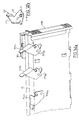
- any of the extraction levers here called EX this extraction lever can for example be any of the levers EX 105 , EX 104 , EX 103 , etc ... shown in Figures 14a and 13.
- EX the extraction lever
- this vertical part EV is that which the manual operator manipulates.
- the horizontal part EH is mounted on the cover CP 1 of the plate P 1 .
- the extraction lever EX further comprises fixed on its horizontal part EH a stud TET comprising an upper part TS and a cylindrical lower part TI.
- the latter has a diameter equal to the width I of the part R1 of the groove R in which it is inserted.
- the upper part TS has a diameter which is very slightly less than the diameter of the part T 2 of the groove R, so as to be able be introduced into it.
- the disc for example disc 105 (as visible on the right part of figure 13) by its front part DAV in such a way that by sliding it towards the electronic card CDA 1 , this front part comes into contact with the connector of the corresponding card, here for example, the connector C 105 .
- the disc 105 is inclined relative to the plane of the plate P 1 .
- the connector CN 105 of the disc 105 comes into contact with the connector C 105 , the disc can be folded down so that its support SD is placed flat on the plate P 1 . In this case, the disc occupies the position indicated in the center of FIG.
- the TET pin slides in the groove so as to pass from the part R2 thereof to the part R 1 and more precisely come into contact with the end thereof. semicircle shape (see also Figure 12a).
- the disc here 103 is locked and connected to the corresponding connector C 103 (see left part of FIG. 13).
- the PAV part and the rear part PAR of the drawer T are separated by a backplane FP which comprises a plurality of connection means (which will be more detailed in FIG. 16) making it possible to connect each of the plates P 1 to central hosts located outside the drawer T.
- the backplane FP comprises a plurality of connection links between the various plates which make it possible to produce one or the other of the structures of mass memory subsystems SSM 1 to SSM 3 which are represented in FIGS. 1 to 3. It therefore suffices to change the backplane FP to pass from one of the structures to the other, without changing in any way the constitution of the plates P 1 to P 5 or P 6 .
- the drawer T as designed allows to accommodate a large variety of mass memory subsystems, being able to switch from one to the other easily on the site itself where the T-shaped drawer is arranged. It is said in Anglo-Saxon language that we are dealing with an "up-gradable" system.
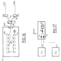
- FIG. 16 shows how the plate P 1 is connected to two host systems H 1 and H 2 .
- This figure shows the disks 101 to 112 which are connected together by a SCSI link of the standard "Single ended" type.
- This link is here called LSE 1 .
- LSE 1 the SCSI type links are in differential mode. It is therefore necessary to have in the subsystem, and for each plate, a CV 1 converter (CV 2 , ising, CV 6 ) making it possible to ensure the transition between the link in "single- ended "LSE 1 and external connections in differential mode.
- these links are L 11 and L 12 respectively making it possible to connect the disks of P 1 via CV 1 on the one hand to a connector CX 1 connected to a first central host H1 and on the other hand to a connector CX2 itself connected to a second central host H2.
- the CX1 and CX2 connectors are standardized, as are the L 11 and L 12 connections .
- CV 1 is connected to the plate P 1 via LSE 1 and the connector CAR 1 .
- the bottom FP comprises a plurality of connectors CAR 1 , CAR 2 , etc. Furthermore, by referring to FIG.
- FIG. 8 which shows the rear face FAR of the drawer T, we can see on the upper left part of this same figure the two connectors CX 1 and CX 2 .
- the rear face FAR also includes all the connectors of the other plates P 2 to P 5 or P 6 . There is therefore room for 12 connectors in Figure 8.
- the drawer T comprises two identical power supplies AL 1 and AL 2 which are connected, for each plate of type P 1 to respectively two diodes D 1 and D 2 itself connected to a fuse F 1 itself connected to a CVE 1 electrical converter.
- the two power supplies AL 1 deliver a DC voltage of 48 volts, while the converter CVE 1 delivers a voltage of + 5 volts. It therefore ensures the conversion from 48 to 5 volts.
- the fuse F 1 provides protection for the plate P 1 . Since it is the same for each of the plates, it is seen that only one of them can be affected by an overvoltage or an overcurrent, the others being able to continue to function. It therefore suffices to change the fuse such as F 1 , of the plate in question to restart the plate affected by this incident. Furthermore, all the plates P 1 to P 6 can be removed without the need to cut off the electrical supply to the other plates, the converter CVE1 being equipped with an inhibition input INHIB controlled by a switch manually operated by the operator , (this for each of the plates P1 to P6) and located on the front part of the drawer T.
Landscapes
- Engineering & Computer Science (AREA)
- Microelectronics & Electronic Packaging (AREA)
- Casings For Electric Apparatus (AREA)
- Power Sources (AREA)
- Mounting Of Printed Circuit Boards And The Like (AREA)
- Coupling Device And Connection With Printed Circuit (AREA)
Description
- une pluralité de groupement d'unités à disques amovibles disposée à l'intérieur de la structure dans une pluralité de compartiments recevant chacun au moins une unité,
- au moins une alimentation électrique des unités,
- une partie avant comportant un ensemble de plaques parallèles les unes aux autres, pouvant coulisser à l'intérieur des compartiments et porter une pluralité d'unités à disques disposées cote à côte de part et d'autre d'une partie centrale portant une carte électronique d'adaptateurs à laquelle elles sont connectées, assurant soit la gestion en temps réel des unités à disques de la plaque, soit simplement leur connexion vers les systèmes hôtes,
- une partie arrière comportant notamment l'alimentation électrique de toutes les unités à disques,
- un fond de panier connecté d'une part à chacune des cartes et d'autre par au système hôte par l'intermédiaire de moyens de connexion disposés dans la partie arrière, le dessin des connexions réalisé sur le fond de panier permettant de donner au sous-système une configuration déterminée.
- Les figures 1 à 3 montrent 3 exemples de sous-systèmes de mémoire de masse pouvant être contenus dans la structure physique selon l'invention,
- La figure 4 est une vue de 3/4 en perspective montrant les différentes parties constitutives essentielles de la structure physique selon l'invention, à savoir ensemble de plaques, tiroirs et alimentations électriques,
- La figure 5 est une vue de 3/4 en perspective, vue de l'avant d'un premier modèle de plaque porteuse d'une pluralité d'unités à disques,
- La figure 6 est une vue de 3/4 prise de l'arrière, d'un second modèle de plaque porteuse d'unités à disques,
- La figure 7 est une vue de 3/4 en perspective du tiroir dans son ensemble, les plaques étant disposées à l'intérieur de celui-ci,
- La figure 8 est une vue de face de la partie arrière de la structure physique selon l'invention,
- La figure 9 montre, de façon détaillée, vue de 3/4 en perspective depuis l'avant, la plaque de la figure 6, montrant plus en détail les différentes parties constitutives de celle-ci,
- La figure 10 montre vue de 3/4 en perspective une carte électronique portant un dispositif adaptateur pouvant être connecté à une pluralité d'unités à disques appartenant à la plaque,
- La figure 11, composée des figures 11A et 11B montre, plus en détail, un bloc d'alimentation électrique de la structure physique selon l'invention,
- La figures 12, composée des figures 12a à 12d montre comment une unité à disques est montée sur son support,
- La figure 13 montre comment des unités à disques sont insérées à l'intérieur d'une plaque puis connectées sur la carte d'adaptateur appartenant à cette dernière,
- La figure 14 composée des figures 14a et 14b montre plus en détail le mécanisme qui permet d'insérer une unité à disques à l'intérieur d'une plaque,
- La figure 15 est une vue de côté en coupe montrant l'ensemble de la structure physique selon l'invention, avec son fond de panier séparant les parties avant et arrière,
- La figure 16 montre comment une plaque déterminée est connectée à au moins un système hôte extérieur,
- La figure 17 montre le système d'alimentation électrique de l'une quelconque des plaques appartenant à la structure physique selon l'invention.
Claims (8)
- Structure physique (T) d'un sous-système de mémoire de masse (SSM1 à SSM3) reliée à au moins un système hôte (H1, H2) comprenant :caractérisée en ce qu'elle comprend :une pluralité de groupements d'unités à disques (101 à 112, 201 à 212,..., 601 à 612) disposés à l'intérieur de la structure, dans une pluralité de compartiments recevant chacun au moins une unité, etau moins une alimentation électrique des unités (AL1, AL2),une partie avant (PAV) comportant un ensemble de plaques parallèles les unes aux autres (P1 à P6), pouvant coulisser à l'intérieur des compartiments et porter une pluralité d'unités à disques disposées côte à côte de part et d'autre d'une partie centrale (CDA1) portant une carte électronique à laquelle elles sont connectées, cette dernière assurant soit la gestion en temps réel des unités à disques de la plaque, soit simplement leur connexion vers le système hôte.une partie arrière (PAR) comportant notamment l'alimentation électrique,un fond de panier (FP) connecté d'une part à chacune des cartes électroniques des plaques et d'autre part au système hôte (H1) par l'intermédiaire de moyens de connexion disposés dans la partie arrière (CAR, CX1, CX2) le dessin des connexions réalisé sur le fond de panier permettant de donner au sous-système une configuration déterminée (SSM1, SSM2, SSM3).
- Structure physique selon la revendication 1, caractérisée en ce que à l'intérieur d'une plaque, les unités à disques sont réparties en deux rangées parallèles l'une à l'autre, les différentes unités à disques constituant chaque rangée étant disposées côte à côte, leur axe longitudinal étant perpendiculaire à l'axe longitudinal de la plaque (101 à 106, d'une part, 107 à 112 d'autre part).
- Structure selon la revendication 2, caractérisée en ce que chaque unité à disques d'une rangée est munie de moyens de connexion (CN101 à CN106, CN107 à CN112) disposés du côté de la carte électronique, qui sont connectés à des moyens de connexion correspondants appartenant à la dite carte électronique, les moyens de connexion de celle-ci (C101 à C106, C107 à C112) étant fixés sur les côtés longitudinaux de la carte, en étant régulièrement espacés sur celle-ci.
- Structure physique selon l'une des revendications 2, 3, caractérisée en ce que la partie arrière (PAR) comporte des moyens de ventilation (V1, V2) montés à l'intérieur de l'alimentation électrique (AL1,AL2), permettant d'assurer la ventilation de celle-ci et de l'ensemble des plaques, chaque plaque comportant sur son bord avant disposé vers l'extérieur du tiroir (T) et sur son bord arrière disposé du côté du fond de panier (FP) des trous de ventilation régulièrement espacés (TVA, TVR) permettant le passage de l'air de ventilation dans un sens parallèle à la longueur de chaque plaque, cet air de ventilation (V) circulant d'avant en arrière dans un sens parallèle à la longueur des plaques.
- Structure selon l'une des revendications 2, 3 caractérisée en ce que chaque plaque (P1 à P6), comporte sur chacun de ses bords longitudinaux des leviers d'extraction et d'insertion de chaque unité à disques d'une rangée (EX101 à EX105, EX106 à EX110), pouvant occuper deux positions, une première position dite d'extraction (POS1) et une seconde position dite d'insertion (POS2), les leviers pouvant effectuer une rotation autour d'une charnière perpendiculaire au plan de la plaque, permettant de passer de la position d'extraction à la position d'insertion, l'unité à disques associée au levier étant soit extérieure à la plaque, soit non connectée à la carte électronique lorsque le levier est dans la première position, et étant connectée à cette même carte lorsque le levier est dans la seconde position.
- Structure selon la revendication 5, caractérisée en ce que chaque unité à disques est montée sur une support par l'intermédiaire de moyens de fixation, ceux-ci comprenant d'une part une pluralité de pieds (FO1 à FO4) disposés sur la partie inférieure du disque, et d'autre part des épaulements appartenant au support destinés à venir en contact avec les dits pieds, et des moyens de liaison entre les pieds et les épaulements, chaque support comportant dans sa partie avant une ouverture (O) à l'intérieur de laquelle vient s'insérer le connecteur (CN101 à CN110 ou CN112) du disque quant ce dernier est monté sur son support.
- Structure selon la revendication 6, caractérisée en ce que le support (SD) comprend du côté de sa partie arrière, une rainure (R) dont l'axe est parallèle à l'axe longitudinal de la plaque (P1 à P6) quand l'unité à disque correspondante est montée sur celle-ci, la rainure comprenant une première partie (R1) et une seconde partie (R2) contiguës, la première ayant une forme rectangulaire terminée par un demi-cercle de largeur donnée (I) et la seconde ayant une forme circulaire de diamètre supérieur à (I).
- Structure selon la revendication 7, caractérisée en ce que chaque levier d'extraction et d'insertion (EX101 à EX112) comprend une partie verticale (EV) et une partie horizontale (EH), la partie verticale (EV) étant manipulée par un opérateur, alors que la partie horizontale (EH), comprend un téton (TET) pouvant être introduit dans la seconde partie (R2) de la rainure (R) et pouvant coulisser parallèlement à l'axe de cette rainure (R) de telle façon qu'en passant de la position où il est à l'intérieur de la seconde partie (R2) à la position où il est à l'intérieur du demi-cercle de la première partie (R1), le levier d'extraction correspondant passe de la première position d'extraction (POS1) à la position d'insertion (POS2).
Applications Claiming Priority (2)
| Application Number | Priority Date | Filing Date | Title |
|---|---|---|---|
| FR9304772A FR2704350B1 (fr) | 1993-04-22 | 1993-04-22 | Structure physique d'un sous système de mémoire de masse. |
| FR9304772 | 1993-04-22 |
Publications (2)
| Publication Number | Publication Date |
|---|---|
| EP0621600A1 EP0621600A1 (fr) | 1994-10-26 |
| EP0621600B1 true EP0621600B1 (fr) | 1998-07-08 |
Family
ID=9446338
Family Applications (1)
| Application Number | Title | Priority Date | Filing Date |
|---|---|---|---|
| EP94400797A Expired - Lifetime EP0621600B1 (fr) | 1993-04-22 | 1994-04-13 | Structure physique d'un sous-système de mémoire de masse |
Country Status (5)
| Country | Link |
|---|---|
| US (1) | US5506750A (fr) |
| EP (1) | EP0621600B1 (fr) |
| JP (1) | JP2571907B2 (fr) |
| DE (1) | DE69411441T2 (fr) |
| FR (1) | FR2704350B1 (fr) |
Families Citing this family (68)
| Publication number | Priority date | Publication date | Assignee | Title |
|---|---|---|---|---|
| FR2738659B1 (fr) * | 1995-09-08 | 1997-10-24 | Bull Sa | Dispositif d'habillage d'unite a disques pour systeme multidisques |
| FR2771225B1 (fr) * | 1997-11-20 | 1999-12-24 | Bull Sa | Protection contre les defauts electriques dans un systeme de stockage de donnees |
| US6625144B1 (en) * | 1998-08-18 | 2003-09-23 | International Business Machines Corporation | Dual-use DB9 connector for RS-232 or dual-active controller communication |
| US6154361A (en) * | 1998-10-02 | 2000-11-28 | International Business Machines Corporation | Disk-drive chassis for reducing transmission of vibrations between disk-drive units of a disk-drive array |
| WO2000028545A1 (fr) * | 1998-11-09 | 2000-05-18 | Sony Corporation | Ensemble de disques durs et appareil d'enregistrement/lecture |
| WO2000028546A1 (fr) * | 1998-11-10 | 2000-05-18 | Sony Corporation | Appareil d'enregistrement / reproduction de donnees |
| EP1931137B1 (fr) | 2001-04-12 | 2012-12-12 | Sony Corporation | Appareil de traitement de signal, étagère de stockage et appareil de connexion |
| US6563704B2 (en) * | 2001-06-15 | 2003-05-13 | Sun Microsystems, Inc. | Storage device arrangement for increased cooling |
| US6618249B2 (en) * | 2002-02-05 | 2003-09-09 | Quantum Corporation | Thermal cooling system for densely packed storage devices |
| US20030209945A1 (en) * | 2002-05-07 | 2003-11-13 | Hanson George E. | Cross ventilation technique for cooling redundant power supplies |
| US6975509B2 (en) * | 2002-05-16 | 2005-12-13 | Sun Microsystems, Inc. | Computing apparatus with cooling fan |
| JP4312424B2 (ja) | 2002-06-14 | 2009-08-12 | 株式会社日立製作所 | ディスクアレイ装置 |
| US6862173B1 (en) | 2002-07-11 | 2005-03-01 | Storage Technology Corporation | Modular multiple disk drive apparatus |
| US6925531B2 (en) * | 2002-07-11 | 2005-08-02 | Storage Technology Corporation | Multi-element storage array |
| US6754082B1 (en) * | 2002-11-07 | 2004-06-22 | Exavio, Inc. | Data storage system |
| US6853548B2 (en) * | 2003-01-02 | 2005-02-08 | Quantum Corporation | 1U rack mount equipment enclosure with increased structural support |
| US7304855B1 (en) | 2003-03-03 | 2007-12-04 | Storage Technology Corporation | Canister-based storage system |
| JP4260554B2 (ja) * | 2003-06-17 | 2009-04-30 | 株式会社日立製作所 | ストレージ装置用筐体、及びストレージ装置 |
| US7038915B2 (en) * | 2003-08-05 | 2006-05-02 | International Business Machines Corporation | Apparatus, system, and method for arraying electrical devices in a cabinet |
| US6987674B2 (en) * | 2003-09-12 | 2006-01-17 | Lsi Logic Corporation | Disk storage system with removable arrays of disk drives |
| US7042717B2 (en) * | 2003-09-12 | 2006-05-09 | Lsi Logic Corporation | Data storage system with a removable backplane having a array of disk drives |
| US7145770B1 (en) * | 2003-10-08 | 2006-12-05 | Copan Systems, Inc. | Method and apparatus of packaging disk drives in a data storage system |
| US7167359B2 (en) * | 2003-12-29 | 2007-01-23 | Sherwood Information Partners, Inc. | System and method for mass storage using multiple-hard-disk-drive enclosure |
| JP4105121B2 (ja) * | 2004-05-14 | 2008-06-25 | 富士通株式会社 | 電子機器の筐体構造、及びディスクアレイ装置 |
| EP1662369B1 (fr) * | 2004-11-30 | 2017-12-06 | Fujitsu Limited | Système de stockage de données et appareil de commande pour une mémoire de données |
| JP4621039B2 (ja) | 2005-02-22 | 2011-01-26 | 株式会社日立製作所 | ディスク装置 |
| US7486526B1 (en) * | 2005-03-29 | 2009-02-03 | Emc Corporation | Techniques for redundant computing from within a 1U form factor with improved serviceability and high availability characteristics |
| US7312999B1 (en) * | 2005-04-29 | 2007-12-25 | Network Appliance, Inc. | High density drive chassis assembly |
| US8111514B2 (en) * | 2006-04-21 | 2012-02-07 | Maxvision Corporation | Removable hard drive module for a computer with improved thermal performance |
| US7542295B2 (en) * | 2006-04-21 | 2009-06-02 | Maxvision Corporation | Removable hard drive module for a computer |
| US8385061B2 (en) | 2006-10-24 | 2013-02-26 | Lsi Corporation | System and method for implementing a meta-disk aggregation model for storage controllers |
| US7844770B2 (en) * | 2006-11-02 | 2010-11-30 | Bretford Manufacturing, Inc. | Hub structure for enabling communication with a large number of handheld electronic devices |
| US7881062B2 (en) * | 2007-07-09 | 2011-02-01 | Mitac International Corp. | Extension bracket module |
| US7864539B2 (en) * | 2008-04-11 | 2011-01-04 | Lsi Corporation | Horizontal drive drawer system and method |
| US9426903B1 (en) | 2008-06-27 | 2016-08-23 | Amazon Technologies, Inc. | Cooling air stack for computer equipment |
| US9894808B2 (en) | 2010-03-31 | 2018-02-13 | Amazon Technologies, Inc. | Compressed air cooling system for data center |
| US9622387B1 (en) | 2010-03-31 | 2017-04-11 | Amazon Technologies, Inc. | Rack-mounted air directing device with scoop |
| US8755192B1 (en) | 2010-03-31 | 2014-06-17 | Amazon Technologies, Inc. | Rack-mounted computer system with shock-absorbing chassis |
| US8638553B1 (en) | 2010-03-31 | 2014-01-28 | Amazon Technologies, Inc. | Rack system cooling with inclined computing devices |
| US10492331B1 (en) | 2010-09-29 | 2019-11-26 | Amazon Technologies, Inc. | System and method for cooling power distribution units |
| US8743549B2 (en) | 2011-03-22 | 2014-06-03 | Amazon Technologies, Inc. | Modular mass storage system |
| GB201107860D0 (en) | 2011-05-11 | 2011-06-22 | Manda Ion | Rack module |
| US9019708B2 (en) * | 2011-08-25 | 2015-04-28 | Lsi Corporation | Apparatus and systems having storage devices in a side accessible drive sled |
| US10082857B1 (en) | 2012-08-07 | 2018-09-25 | Amazon Technologies, Inc. | Cooling electrical systems based on power measurements |
| US9330729B2 (en) * | 2012-09-24 | 2016-05-03 | International Business Machines Corporation | Slim profile, rear docking tape drive canister |
| US9894809B1 (en) | 2013-02-28 | 2018-02-13 | Amazon Technologies, Inc. | System for supplying cooling air from sub-floor space |
| USD724081S1 (en) | 2013-03-05 | 2015-03-10 | Hewlett-Packard Development Company, L.P. | Top loading fan cartridge |
| US10178807B2 (en) | 2013-03-26 | 2019-01-08 | Hewlett Packard Enterprise Development Lp | Top loading cartridge |
| EP2979148A4 (fr) | 2013-03-26 | 2017-03-08 | Hewlett-Packard Enterprise Development LP | Cartouche à chargement par le haut |
| US9736961B2 (en) | 2013-03-26 | 2017-08-15 | Hewlett Packard Enterprise Development Lp | Top loading cartridge |
| US9326415B2 (en) * | 2013-09-14 | 2016-04-26 | Seagate Technology Llc | Chassis for storage devices |
| US9232677B2 (en) * | 2013-09-14 | 2016-01-05 | Seagate Technology Llc | Chassis for storage devices |
| TW201531205A (zh) * | 2014-01-22 | 2015-08-01 | Quanta Comp Inc | 伺服器裝置 |
| US10398060B1 (en) * | 2014-03-17 | 2019-08-27 | Amazon Technologies, Inc. | Discrete cooling module |
| US10548237B2 (en) * | 2015-02-20 | 2020-01-28 | Hewlett Packard Enterprise Development Lp | Externally accessible replaceable power source |
| US9763353B1 (en) | 2015-03-23 | 2017-09-12 | Amazon Technologies, Inc. | Mass storage device retainer assembly |
| US9629275B1 (en) | 2015-03-25 | 2017-04-18 | Amazon Technologies, Inc. | Mass storage device retainer assembly |
| TWI590741B (zh) * | 2015-04-16 | 2017-07-01 | 緯創資通股份有限公司 | 可裝載多個儲存單元的儲存單元結合模組、及可裝載多個儲存單元結合模組的儲存單元移動套件與其相關的伺服器設備 |
| US10025357B2 (en) * | 2015-06-15 | 2018-07-17 | Seagate Technology Llc | Enclosure system for computing equipment |
| US10191520B2 (en) * | 2015-07-22 | 2019-01-29 | Celestica Technology Consultancy (Shanghai) Co. Ltd | Electronic apparatus having function of switching node modules |
| CN105676971B (zh) * | 2015-07-22 | 2021-03-23 | 加弘科技咨询(上海)有限公司 | 电子装置 |
| US10212846B2 (en) * | 2016-05-12 | 2019-02-19 | Facebook, Inc. | Data storage server drawer |
| US10776298B2 (en) | 2016-12-22 | 2020-09-15 | Seagate Technology, Llc | Multi-device data storage module |
| US20190068466A1 (en) * | 2017-08-30 | 2019-02-28 | Intel Corporation | Technologies for auto-discovery of fault domains |
| WO2021163205A1 (fr) * | 2020-02-11 | 2021-08-19 | Schneider Electric It Corporation | Module électrique de base pour centre de données modulaire |
| US11531383B1 (en) | 2020-09-30 | 2022-12-20 | Amazon Technologies, Inc. | Mist cooling for computer systems |
| JP7775612B2 (ja) * | 2021-09-28 | 2025-11-26 | セイコーエプソン株式会社 | 印刷装置、及び印刷装置の生産方法 |
| US12382607B1 (en) | 2023-05-02 | 2025-08-05 | Amazon Technologies, Inc. | Liquid immersion chassis liner |
Family Cites Families (6)
| Publication number | Priority date | Publication date | Assignee | Title |
|---|---|---|---|---|
| US4833554A (en) * | 1987-02-25 | 1989-05-23 | Tandon Corporation | Hard disk drive module and receptacle therefor |
| EP0356977B1 (fr) * | 1988-09-01 | 1994-01-05 | Fujitsu Limited | Dispositif à disque rotatif |
| US5173819A (en) * | 1988-10-05 | 1992-12-22 | Hitachi, Ltd. | Disk apparatus having an improved cooling structure |
| FR2652940B1 (fr) * | 1989-10-05 | 1994-03-11 | Bull Sa | Dispositif de fixation de peripheriques d'ordinateur. |
| GB2241118A (en) * | 1990-02-15 | 1991-08-21 | Ibm | Electrical apparatus with forced air cooling |
| EP0488679A3 (en) * | 1990-11-30 | 1993-08-04 | Fujitsu Limited | Storage disk module and storage disk device having a plurality of storage disk modules |
-
1993
- 1993-04-22 FR FR9304772A patent/FR2704350B1/fr not_active Expired - Fee Related
-
1994
- 1994-04-13 EP EP94400797A patent/EP0621600B1/fr not_active Expired - Lifetime
- 1994-04-13 DE DE69411441T patent/DE69411441T2/de not_active Expired - Lifetime
- 1994-04-21 JP JP6083428A patent/JP2571907B2/ja not_active Expired - Lifetime
- 1994-04-22 US US08/231,103 patent/US5506750A/en not_active Expired - Lifetime
Also Published As
| Publication number | Publication date |
|---|---|
| DE69411441D1 (de) | 1998-08-13 |
| JP2571907B2 (ja) | 1997-01-16 |
| FR2704350B1 (fr) | 1995-06-02 |
| FR2704350A1 (fr) | 1994-10-28 |
| JPH076004A (ja) | 1995-01-10 |
| EP0621600A1 (fr) | 1994-10-26 |
| US5506750A (en) | 1996-04-09 |
| DE69411441T2 (de) | 1998-12-03 |
Similar Documents
| Publication | Publication Date | Title |
|---|---|---|
| EP0621600A1 (fr) | Structure physique d'un sous-système de mémoire de masse | |
| EP0515342B1 (fr) | Coffret pour au moins un disque à haute densité d'information | |
| EP0981797B1 (fr) | Connecteur electrique pour le raccordement simultane de plusieurs cartes a circuit(s) integres(s) a contact | |
| CA2024510A1 (fr) | Terminal informatique portatif a ecran pivotant | |
| FR2610132A1 (fr) | Appareil multi-disques de lecture des enregistrements portes par les disques | |
| WO2006007467A2 (fr) | Enceinte de lecteurs a profondeurs multiples | |
| FR2676566A1 (fr) | Connecteur pour carte a circuits. | |
| FR2816747A3 (fr) | Appareil d'ejection automatique de disque, et ensemble d'arrangement de disques pour ordinateurs | |
| EP0541503B1 (fr) | Dispositif de transfert pour supports d'informations | |
| EP0394098A1 (fr) | Dispositif pour branchement d'un disque dur amovible | |
| FR2480471A1 (fr) | Boitier a cassette perfectionne | |
| EP0416973A2 (fr) | Armoire de rangement pour objets nombreux de petites dimensions | |
| EP0762426B1 (fr) | Dispositif de montage d'unité à disques pour système multidisques | |
| EP0160992A2 (fr) | Mémoire à disques incluant une cartouche pour disque(s) magnétique(s) amovible(s) et cartouche incluse dans cette mémoire | |
| EP0285955B1 (fr) | Dispositif de couplage de memoires non volatiles dans une machine electronique et machine à affranchir en faisant application | |
| EP2764762B1 (fr) | Equipement informatique a introduire de maniere amovible dans une armoire informatique et a connecter a des dispositifs electroniques | |
| EP0025390A1 (fr) | Magasin débiteur de films destiné à équiper un changeur de films radiographiques, et changeur équipé d'un tel magasin | |
| EP0177529B1 (fr) | Lecteur pluri video-disques multi-faces | |
| FR2720032A1 (fr) | Reliure de feuilles. | |
| JP2000511137A (ja) | Cd保管モジュール | |
| Martel | L'anthropologie d'Althusser. | |
| FR2821973A1 (fr) | Dispostif de rangement pour supports d'enregistrement | |
| FR3155405A3 (fr) | Structure de châssis | |
| FR2747963A1 (fr) | Support d'etiquette d'identification et dossier suspendu comprenant un tel support | |
| EP1395990A1 (fr) | Conditionnement pour support d'informations en forme de disque |
Legal Events
| Date | Code | Title | Description |
|---|---|---|---|
| PUAI | Public reference made under article 153(3) epc to a published international application that has entered the european phase |
Free format text: ORIGINAL CODE: 0009012 |
|
| AK | Designated contracting states |
Kind code of ref document: A1 Designated state(s): DE ES FR GB IT |
|
| 17P | Request for examination filed |
Effective date: 19941114 |
|
| GRAG | Despatch of communication of intention to grant |
Free format text: ORIGINAL CODE: EPIDOS AGRA |
|
| GRAG | Despatch of communication of intention to grant |
Free format text: ORIGINAL CODE: EPIDOS AGRA |
|
| GRAH | Despatch of communication of intention to grant a patent |
Free format text: ORIGINAL CODE: EPIDOS IGRA |
|
| 17Q | First examination report despatched |
Effective date: 19971117 |
|
| GRAH | Despatch of communication of intention to grant a patent |
Free format text: ORIGINAL CODE: EPIDOS IGRA |
|
| GRAA | (expected) grant |
Free format text: ORIGINAL CODE: 0009210 |
|
| ITF | It: translation for a ep patent filed | ||
| AK | Designated contracting states |
Kind code of ref document: B1 Designated state(s): DE ES FR GB IT |
|
| PG25 | Lapsed in a contracting state [announced via postgrant information from national office to epo] |
Ref country code: ES Free format text: THE PATENT HAS BEEN ANNULLED BY A DECISION OF A NATIONAL AUTHORITY Effective date: 19980708 |
|
| GBT | Gb: translation of ep patent filed (gb section 77(6)(a)/1977) |
Effective date: 19980710 |
|
| REF | Corresponds to: |
Ref document number: 69411441 Country of ref document: DE Date of ref document: 19980813 |
|
| PLBE | No opposition filed within time limit |
Free format text: ORIGINAL CODE: 0009261 |
|
| STAA | Information on the status of an ep patent application or granted ep patent |
Free format text: STATUS: NO OPPOSITION FILED WITHIN TIME LIMIT |
|
| 26N | No opposition filed | ||
| REG | Reference to a national code |
Ref country code: GB Ref legal event code: IF02 |
|
| PGFP | Annual fee paid to national office [announced via postgrant information from national office to epo] |
Ref country code: IT Payment date: 20120317 Year of fee payment: 19 |
|
| PGFP | Annual fee paid to national office [announced via postgrant information from national office to epo] |
Ref country code: GB Payment date: 20130326 Year of fee payment: 20 |
|
| PGFP | Annual fee paid to national office [announced via postgrant information from national office to epo] |
Ref country code: DE Payment date: 20130322 Year of fee payment: 20 |
|
| PGFP | Annual fee paid to national office [announced via postgrant information from national office to epo] |
Ref country code: FR Payment date: 20130603 Year of fee payment: 20 |
|
| REG | Reference to a national code |
Ref country code: DE Ref legal event code: R071 Ref document number: 69411441 Country of ref document: DE |
|
| REG | Reference to a national code |
Ref country code: GB Ref legal event code: PE20 Expiry date: 20140412 |
|
| PG25 | Lapsed in a contracting state [announced via postgrant information from national office to epo] |
Ref country code: GB Free format text: LAPSE BECAUSE OF EXPIRATION OF PROTECTION Effective date: 20140412 |
|
| PG25 | Lapsed in a contracting state [announced via postgrant information from national office to epo] |
Ref country code: DE Free format text: LAPSE BECAUSE OF EXPIRATION OF PROTECTION Effective date: 20140415 |