EP0621098B2 - Method and apparatus for casting with a cement-free joint of a metallurgical vessel and a casting gate - Google Patents
Method and apparatus for casting with a cement-free joint of a metallurgical vessel and a casting gate Download PDFInfo
- Publication number
- EP0621098B2 EP0621098B2 EP93401008A EP93401008A EP0621098B2 EP 0621098 B2 EP0621098 B2 EP 0621098B2 EP 93401008 A EP93401008 A EP 93401008A EP 93401008 A EP93401008 A EP 93401008A EP 0621098 B2 EP0621098 B2 EP 0621098B2
- Authority
- EP
- European Patent Office
- Prior art keywords
- plate
- fixed plate
- discharge opening
- joint surface
- fixed
- Prior art date
- Legal status (The legal status is an assumption and is not a legal conclusion. Google has not performed a legal analysis and makes no representation as to the accuracy of the status listed.)
- Expired - Lifetime
Links
Images


Classifications
-
- B—PERFORMING OPERATIONS; TRANSPORTING
- B22—CASTING; POWDER METALLURGY
- B22D—CASTING OF METALS; CASTING OF OTHER SUBSTANCES BY THE SAME PROCESSES OR DEVICES
- B22D41/00—Casting melt-holding vessels, e.g. ladles, tundishes, cups or the like
- B22D41/14—Closures
- B22D41/22—Closures sliding-gate type, i.e. having a fixed plate and a movable plate in sliding contact with each other for selective registry of their openings
- B22D41/24—Closures sliding-gate type, i.e. having a fixed plate and a movable plate in sliding contact with each other for selective registry of their openings characterised by a rectilinearly movable plate
-
- B—PERFORMING OPERATIONS; TRANSPORTING
- B22—CASTING; POWDER METALLURGY
- B22D—CASTING OF METALS; CASTING OF OTHER SUBSTANCES BY THE SAME PROCESSES OR DEVICES
- B22D41/00—Casting melt-holding vessels, e.g. ladles, tundishes, cups or the like
- B22D41/14—Closures
- B22D41/22—Closures sliding-gate type, i.e. having a fixed plate and a movable plate in sliding contact with each other for selective registry of their openings
- B22D41/28—Plates therefor
- B22D41/30—Manufacturing or repairing thereof
-
- B—PERFORMING OPERATIONS; TRANSPORTING
- B22—CASTING; POWDER METALLURGY
- B22D—CASTING OF METALS; CASTING OF OTHER SUBSTANCES BY THE SAME PROCESSES OR DEVICES
- B22D41/00—Casting melt-holding vessels, e.g. ladles, tundishes, cups or the like
- B22D41/14—Closures
- B22D41/22—Closures sliding-gate type, i.e. having a fixed plate and a movable plate in sliding contact with each other for selective registry of their openings
- B22D41/28—Plates therefor
- B22D41/34—Supporting, fixing or centering means therefor
-
- B—PERFORMING OPERATIONS; TRANSPORTING
- B22—CASTING; POWDER METALLURGY
- B22D—CASTING OF METALS; CASTING OF OTHER SUBSTANCES BY THE SAME PROCESSES OR DEVICES
- B22D41/00—Casting melt-holding vessels, e.g. ladles, tundishes, cups or the like
- B22D41/14—Closures
- B22D41/22—Closures sliding-gate type, i.e. having a fixed plate and a movable plate in sliding contact with each other for selective registry of their openings
- B22D41/40—Means for pressing the plates together
Definitions
- the invention relates to a casting device comprising a metallurgical container provided with an orifice casting, especially a converter for the elaboration steel; a slide shutter for said orifice casting, said shutter comprising: at least one fixed refractory plate having an orifice placed opposite the pouring orifice; at least one refractory plate mobile having at least one orifice; of the moving means for moving the movable plate relative to the fixed plate so as to control the covering the holes of the fixed plate and the plate mobile; pressure means which make it possible to tighten the movable plate against the fixed plate.
- FR-A-2 436 923 is a shutter with a shutter plate solid or having a through hole for the metal.
- This shutter plate is disposed between two plates, respectively an upper plate and a lower support plate on which is fixed a pouring tube.
- the top plate is a work plate.
- the shutter plate rubs against its underside with each movement of the drawer. This face is thus eroded relatively quickly which requires changing the upper plate at each change of the sealing plate.
- JP-49-105730 a device for assembling a set of refractory plates without a casting vessel. This device does not have planar function surfaces.
- a device for the replacement of refractories used to transfer liquid steel from a dispatcher to a casting mold has a junction plate, mounted at the end of the tundish orifice, and at least two sets each consisting of a fixed plate and a movable plate secured to a tube of casting. These assemblies are mounted on guide rails, so that a used refractory set can be replaced by a new set, one chasing the other.
- Such a device is provided for replacement refractories during casting, and not between two flows. It can not therefore allow access to the plate junction in order to check it and possibly to change.
- a set of new refractories is introduced on one side of the pouring orifice, while the used refractory assembly is evacuated from the opposite.
- the introduction of refractories must be done alternately on one side then the other of the pouring orifice.
- the device thus requires three distinct zones, namely an introductory zone new refractories, a casting zone, and a zone evacuation of used refractories. Its size is therefore at least equal to three lengths of plates.
- the device does not describe any means to put the refractories in place and remove them easily.
- the present invention relates to a device casting and a method of implementing this device who solve these problems.
- the present invention also relates to the use of a plate according to claim 16.
- the device comprises a surface substantially extending the surface of the connection of the pouring orifice in the introduction / extraction zone, in order to ensure pre-guidance of the fixed plate relative to the junction surface of the pouring orifice to facilitate placement and / or removing at least the fixed plate by sliding on the joining surface.
- junction surface of the orifice casting and the joining surface of the fixed plate are planar.
- the flatness of these two surfaces also makes it easier to in place and / or removal of the fixed plate by sliding on the joining surface of the pouring orifice.
- the surface of junction of the pouring orifice consists of a plate refractory. This plate is changed between two when the container is empty and the steel is not do not run. It is therefore impossible for steel to penetrate between this junction plate and the fixed plate.
- the guide surface should be exactly the same level as the joining surface. But this is not mechanically feasible because machining tolerances.
- the level of the surface of guidance is therefore equal by default (ie to the tolerances machining near) at the joining surface of the pouring orifice, a chamfer being provided for facilitate the placement of the fixed plate on the surface junction of the pouring orifice.
- the pressure means for tighten the joining surface of the fixed plate against the junction surface of the pouring orifice are arranged to act during set-up and / or removal by sliding at least the fixed plate to eliminate the waste possibly remaining on this surface.
- Means of travel to implement place and / or remove the fixed plate by sliding on the junction surface of the pouring orifice are preferably the same as the means to move the plate mobile relative to the fixed plate.
- the device preferably comprises: a frame; a frame for driving the fixed plate; a frame driving the movable plate; moving means the drive frame of the movable plate, these means constituting the means of displacement of the movable plate mentioned above; of the means of securing the training framework of the fixed plate either with the frame or with the training frame of the movable plate.
- the means for securing the drive frame of the fixed plate with the frame or with the drive frame of the movable plate are, in a preferred embodiment, constituted by a two-position latch mounted on the drive frame. of the fixed plate, this lock immobilizing the drive frame of the fixed plate relative to the frame in a first position and relative to the drive frame of the mobile platform in the second position, the moving means of the drive frame the movable plate having a sufficient stroke to move all of the two frames to release the fixed plate of the grip of the pressure means of the fixed plate against the junction surface of the casting orifice.
- the device comprises a fixed stop relative to the frame against which the fixed plate comes into abutment at the end of introduction, the lock comprising means for recovering clearance to lock said fixed plate against the stop via the frame of drive of the fixed plate so that the fixed plate and the drive frame of the fixed plate are together immobilized relative to the frame.
- the clamping means of the fixed plate against the junction area of the pouring orifice are preferably the same as the pressure means for press the movable plate against the fixed plate.
- the joining surface of the pouring orifice may consist of a refractory plate surrounding the pouring orifice mounted on a metal support allowing to ensure a rigid fixation of said refractory plate on the metallurgical container.
- the metal support may have at least a portion of co-planar surface with the refractory plate in order to enlarge the support surface of the fixed plate on the junction surface of the pouring orifice.
- Plots made of a material compatible with that of the refractory plate from the point of view of machining by the same tool can be rigidly attached on the metal support and machined co-planar with the refractory plate so as to enlarge the support surface of the fixed plate against the joining surface.
- At least the fixed plate is brought and / or withdrawn laterally with respect to the cast and slid under pressure prior the fixed plate does not begin to cover and / or discover the pouring orifice of the container.
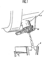
- FIG. 1 shows an overall view of the casting device.
- the metallurgical container is designated by the general reference 1.
- This container can be a dispatcher, or a pocket, or as in the example shown, a converter for the development of steel.
- a slide shutter, designated by the general reference 10 is fixed under the container. The steel contained in the converter is poured into a pocket 3.
- FIG. 2 shows a schematic view in section of the device.
- the steel wall 2 of the container is covered by a protective layer 4 of refractory material, for example bricks.
- a taphole 6 allows the exit of the metal out of the converter.
- the hole of this hole is delimited by a surface outer 8, flat in the example shown. This surface 8 constitutes a joining surface.
- the slide shutter 10 fixed under the container consists of a frame 12 fixed on the outer wall 2 of the metallurgical container.
- a set two plates namely a fixed plate 14 and a movable plate 16.
- Each of the plates comprises one or more holes for the passage of the metal and is surrounded by a frame, respectively 20 and 22. These two plates are enclosed in a housing 24.
- pressure means schematically represented by the springs 26 allow to press the fixed plate 14 against the movable plate 16.
- An actuating means such as a hydraulic cylinder 28, whose rod is connected to the frame 22 of the movable plate can move the movable plate relative to the fixed plate. This displacement allows, in known manner, to vary the recovery holes of the two plates so to control or stop completely the passage of the metal.
- the drawer includes only two plates, it could include more, for example three or more.
- the housing 24 is in turn pressed by pressing means 30 against the surface 8, which ends the pouring orifice so that the back of the plate fixed, which has a fitting surface 32 adapted at surface 8 be applied sufficiently strongly to create a metal seal.
- Surface qualities in the presence of course are of sufficient quality to ensure this tightness.
- the joining surface must be large enough so that means pressure do not exert effort cantilever. Since the pressure means to tighten against each other the fixed plate and the movable plate are different pressure means for pressing the surface of joining the fixed plate against the surface of junction of the pouring orifice, it is possible to vary pressures per unit area independently one from the other.
- the guiding surface 34 may be slightly behind this plan, as shown in fig 2.
- a chamfer will be then provided on the fixed plate or on the joining surface to facilitate the installation of the fixed plate in absorbing the difference in level.
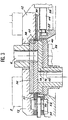
- FIGS. 3 and 4 show another mode embodiment of a casting device according to the invention.
- This device comprises a solid frame 12 fixed on an outer wall 2 of the metallurgical container.
- a plate of junction 36 reported and cemented on the end of the hole casting.
- the outer surface of this plate 36 constitutes the junction surface 8.
- the fixed plate is here consisting of the refractory plate itself and a envelope 38.
- the movable plate consists of the plate refractory itself, a support 40 and a nozzle collector 42, separate or made in one piece with the refractory plate.
- the means of pressure 26 will be described in more detail with reference to FIG. Note, however, that in this embodiment the clamping means of the fixed plate against the surface junction of the pouring orifice are the same as the pressure means for pressing the fixed plate 14 against the movable plate 16. The same means fill therefore two distinct functions.
- the fixed plate is placed in the training frame of the fixed plate 20 and the movable plate in the drive frame of the movable plate 22.
- the rod 44 of the cylinder 28 is retained in a frame housing driving the movable plate 22.
- the cylinder 28 allows to move the movable plate on the fixed plate of in a manner known to control the flow metal out of the metallurgical container.
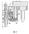
- FIG. 4 shows a sectional view of the embodiment shown in FIG. perpendicular cutting plane.
- This figure shows in particular the details of the designated means of pressure as a whole by the general reference 26. They comprise a helical spring 46 having one end is resting on the frame 12 and the other on a rocker arm 48. The rocker transmits the action of the spring, in the sense reverse, on the moving plate. Action on the mobile plate is retransmitted to the fixed plate, then to the junction plate 36.
- a latch 50 with two positions.
- This lock is rotatably mounted on the training frame 20 of the fixed plate. In a first position, shown in fig 3, he enters a dwelling 51 of the frame 12. In its other position it penetrates in a housing 53 provided in the training frame of the movable plate 22. In the first position it immobilizes the drive frame of the fixed plate relative to the frame and, in its second position, relative to to the drive frame of the movable plate.
- the cylinder 28 has a stroke sufficient to move all of the two frames enough to release the fixed plate of the right of way of the pressure the fixed plate against the junction surface of the orifice casting.
- the same medium namely the cylinder 28, performs successively two distinct functions.
- it allows to move the moving plate (first position of the latch 50).
- it serves to extracting the part to be changed and setting up a new fixed plate.
- the lock is placed in his second position. The action of the jack allows then move the fixed plate and the plate in a single block mobile, secured together by the lock 50.
- a fixed stop 52 is provided on the frame 12.
- the fixed plate 14 bears against this stop 52 at the end of its introduction.
- the latch 50 has a surface 54 constituting means of catching up play to lock the fixed plate against the stop 52 via the drive frame of the fixed plate.
- This surface 54 is for example a surface constituting a helical cam. So the fixed plate and the frame drive the fixed plate are together immobilized without play compared to the frame. This provision is intended to prevent relative movement of the plate fixed relative to the joining surface. Indeed the movable plate transmits sharp forces to the plate fixed. Such efforts, which are important, tend to move the fixed plate. If it was not blocked, she would move relative to the surface of junction of the pouring orifice, which would have the consequence detrimental wear of the surfaces in contact of the fixed plate and the joining surface.
- FIG. 5 shows a variant of realization of the drawer of Fig 3 in the open position.
- the parts of the same kind are designated by numbers identical reference numbers.
- the lock 50 is placed in said second position in which it secures the training frame 20 of the fixed plate 14 with the drive frame 22 of the movable plate 16.
- the jack 28, whose rod 44 is connected to the frame 22 of the mobile plate, was used to push the set constituted by the two training frames (fixed and mobile) and the plates housed in the openings of these frames (fixed plate 14 and plate mobile 16). This movement has been pursued sufficiently so that the fixed and mobile plates are entirely freed from the action of pressure this way they can be removed freely without have to open a door like this is usually done in the devices of the prior art.
- the installation of new plates is carried out in the same way.
- the fixed plate 14 is first placed inside the opening of the training frame 20 of the fixed plate on a bearing surface of frame 12 located (with close machining tolerances), in the extension of the joining surface.
- the moving plate is then placed on the fixed plate, inside the opening of the drive frame 22 of the movable plate. It is not necessary to connect or disconnect because the cylinder rod remains fixed, during these operations, on the drive frame of the plate mobile.
- the cylinder is then actuated to pull the assembly which penetrates laterally with respect to the pouring orifice under the locking means 50, which immobilizes the two plates without further operation.
- the fixed plate 14 is brought and / or withdrawn and slid under pressure means 30 prior to this that the fixed plate 14 does not begin to cover the orifice casting of the container.
- FIGS. 6 and 7 show two variants embodiment of the junction plate.
- the junction plate of the pouring orifice is constituted a refractory plate 56 surrounding the pouring orifice.
- the plate 56 is secured to a metal support 58 to ensure a rigid fixation on the container metallurgy, for example by means of screws, bolts, studs or the like arranged in the holes 60.
- the surface of the metal support 58 is co-planar, at less in part, with the joining surface 8. This may be obtained by a correction of these two surfaces after assembly of the refractory plate on the support metallic.
- the surface of the metal support 58 allows to enlarge the support surface of the fixed plate on the surface junction and avoid a cantilevered plate fixed.
- Plots 62 are fixed rigidly on the support 58 metal and co-planar machined with refractory plate 56 so as to enlarge the bearing surface of the fixed plate 14 against the joining surface 8.
- the pads 62 are made of a material compatible with that of the refractory plate 56 from the point of view of machining.
- the pads 62 are made in the same refractory material than that of the plate 56. Thus it is possible to machine them simultaneously without difficulty.
Landscapes
- Engineering & Computer Science (AREA)
- Mechanical Engineering (AREA)
- Manufacturing & Machinery (AREA)
- Carbon Steel Or Casting Steel Manufacturing (AREA)
- Casting Support Devices, Ladles, And Melt Control Thereby (AREA)
- Sliding Valves (AREA)
- Furnace Charging Or Discharging (AREA)
- Lift Valve (AREA)
Abstract
Description
L'invention concerne un dispositif de coulée comprenant un conteneur métallurgique muni d'un orifice de coulée, notamment un convertisseur pour l'élaboration de l'acier; un obturateur à tiroir pour ledit orifice de coulée, cet obturateur comprenant: au moins une plaque réfractaire fixe comportant un orifice placé en regard de l'orifice de coulée; au moins une plaque réfractaire mobile comportant au moins un orifice; des moyens de déplacement pour déplacer la plaque mobile par rapport à la plaque fixe de manière à commander le recouvrement des orifices de la plaque fixe et de la plaque mobile; des moyens de pression qui permettent de serrer la plaque mobile contre la plaque fixe.The invention relates to a casting device comprising a metallurgical container provided with an orifice casting, especially a converter for the elaboration steel; a slide shutter for said orifice casting, said shutter comprising: at least one fixed refractory plate having an orifice placed opposite the pouring orifice; at least one refractory plate mobile having at least one orifice; of the moving means for moving the movable plate relative to the fixed plate so as to control the covering the holes of the fixed plate and the plate mobile; pressure means which make it possible to tighten the movable plate against the fixed plate.
On connaít déjà des dispositifs de coulée de ce type. Dans la plupart d'entre eux, la plaque fixe de l'obturateur à tiroir est cimentée à l'extrémité de l'orifice de coulée extérieure au conteneur. Pour cela l'extrémité de l'orifice de coulée est enduite de ciment, et la plaque fixe est pressée contre cet extrémité.We already know casting devices of this type. In most of them, the fixed plate of the slide shutter is cemented at the end of the orifice pouring outside the container. For this purpose the end of the pouring orifice is coated with cement, and the plate fixed is pressed against this end.
Cependant il est nécessaire de changer périodiquement les plaques réfractaires par suite de leur érosion, principalement à cause des mouvements du tiroir. Un tel changement nécessite d'abord de défaire le joint de ciment, puis de nettoyer la face extérieure de l'orifice de coulée du ciment qui a servi à fixer la plaque usagée. Ce nettoyage est généralement effectué à l'aide d'un burin et d'un marteau. Enfin il faut faire un nouveau joint de ciment pour fixer la plaque neuve.However it is necessary to change periodically refractory plates as a result of their erosion, mainly because of the movements of the drawer. Such a change requires first to undo the seal of cement, then clean the outer face of the orifice casting of the cement used to fix the used plate. This cleaning is usually done using a chisel and hammer. Finally you have to make a new seal of cement to fix the new plate.
Ce procédé connu occasionne de nombreux inconvénients. Le nettoyage de la face extérieure de l'orifice de coulée est effectuée dans des conditions très pénibles pour l'ouvrier.This known process causes many disadvantages. The cleaning of the outer face of the pouring orifice is made under very painful for the worker.
En effet on ne peut généralement pas attendre le refroidissement du conteneur métallurgique parce que la durée de ce refroidissement conduirait à une immobilisation coûteuse du conteneur.Indeed we can not usually wait the cooling of the metallurgical container because that the duration of this cooling would lead to immobilization expensive container.
De plus il y a des risques d'endommager l'orifice de coulée lorsqu'on le nettoie et de réduire en conséquence sa durée de fonctionnement.In addition there is a risk of damaging the orifice when it is cleaned and reduced accordingly its running time.
Enfin il est nécessaire que la plaque fixe soit mise en place du premier coup parce que le ciment prend rapidement en raison de la température élevée de l'orifice de coulée. Si la plaque a été mal posée, il sera nécessaire de refaire complètement le joint.Finally it is necessary that the fixed plate is put in place the first time because the cement takes quickly because of the high temperature of the pouring orifice. If the plate has been incorrectly placed, will be necessary to completely redo the joint.
Ces inconvénients sont particulièrement aggravés dans le cas des convertisseurs pour lesquels tout arrêt implique une perte de production. Même le temps nécessaire au nettoyage doit être réduit au minimum. Les conditions de travail sont donc particulièrement pénibles, d'autant plus que les dimensions de l'obturateur à tiroir sont beaucoup plus grandes que celles des autres conteneurs (poches, répartiteurs) et que le convertisseur, contrairement aux poches et aux répartiteurs, ne peut être déplacé hors de son ambiance de -travail.These disadvantages are particularly aggravated in the case of converters for which any stop implies a loss of production. Even the time required for cleaning must be kept to a minimum. Working conditions are therefore particularly painful, especially as the dimensions of the shutter drawer are much larger than those other containers (pouches, dispatchers) and that the converter, unlike pockets and splitters, can not be moved out of its ambience -job.
On connait également (FR-A-2 436 923) un
obturateur à tiroir muni d'une plaque d'obturation pleine
ou comportant un trou de passage pour le métal. Cette
plaque d'obturation est disposée entre deux plaques,
respectivement une plaque supérieure et une plaque de
support inférieure sur laquelle est fixé un tube de coulée.
Dans un dispositif de ce genre, la plaque supérieure est
une plaque de travail. En d'autres termes, la plaque
d'obturation frotte contre sa face inférieure à chaque
mouvement du tiroir. Cette face s'érode donc relativement
rapidement ce qui oblige à changer la plaque supérieure
à chaque changement de la plaque d'obturation.
On connaít également (JP-49-105730) un dispositif destiné à assembler
un jeu de plaques réfractaires sans un récipient de coulée. Ce dispositif
ne comporte pas de surfaces de fonction planes.Also known (FR-A-2 436 923) is a shutter with a shutter plate solid or having a through hole for the metal. This shutter plate is disposed between two plates, respectively an upper plate and a lower support plate on which is fixed a pouring tube. In such a device, the top plate is a work plate. In other words, the shutter plate rubs against its underside with each movement of the drawer. This face is thus eroded relatively quickly which requires changing the upper plate at each change of the sealing plate.
It is also known (JP-49-105730) a device for assembling a set of refractory plates without a casting vessel. This device does not have planar function surfaces.
On connaít également (DE 20 27 881), un dispositif pour le remplacement des réfractaires utilisés pour transférer de l'acier liquide d'un répartiteur vers un moule de coulée. Il comporte une plaque de jonction, montée à l'extrémité de l'orifice de coulée du répartiteur, et au moins deux ensembles constitués chacun par une plaque fixe et une plaque mobile solidaire d'un tube de coulée. Ces ensembles sont montés sur des rails de guidage, de sorte qu'un ensemble de réfractaires usé peut être remplacé par un ensemble neuf, l'un chassant l'autre.Also known (DE 20 27 881), a device for the replacement of refractories used to transfer liquid steel from a dispatcher to a casting mold. It has a junction plate, mounted at the end of the tundish orifice, and at least two sets each consisting of a fixed plate and a movable plate secured to a tube of casting. These assemblies are mounted on guide rails, so that a used refractory set can be replaced by a new set, one chasing the other.
Un tel dispositif est prévu pour le remplacement des réfractaires durant la coulée, et non entre deux coulées. Il ne peut donc permettre un accès à la plaque de jonction en vue de la vérifier et éventuellement de la changer.Such a device is provided for replacement refractories during casting, and not between two flows. It can not therefore allow access to the plate junction in order to check it and possibly to change.
En outre, un ensemble de réfractaires neufs est introduit d'un côté de l'orifice de coulée, tandis que l'ensemble de réfractaires usagés est évacué du côté opposé. Dans le cas où les réfractaires sont changés plusieurs fois de suite, l'introduction des réfractaires neufs doit se faire alternativement d'un côté puis de l'autre de l'orifice de coulée.Le dispositif nécessite donc trois zones distinctes, à savoir une zone d'introduction des réfractaires neufs, une zone de coulée, et une zone d'évacuation des réfractaires usagés. Son encombrement est donc au moins égal à trois longueurs de plaques.In addition, a set of new refractories is introduced on one side of the pouring orifice, while the used refractory assembly is evacuated from the opposite. In case the refractories are changed several times in a row, the introduction of refractories must be done alternately on one side then the other of the pouring orifice.The device thus requires three distinct zones, namely an introductory zone new refractories, a casting zone, and a zone evacuation of used refractories. Its size is therefore at least equal to three lengths of plates.
Enfin, le dispositif ne décrit aucun moyen permettant de mettre les réfractaires en place et de les retirer aisément.Finally, the device does not describe any means to put the refractories in place and remove them easily.
La présente invention a pour objet un dispositif
de coulée et un procédé de mise en oeuvre de ce dispositif
qui résolvent ces problèmes.
La présente invention a également pour objet l'utilisation d'une plaque selon la revendication 16.The present invention relates to a device
casting and a method of implementing this device
who solve these problems.
The present invention also relates to the use of a plate according to
Ces buts sont atteints grâce aux caractéristiques de la revendication 1. Grâce à ces caractéristiques, l'introduction et l'extraction des plaques se font du même coté du tiroir. Par suite, l'encombrement est limité à la longueur de deux plaques, ce qui est un avantage lorsque la place disponible est réduite, comme c'est généralement le cas, particulièrement en ce qui concerne les appitcations aux poches et aux convertisseurs.These goals are achieved through the characteristics of claim 1. With these features, the introduction and the extraction of the plates are same side of the drawer. As a result, the clutter is limited to the length of two plates, which is a benefit when the available space is reduced, as is usually the case the case, particularly as regards the pockets and converters appitcations.
De préférence, le dispositif comporte une surface de guidage prolongeant sensiblement la surface de jonction de l'orifice de coulée dans la zone d'introduction/extraction, de manière à assurer un pré-guidage de la plaque fixe par rapport à la surface de jonction de l'orifice de coulée afin de faciliter la mise en place et/ou le retrait d'au moins la plaque fixe par glissement sur la surface de jonction.Preferably, the device comprises a surface substantially extending the surface of the connection of the pouring orifice in the introduction / extraction zone, in order to ensure pre-guidance of the fixed plate relative to the junction surface of the pouring orifice to facilitate placement and / or removing at least the fixed plate by sliding on the joining surface.
Ainsi des plaques fixes et mobiles usagées peuvent en être retirées aisément de l'obturateur après la coulée. Il suffit en effet de les faire glisser jusque à ce qu'elles échappent aux moyens de pression. Dans cette position, elles sont libres et peuvent être retirées aisément, soit l'une après l'autre, soit simultanément, sans avoir à ouvrir une porte comme cela se fait généralement dans les dispositifs de l'art antérieur. Les plaques ayant été extraites, l'accès à la surface de jonction est dégagé et on peut examiner et nettoyer cette dernière.Thus used fixed and mobile plates can be easily removed from the shutter after the casting. Just drag them that they escape the means of pressure. In this position, they are free and can be removed easily, either one after the other, or simultaneously, without have to open a door like this is usually done in the devices of the prior art. The plaques having been extracted, access to the junction area is cleared and can be examined and cleaned.
Pour la mise en place de plaques neuves dans le tiroir, on effectue les mêmes opérations en sens inverse. On monte d'abord la plaque fixe sur la surface de guidage, puis la plaque mobile sur la plaque fixe (en variante, on peut mettre les deux plaques sur la surface de guidage en une opération unique) et on les pousse latéralement sous les moyens de pression.For the placement of new plates in the drawer, the same operations are performed in the opposite direction. We first mount the fixed plate on the surface of guide, then the movable plate on the fixed plate (alternatively, we can put the two plates on the surface guidance in a single operation) and pushes them laterally under the pressure means.
La surface de jonction de l'orifice de coulée et la surface de jonction de la plaque fixe sont planes. La planéité de ces deux surfaces facilite aussi la mis en place et/ou le retrait de la plaque fixe par glissement sur la surface de jonction de l'orifice de coulée.The junction surface of the orifice casting and the joining surface of the fixed plate are planar. The flatness of these two surfaces also makes it easier to in place and / or removal of the fixed plate by sliding on the joining surface of the pouring orifice.
Dans une réalisation préférée la surface de jonction de l'orifice de coulée est constituée d'une plaque réfractaire. Cette plaque est changée entre deux coulées alors que le conteneur est vide et que l'acier ne coule pas. Il est donc impossible que de l'acier s'introduise entre cette plaque de jonction et la plaque fixe.In a preferred embodiment the surface of junction of the pouring orifice consists of a plate refractory. This plate is changed between two when the container is empty and the steel is not do not run. It is therefore impossible for steel to penetrate between this junction plate and the fixed plate.
Il en va autrement dans le cas de la plaque supérieure du document FR-A-2 436 923. L'acierpeut s'introduire entre la plaque supérieure fixe et la plaque d'obturation parce que cette dernière est manoeuvrée en présence de l'acier.The situation is different in the case of the upper plate of document FR-A-2 436 923. Steel can be introduced between the fixed upper plate and the blanking plate because the latter is maneuvered into presence of steel.
L'idéal serait que la surface de guidage soit exactement au même niveau que la surface de jonction. Mais cela n'est pas réalisable mécaniquement à cause des tolérances d'usinage. Le niveau de la surface de guidage est donc égal par défaut (c'est-à-dire aux tolérances d'usinage près) au niveau de la surface de jonction de l'orifice de coulée, un chanfrein étant prévu pour faciliter la mise en place de la plaque fixe sur la surface de jonction de l'orifice de coulée.Ideally, the guide surface should be exactly the same level as the joining surface. But this is not mechanically feasible because machining tolerances. The level of the surface of guidance is therefore equal by default (ie to the tolerances machining near) at the joining surface of the pouring orifice, a chamfer being provided for facilitate the placement of the fixed plate on the surface junction of the pouring orifice.
De préférence les moyens de pression pour serrer la surface de jonction de la plaque fixe contre la surface de jonction de l'orifice de coulée sont agencés de manière à agir pendant la mise en place et/ou le retrait par glissement d'au moins la plaque fixe afin d'éliminer les déchets restés éventuellement sur cette surface.Preferably the pressure means for tighten the joining surface of the fixed plate against the junction surface of the pouring orifice are arranged to act during set-up and / or removal by sliding at least the fixed plate to eliminate the waste possibly remaining on this surface.
Les moyens de déplacement pour mettre en place et/ou retirer la plaque fixe par glissement sur la surface de jonction de l'orifice de coulée sont de préférence les mêmes que les moyens pour déplacer la plaque mobile par rapport à la plaque fixe.Means of travel to implement place and / or remove the fixed plate by sliding on the junction surface of the pouring orifice are preferably the same as the means to move the plate mobile relative to the fixed plate.
Le dispositif comporte de préférence: un bâti; un cadre d'entraínement de la plaque fixe; un cadre d'entraínement de la plaque mobile; des moyens de déplacement du cadre d'entraínement de la plaque mobile, ces moyens constituant les moyens de déplacement de la plaque mobile mentionnés précédemment; des moyens pour solidariser le cadre d'entraínement de la plaque fixe soit avec le bâti, soit avec le cadre d'entraínement de la plaque mobile.The device preferably comprises: a frame; a frame for driving the fixed plate; a frame driving the movable plate; moving means the drive frame of the movable plate, these means constituting the means of displacement of the movable plate mentioned above; of the means of securing the training framework of the fixed plate either with the frame or with the training frame of the movable plate.
Les moyens pour solidariser le cadre d'entraínement
de la plaque fixe soit avec le bâti, soit avec le
cadre d'entraínement de la plaque mobile sont, dans un
mode préféré, constitués par un verrou à deux positions
monté sur le cadre d'entraínement de la plaque fixe, ce
verrou immobilisant le cadre d'entraínement de la plaque
fixe par rapport au bâti dans une première position
et par rapport au cadre d'entraínement de laplaque mobile
dans la seconde position, les moyens de déplacement
du cadre d'entraínement de la plaque mobile présentant
une course suffisante pour déplacer l'ensemble
des deux cadres jusqu'à libérer la plaque fixe de l'emprise
des moyens de pression de la plaque fixe contre
la surface de jonction de l'orifice de coulée.
De préférence le dispositif comporte une butée fixe par
rapport au bâti contre laquelle la plaque fixe vient en
butée en fin d'introduction, le verrou comportant des
moyens de récupération de jeu pour bloquer ladite plaque
fixe contre la butée par l'intermédiaire du cadre
d'entraínement de la plaque fixe de telle sorte que la
plaque fixe et le cadre d'entraínement de la plaque fixe
sont ensemble immobilisés par rapport au bâti.The means for securing the drive frame of the fixed plate with the frame or with the drive frame of the movable plate are, in a preferred embodiment, constituted by a two-position latch mounted on the drive frame. of the fixed plate, this lock immobilizing the drive frame of the fixed plate relative to the frame in a first position and relative to the drive frame of the mobile platform in the second position, the moving means of the drive frame the movable plate having a sufficient stroke to move all of the two frames to release the fixed plate of the grip of the pressure means of the fixed plate against the junction surface of the casting orifice.
Preferably the device comprises a fixed stop relative to the frame against which the fixed plate comes into abutment at the end of introduction, the lock comprising means for recovering clearance to lock said fixed plate against the stop via the frame of drive of the fixed plate so that the fixed plate and the drive frame of the fixed plate are together immobilized relative to the frame.
Les moyens de serrage de la plaque fixe contre la surface de jonction de l'orifice de coulée sont de préférence les mêmes que les moyens de pression pour presser la plaque mobile contre la plaque fixe.The clamping means of the fixed plate against the junction area of the pouring orifice are preferably the same as the pressure means for press the movable plate against the fixed plate.
La surface de jonction de l'orifice de coulée peut être constituée d'une plaque réfractaire entourant l'orifice de coulée montée sur un support métallique permettant d'assurer une fixation rigide de ladite plaque réfractaire sur le conteneur métallurgique.The joining surface of the pouring orifice may consist of a refractory plate surrounding the pouring orifice mounted on a metal support allowing to ensure a rigid fixation of said refractory plate on the metallurgical container.
Le support métallique peut présenter au moins une portion de surface co-planaire avec la plaque réfractaire de manière à agrandir la surface d'appui de la plaque fixe sur la surface de jonction de l'orifice de coulée.The metal support may have at least a portion of co-planar surface with the refractory plate in order to enlarge the support surface of the fixed plate on the junction surface of the pouring orifice.
Des plots en une matière compatible avec celle de la plaque réfractaire du point de vue d'un usinage au moyen d'un même outil peuvent être fixés rigidement sur le support métallique et usinés co-planaires avec la plaque réfractaire de manière à agrandir la surface d'appui de la plaque fixe contre la surface de jonction.Plots made of a material compatible with that of the refractory plate from the point of view of machining by the same tool can be rigidly attached on the metal support and machined co-planar with the refractory plate so as to enlarge the support surface of the fixed plate against the joining surface.
L'invention concerne également un procédé de mise en oeuvre du dispositif. Ce procédé de remplacement d'au moins la plaquefixe dudit obturateur à tiroir se caractérise en ce que:
- on retire une plaque fixe et une plaque mobile usagées des moyens de pression en les faisant glisser latéralement par rapport à l'orifice de coulée vers une zone d'introduction/extraction;
- on évacue la plaque fixe et la plaque mobile hors du tiroir;
- on place une plaque fixe et un plaque mobile neuves l'une après l'autre ou simultanément dans la zone d'introduction/extraction;
- on fait glisser latéralement la plaque fixe et la plaque mobile sous les moyens de pression.
- removing a used fixed plate and a movable plate from the pressure means by sliding them laterally with respect to the pouring orifice towards an introduction / extraction zone;
- the fixed plate and the movable plate are removed from the drawer;
- a new fixed plate and a movable plate are placed one after the other or simultaneously in the introduction / extraction zone;
- the fixed plate and the movable plate are slid laterally under the pressure means.
De préférence au moins la plaque fixe est amenée et/ou retirée latéralement par rapport à l'orifice de coulée et glissée sous des moyens de pression préalablement à ce que la plaque fixe ne commence à recouvrir et/ou découvrir l'orifice de coulée du conteneur.Preferably at least the fixed plate is brought and / or withdrawn laterally with respect to the cast and slid under pressure prior the fixed plate does not begin to cover and / or discover the pouring orifice of the container.
D'autres caractéristiques et avantages de la présente invention apparaítront encore à la lecture de la description qui suit d'exemples de réalisations donnés, à titre purement illustratif, en référence aux figures annexées. Sur ces figures:
- la fig 1 est une vue d'ensemble qui montre un dispositif de coulée conforme à l'invention;
- la fig 2 est une vue schématique en coupe qui illustre le dispositif et le procédé de l'invention;
- la fig 3 est une vue en coupe d'un mode de réalisation préféré de la présente invention;
- la fig 4 est une vue en coupe du mode de réalisation représenté sur la fig 3, selon un plan de coupe perpendiculaire, qui montre en particulier les moyens de pression de ce dispositif;
- la fig 5 est une vue en coupe d'une variante du mode de réalisation des figures 3 et 4 représenté en position ouverte;
- la fig 6 est une vue en coupe d'un mode de réalisation particulier de la surface de jonction de l'orifice de coulée;
- la fig 7 est une vue en coupe d'un autre mode de réalisation particulier de la surface de jonction de l'orifice de coulée.
- Fig 1 is an overview which shows a casting device according to the invention;
- Figure 2 is a schematic sectional view illustrating the device and method of the invention;
- Fig. 3 is a sectional view of a preferred embodiment of the present invention;
- FIG 4 is a sectional view of the embodiment shown in Figure 3, in a perpendicular sectional plane, which shows in particular the pressure means of this device;
- Figure 5 is a sectional view of a variant of the embodiment of Figures 3 and 4 shown in the open position;
- Fig 6 is a sectional view of a particular embodiment of the junction surface of the pouring orifice;
- Figure 7 is a sectional view of another particular embodiment of the junction surface of the pouring orifice.
On a représenté sur la figure 1 une vue d'ensemble
du dispositif de coulée. Le conteneur métallurgique
est désigné par la référence générale 1. Ce conteneur
peut être un répartiteur, ou une poche, ou encore,
comme dans l'exemple illustré, un convertisseur pour
l'élaboration de l'acier. Un obturateur à tiroir, désigné par
la référence générale 10, est fixé sous le conteneur.
L'acier contenu dans le convertisseur est versé dans
une poche 3.FIG. 1 shows an overall view
of the casting device. The metallurgical container
is designated by the general reference 1. This container
can be a dispatcher, or a pocket, or
as in the example shown, a converter for
the development of steel. A slide shutter, designated by
the
On a représenté sur la figure 2 une vue schématique
en coupe du dispositif. La paroi d'acier 2 du
conteneur est recouverte par une couche protectrice 4
de matériau réfractaire, par exemple des briques. Un
trou de coulée 6 permet la sortie du métal hors du convertisseur.
L'orifice de ce trou est délimité par une surface
extérieure 8, plane dans l'exemple représenté. Cette
surface 8 constitue une surface de jonction.FIG. 2 shows a schematic view
in section of the device. The
L'obturateur à tiroir 10 fixé sous le conteneur
se compose d'un bâti 12 fixé sur la paroi extérieure 2 du
conteneur métallurgique. Dans le bâti on trouve un ensemble
de deux plaques, à savoir une plaque fixe 14 et
une plaque mobile 16. Chacune des plaques comporte
un ou plusieurs orifices pour le passage du métal et est
entourée par un cadre, respectivement 20 et 22. Ces
deux plaques sont enfermées dans un boítier 24. Des
moyens de pression, représentés schématiquement par
les ressorts 26, permettent de presser la plaque fixe 14
contre la plaque mobile 16. Un moyen d'actionnement,
tel qu'un vérin hydraulique 28, dont la tige est connectée
au cadre 22 de la plaque mobile permet de déplacer la
plaque mobile par rapport à la plaque fixe. Ce déplacement
permet, de manière connue, de faire varier le recouvrement
des orifices des deux plaques de manière
à contrôler ou arrêter totalement le passage du métal.
Bien que, dans l'exemple représenté, le tiroir comporte
deux plaques seulement, il pourrait en comporter davantage,
par exemple trois ou plus.The
Le boítier 24 est à son tour pressé par des
moyens de pression 30 contre la surface 8, qui termine
l'orifice de coulée de manière que le dos de la plaque
fixe, qui comporte une surface de jonction 32 adaptée
à la surface 8 soit appliqué de façon suffisamment forte
pour créer une étanchéité au métal. Les qualités de surfaces
en présence sont bien entendu de qualité suffisante
pour assurer cette étanchéité. La surface de jonction
doit être suffisamment grande pour que les moyens
de pression n'exercent pas d'effort en porte-à-faux.
Etant donné que les moyens de pression pour serrer
l'une contre l'autre la plaque fixe et la plaque mobile sont
différents des moyens de pression pour plaquer la surface
de jonction de la plaque fixe contre la surface de
jonction de l'orifice de coulée, il est possible de faire varier
les pressions par unité de surface indépendamment
l'une de l'autre.The
Etant donné qu'il n'y a pas de mouvement relatif
de la plaque fixe par rapport à la surface de jonction,
et que, d'autre part, les moyens de pressions sont concentrés
autour de l'orifice de coulée, il n'est pas nécessaire
de disposer d'une surface d'appui de la plaque fixe
sur la surface de jonction au delà de la zone soumise à
l'action des moyens de pression. Par suite la surface de
jonction 8 est plus petite que la plaque fixe. C'est pourquoi
il est avantageux de prévoir des moyens pour faciliter
la mise en place et/ou le retrait d'au moins la plaque
fixe par glissement sur ladite surface plane de jonction.
Ces moyens sont constitués par une surface de
guidage 34. Cette surface est située du côté de l'orifice
de coulée 6 par où la plaque fixe doit être introduite. Elle
est située sensiblement dans le plan de la surface de
jonction. Toutefois, comme il n'est pas possible, compte
tenu des tolérances de fabrication, de réaliser deux surface
parfaitement co-planaires, la surface de guidage
34 pourra être légèrement en retrait par rapport à ce
plan, comme représenté sur la fig 2. Un chanfrein sera
alors prévu sur la plaque fixe ou sur la surface de jonction
pour faciliter la mise en place de la plaque fixe en
absorbant la différence de niveau.Since there is no relative movement
of the fixed plate relative to the joining surface,
and that, on the other hand, the pressure means are concentrated
around the pouring orifice, it is not necessary
to have a support surface of the fixed plate
on the junction area beyond the area subject to
the action of the pressure means. As a result the surface of
Dans l'exemple représenté on change non seulement la plaque fixe seule, mais l'ensemble du boítier comprenant les deux plaques. Ce changement s'effectue de la manière suivante.In the example shown we change no only the fixed plate alone, but the entire housing comprising the two plates. This change is made as follows.
On retire d'abord le boítier 24 contenant les
plaques fixe(s) et mobile(s) usagées en les faisant glisser
sur la surface de jonction 8 puis sur la surface de
guidage 34 à l'aide du vérin 28 jusqu'à ce qu'ils ne soient
plus soumis à l'action des moyens de pression 30. Ceci
a pour effet de cisailler les déchets qui se trouvent sur
la surface de jonction. En particulier, si un anneau
d'acier s'est formé à la jonction entre la surface de jonction
de l'orifice de coulée et la plaque fixe, cet anneau
sera cisaillé et les déchets évacués par le trou de coulée
6. Le boítier est ensuite déconnecté de la tige du vérin
28 et déposé.First remove the
On met un nouveau boítier 24 contenant des
plaques neuves sur la surface d'appui 34, on connecte
la tige du vérin, puis on introduit le boítier en le faisant
glisser sur la surface de guidage 34. Il est introduit sous
les moyens de pression 30 avant que la surface de jonction
de la plaque fixe ne monte sur la surface de jonction
8. Lorsque cela se produit, les moyens de pression agissent
de sorte que la surface de jonction est nettoyée.We put a
On a représenté sur les fig 3 et 4 un autre mode
de réalisation d'un dispositif de coulée conforme à l'invention.
Ce dispositif comporte un bâti massif 12 fixé
sur une paroi extérieure 2 du conteneur métallurgique.
Dans un évidement du bâti est montée une plaque de
jonction 36 rapportée et cimentée sur l'extrémité du trou
de coulée. La surface extérieure de cette plaque 36
constitue la surface de jonction 8. La plaque fixe est ici
constituée de la plaque réfractaire elle-même et d'une
enveloppe 38. La plaque mobile est constituée de la plaque
réfractaire elle-même, d'un support 40 et d'une busette
collectrice 42, séparée ou réalisée d'une seule pièce
avec la plaque réfractaire. Les moyens de pression
26 seront décrits plus en détail en référence à la fig 4.
On note cependant que dans ce mode de réalisation les
moyens de serrage de la plaque fixe contre la surface
de jonction de l'orifice de coulée sont les mêmes que
les moyens de pression pour presser la plaque fixe 14
contre la plaque mobile 16. Les mêmes moyens remplissent
donc deux fonctions distinctes.FIGS. 3 and 4 show another mode
embodiment of a casting device according to the invention.
This device comprises a
La plaque fixe est placée dans le cadre d'entraínement
de la plaque fixe 20 et la plaque mobile dans
le cadre d'entraínement de la plaque mobile 22. La tige
44 du vérin 28 est retenue dans un logement du cadre
d'entraínement de la plaque mobile 22. Le vérin 28 permet
de déplacer la plaque mobile sur la plaque fixe de
manière à contrôler, de manière connue, l'écoulement
du métal hors du conteneur métallurgique.The fixed plate is placed in the training frame
of the fixed
On a représenté sur la fig 4 une vue en coupe
du mode de réalisation représenté sur la fig 3, selon un
plan de coupe perpendiculaire. Cette figure montre en
particulier le détail des moyens de pression désignés
dans leur ensemble par la référence générale 26. Ils
comprennent un ressort hélicoïdal 46 dont une extrémité
est en appui sur le bâti 12 et l'autre sur un culbuteur
48. Le culbuteur transmet l'action du ressort, en sens
inverse, sur la plaque mobile. L'action exercée sur la
plaque mobile est retransmise à la plaque fixe, puis à la
plaque de jonction 36.FIG. 4 shows a sectional view
of the embodiment shown in FIG.
perpendicular cutting plane. This figure shows in
particular the details of the designated means of pressure
as a whole by the
Revenant à la fig 3, on décrira maintenant en
détail les moyens pour solidariser le cadre 20 d'entraínement
de la plaque fixe soit avec le bâti 12, soit avec
le cadre 22 d'entraínement de la plaque mobile. Ces
moyens sont constitués par un verrou 50 à deux positions.
Ce verrou est monté tournant sur le cadre 20 d'entraínement
de la plaque fixe. Dans une première position,
représentée sur la fig 3, il pénètre dans un logement
51 du bâti 12. Dans son autre position il pénètre
dans un logement 53 prévu dans le cadre d'entraínement
de la plaque mobile 22. Dans la première position
il immobilise le cadre d'entraínement de la plaque fixe
par rapport au bâti et, dans sa seconde position, par rapport
au cadre d'entraínement de la plaque mobile. Le
vérin 28 présente une course suffisante pour déplacer
l'ensemble des deux cadres suffisamment pour libérer
la plaque fixe de l'emprise des moyens de pression de
la plaque fixe contre la surface de jonction de l'orifice
de coulée.Returning to Fig 3, we will now describe in
detail means to secure the
Grâce au verrou à deux positions 50, le même
moyen, à savoir le vérin 28, réalise successivement
deux fonctions distinctes. D'une part, de manière conventionnelle,
il permet de déplacer la plaque mobile
(première position du verrou 50). D'autre part, il sert à
l'extraction de la partie à changer et à la mise en place
d'une nouvelle plaque fixe. Pour cela le verrou est placé
dans sa deuxième position. L'action du vérin permet
alors de déplacer d'un seul bloc la plaque fixe et la plaque
mobile, solidarisées entre elles par le verrou 50.Thanks to the two-
Une butée fixe 52 est prévue sur le bâti 12. La
plaque fixe 14 vient en appui contre cette butée 52 à la
fin de son introduction. Le verrou 50 comporte une surface
54 constituant des moyens de rattrapage de jeu
pour bloquer la plaque fixe contre la butée 52 par l'intermédiaire
du cadre d'entraínement de la plaque fixe.
Cette surface 54 est par exemple une surface constituant
une came hélicoïdale. Ainsi la plaque fixe et le cadre
d'entraínement de la plaque fixe sont ensemble immobilisés
sans jeu par rapport au bâti. Cette disposition
a pour but d'empêcher un mouvement relatif de la plaque
fixe par rapport à la surface de jonction. En effet la
plaque mobile transmet des efforts tranchants à la plaque
fixe. De tels efforts, qui sont importants, tendent à
déplacer la plaque fixe. Si cette dernière n'était pas bloquée,
elle se déplacerait par rapport à la surface de
jonction de l'orifice de coulée, ce qui aurait pour conséquence
une usure préjudiciable des surfaces en contact
de la plaque fixe et de la surface de jonction.A fixed
On a représenté sur la fig 5, une variante de
réalisation du tiroir de la fig 3 en position ouverte. Les
pièces de même nature sont désignées par des numéros
de référence identiques. On remarque que le verrou
50 est placé dans ladite deuxième position dans laquelle
il solidarise la cadre d'entraínement 20 de la plaque fixe
14 avec le cadre d'entraínement 22 de la plaque mobile
16. Le vérin 28, dont la tige 44 est connectée au cadre
22 d'entraínement de la plaque mobile, a été utilisé pour
pousser l'ensemble constitué par les deux cadres d'entraínement
(fixe et mobile) et les plaques logées dans
les ouvertures de ces cadres (plaque fixe 14 et plaque
mobile 16). Ce mouvement a été poursuivi suffisamment
pour que les plaques fixe et mobile soient entièrement
libérées de l'action de moyens de pression 26. De
cette manière elles peuvent être retirées librement sans
avoir à ouvrir une porte comme cela se fait généralement
dans les dispositifs de l'art antérieur.FIG. 5 shows a variant of
realization of the drawer of Fig 3 in the open position. The
parts of the same kind are designated by numbers
identical reference numbers. We notice that the
La mise en place de nouvelles plaques s'effectue
de la même manière. La plaque fixe 14 est d'abord
posée à l'intérieur de l'ouverture du cadre d'entraínement
20 de la plaque fixe sur une surface d'appui du
bâti 12 située (aux tolérances d'usinage près), dans le
prolongement de la surface de jonction. La plaque mobile
est ensuite posée sur la plaque fixe, à l'intérieur de
l'ouverture du cadre d'entraínement 22 de la plaque mobile.
Il n'est nécessaire d'effectuer ni connexion ni déconnexion
parce que la tige du vérin reste fixée, pendant
ces opérations, sur le cadre d'entraínement de la plaque
mobile. Le vérin est alors actionné pour tirer l'ensemble
qui pénètre latéralement par rapport à l'orifice de coulée
sous les moyens de verrouillage 50, ce qui immobilise
les deux plaques sans autre opération supplémentaire.
La plaque fixe 14 est amenée et/ou retirée et glissée
sous des moyens de pression 30 préalablement à ce
que la plaque fixe 14 ne commence à recouvrir l'orifice
de coulée du conteneur.The installation of new plates is carried out
in the same way. The fixed
On a représenté sur les fig 6 et 7 deux variantes
de réalisation de la plaque de jonction. Sur la fig 6,
la plaque de jonction de l'orifice de coulée est constituée
d'une plaque réfractaire 56 entourant l'orifice de coulée.
La plaque 56 est solidaire d'un support métallique 58
permettant d'assurer une fixation rigide sur le conteneur
métallurgique, par exemple par le biais de vis, de boulons,
goujons ou analogue disposés dans les trous 60.
La surface du support métallique 58 est co-planaire, au
moins en partie, avec la surface de jonction 8. Ceci peut
être obtenu par une rectification de ces deux surfaces
après assemblage de la plaque réfractaire sur le support
métallique. La surface du support métallique 58 permet
d'agrandir la surface d'appui de la plaque fixe sur la surface
de jonction et d'éviter un porte-à-faux de la plaque
fixe.FIGS. 6 and 7 show two variants
embodiment of the junction plate. In fig 6,
the junction plate of the pouring orifice is constituted
a
Il n'est pas aisé d'usiner un métal tel que l'acier
en même temps qu'un matériau réfractaire. En effet les
meules qui conviennent pour l'acier ne sont pas adaptées
aux matériaux réfractaires et inversement. Le mode
de réalisation de la fig 7 permet de surmonter ce problème.
Des plots 62 sont fixés rigidement sur le support
métallique 58 et usinés co-planaires avec la plaque réfractaire
56 de manière à agrandir la surface d'appui de
la plaque fixe 14 contre la surface de jonction 8. Les
plots 62 sont réalisés en une matière compatible avec
celle de la plaque réfractaire 56 du point de vue de l'usinage.
Par exemple les plots 62 sont réalisés dans le même
matériau réfractaire que celui de la plaque 56. Ainsi
il est possible de les usiner simultanément sans difficultés.It is not easy to machine a metal such as steel
at the same time as a refractory material. Indeed,
wheels that are suitable for steel are not suitable
to refractory materials and vice versa. The mode
embodiment of FIG 7 overcomes this problem.
Claims (18)
- Casting device comprising:a metallurgical vessel having a discharge opening (6), in particular a converter for the steel process;a slide gate for said discharge opening, said slide gate comprising:at least one fixed refractory plate (14) having an opening arranged in register with the discharge opening;at least one movable refractory plate (16) having at least one opening;displacing means for displacing (28) the movable plate (16) with respect to the fixed plate (14) in order to control the overlap of the openings of the fixed plate (14) and the movable plate (16);compression means (26) for tightening the movable plate (16) against the fixed plate (14);the discharge opening (6) of metallurgical vessel being designed to include a joint surface (8) to the fixed plate (14) of the slide gate;the fixed plate (14) comprising a joint surface (32) matching the joint surface (8) of the discharge opening of metallurgical vessel;the joint surface (8) of the discharge opening and the joint surface (32) of the fixed plate (14) being planar;compression means (30) for compressing the joint surface (32) of the fixed plate (14) against the joint surface (8) of the discharge opening in order to form a tight seal between these two surfaces without the need of mortar, cemented joint or fibers, glue or any other added means to ensure sealing, said device comprising a zone of introduction/removal for introducing the fixed plate (14) and the movable plate (16) into the sliding gate and to remove them therefrom, the fixed plate (14) being disengaged of the compression means (30) in the zone of introduction/removal.
- Device according to claim 1, characterized in that it comprises a guiding surface (34) extending substantially the joint surface (8) of the discharge opening in the zone of introduction/removal, in order to provide pre-guiding of the fixed plate (14) with respect to the joint surface of the discharge opening so as to facilitate the introduction and/or the removal of at least the fixed (14) plate by sliding over the joint surface.
- Device according to any one of claims 1 and 2, characterized in that the joint surface (8) of the discharge opening is constituted of a refractory plate (36,56,58).
- Device according to claim 3, characterized in that the level of the guiding surface (34) is lower than to the level of the joint surface (8) of the discharge opening, a chamfer being provided to facilitate the introduction of the fixed plate (14) against the joint surface (8) of the discharge opening.
- Device according to any one of the preceding claims, characterized in that the compression means (30) for compressing the joint surface (32) of the fixed plate (14) against the joint surface (8) of the discharge opening are arranged in order to work during a sliding introduction and/or removal of at least the fixed plate (14) so as to remove any scrap which may be present onto said surface.
- Device according to any one of the preceding claims, characterized in that the displacing means (28) for introducing and/or removing of the fixed plate (14) by sliding onto the joint surface (8) of the discharge opening is the same as the means for displacing the movable plate (16) with respect to the fixed plate (14).
- Device according to any one of the preceding claims, characterized in that it comprises:a housing;a carrier frame (20) for the fixed plate (14);a carrier frame (22) for the movable plate (16);means for displacing the carrier frame for the movable plate (16),said means constituting the means for displacing the movable plate (16) mentioned in claim 1;means for mutually interconnecting the carrier frame for the fixed plate (14) either to the housing, or to the carrier frame for the movable plate (16).
- Device according to claim 7, characterized in that the means for mutually interconnecting the carrier frame for the fixed plate (14) either to the housing or to the carrier frame for the movable plate (16) are constituted of a two-position lock (50) mounted on the carrier frame for the fixed plate (14), said lock immobilizing the carrier frame for the fixed plate (14) with respect to the housing in a first position and with respect to the carrier frame for the movable plate (16) in a second position, the means for displacing the carrier frame (16) presenting a sufficient stroke for displacing the two frames in order to free the fixed plate (14) from the region of influence of the compression means (30) of the fixed plate (14) against the joint surface (8) of the discharge opening.
- Device according to claim 8, characterized in that the device comprises a stop (52) which is fixed with respect to the housing, wherein a fixed plate (14) abuts said stop at the end of its introduction, the lock (50) having means for taking up the play in order to hold said fixed plate (14) against said stop (52) through the carrier frame (20) for the fixed plate (14) such that the fixed plate (14) and the carrier frame for the fixed plate (14) are together immobilized with respect to the housing.
- Device according to any one of the preceding claims, characterized in that the compression means for compressing the fixed plate (14) against the joint surface (8) of the discharge opening is the same as the compression means (30) for tightening the movable plate (16) against the fixed plate (14).
- Device according to any one of claims 3 to 10, characterized in that the plate (36) forming the joint surface (8) of the discharge opening is constituted of a refractory plate (56) surrounding said discharge opening mounted on a metal support (58) which enables said plate to be rigidly fixed to the metallurgical vessel.
- Device according to claim 11, characterized in that the metallic support (58) has at least a part of surface co-planar with the refractory plate (56) so as to widen the support surface area of the fixed plate (14) against the joint surface (8) of the discharge opening.
- Device according to claim 11 or 12, characterized in that blocks (62) having a machining material compatibility with the material of the refractory plate (56) are rigidly fixed to the metallic support (58) and machined to be co-planar with the refractory plate so as to widen the support surface area of the fixed plate (14) against the joint surface (8).
- Method of replacement of the fixed plate (14) and the movable plate (16) in a device according to any one of the preceding claims
characterized In that:a worn fixed plate (14) and a worn movable plate (16) are removed from the compression means by laterally sliding them with respect to the discharge opening toward a zone of introduction/removal;the fixed plate (14) and the movable plate (16) are taken away from the gate;a new fixed plate (14) and a new movable plate (16) are introduced, one after the other or simultaneously, in the zone of introduction/removal;the fixed plate (14) and the movable plate (16) are slid laterally under the compression means (30). - Method according to claim 14, characterized in that at least one fixed plate (14) is laterally introduced and/or removed with respect to the discharge opening by sliding under the compression means (30) before the fixed plate (14) begins to come into register and/or out of register with the discharge opening of the vessel.
- Use of a plate in a device according to any one of claims 1 to 13 or in a method according to any one of claims 14 or 15, characterized in that the plate is constituted of a refractory plate (56) having a planar surface, mounted on a metallic support (58) comprising holes (60) which enables said plate to be rigidly fixed to the metallurgical vessel by means of screws, bolts, pins or analogous.
- Use according to claim 16, characterized in that the metallic support (58) has at least a part of its surface co-planar with the planar surface of the refractory plate (56).
- Use according to claim 16 or 17, characterized in that blocks (62) made of a material compatible with that of the refractory plate (56) from the standpoint of machining are rigidly fixed to the metallic support (58) and machined co-planar with the refractory plate.
Priority Applications (14)
| Application Number | Priority Date | Filing Date | Title |
|---|---|---|---|
| AT93401008T ATE220588T1 (en) | 1993-04-19 | 1993-04-19 | DEVICE AND METHOD FOR CASTING WITH A CEMENT-FREE CONNECTION OF THE SLIDING CLOSURE TO THE METALLURGICAL VESSEL |
| ES93401008T ES2176196T5 (en) | 1993-04-19 | 1993-04-19 | COLADA DEVICE INCLUDING A UNCEMED UNION CONCRETE OF A METALLURGICAL CONTAINER TO A DRAWER DRAWER, AND APPLICATION PROCEDURE OF SUCH DEVICE. |
| EP93401008A EP0621098B2 (en) | 1993-04-19 | 1993-04-19 | Method and apparatus for casting with a cement-free joint of a metallurgical vessel and a casting gate |
| DE69332116T DE69332116T3 (en) | 1993-04-19 | 1993-04-19 | Apparatus and method for casting with a cementless connection of the sliding closure to the metallurgical vessel |
| US08/214,286 US5400930A (en) | 1993-04-19 | 1994-03-17 | Slide gate valve having a cementless joint between the valve and a metallurgical vessel |
| MXPA94002807A MXPA94002807A (en) | 1993-04-19 | 1994-04-19 | Sliding valve for casting with a non-cement union between the valve and a metallurgic receptacle. |
| PCT/EP1994/001211 WO1994023867A1 (en) | 1993-04-19 | 1994-04-19 | Slide gate valve having a cementless joint between the valve and a metallurgical vessel |
| CA002137372A CA2137372C (en) | 1993-04-19 | 1994-04-19 | Slide gate valve having a cementless joint between the valve and a metallurgical vessel |
| AU65693/94A AU666624B2 (en) | 1993-04-19 | 1994-04-19 | Slide gate valve having a cementless joint between the valve and a metallurgical vessel |
| BR9404968A BR9404968A (en) | 1993-04-19 | 1994-04-19 | Slide gate valve to regulate a flow of molten metal from a metallurgical vessel and valve plate replacement process for a slide gate valve installed in a metallurgical vessel |
| JP52277194A JP3259962B2 (en) | 1993-04-19 | 1994-04-19 | Sliding gate valve device and method for replacing fixing plate for the device |
| CN94190210A CN1057718C (en) | 1993-04-19 | 1994-04-19 | Slide gate valve having a cementless joint between the valve and a metallurgical vessel |
| RU94046258A RU2145534C1 (en) | 1993-04-19 | 1994-04-19 | Gate type sliding closure and method for changing plates of sliding closure |
| US08/939,332 USRE36364E (en) | 1993-04-19 | 1997-09-29 | Slide gate valve having a cementless joint between the valve and the metallurgical vessel |
Applications Claiming Priority (1)
| Application Number | Priority Date | Filing Date | Title |
|---|---|---|---|
| EP93401008A EP0621098B2 (en) | 1993-04-19 | 1993-04-19 | Method and apparatus for casting with a cement-free joint of a metallurgical vessel and a casting gate |
Publications (3)
| Publication Number | Publication Date |
|---|---|
| EP0621098A1 EP0621098A1 (en) | 1994-10-26 |
| EP0621098B1 EP0621098B1 (en) | 2002-07-17 |
| EP0621098B2 true EP0621098B2 (en) | 2005-11-23 |
Family
ID=8214700
Family Applications (1)
| Application Number | Title | Priority Date | Filing Date |
|---|---|---|---|
| EP93401008A Expired - Lifetime EP0621098B2 (en) | 1993-04-19 | 1993-04-19 | Method and apparatus for casting with a cement-free joint of a metallurgical vessel and a casting gate |
Country Status (13)
| Country | Link |
|---|---|
| US (2) | US5400930A (en) |
| EP (1) | EP0621098B2 (en) |
| JP (1) | JP3259962B2 (en) |
| CN (1) | CN1057718C (en) |
| AT (1) | ATE220588T1 (en) |
| AU (1) | AU666624B2 (en) |
| BR (1) | BR9404968A (en) |
| CA (1) | CA2137372C (en) |
| DE (1) | DE69332116T3 (en) |
| ES (1) | ES2176196T5 (en) |
| MX (1) | MXPA94002807A (en) |
| RU (1) | RU2145534C1 (en) |
| WO (1) | WO1994023867A1 (en) |
Families Citing this family (12)
| Publication number | Priority date | Publication date | Assignee | Title |
|---|---|---|---|---|
| BE1005987A3 (en) * | 1992-06-16 | 1994-04-12 | Int Ind Eng Sa | Control device of casting speed. |
| ES2117110T3 (en) * | 1993-04-19 | 1998-08-01 | Vesuvius France Sa | SET OF REFRACTORY ELEMENTS FOR A CAST SHUTTER AND PROCEDURE TO CHANGE SUCH SET. |
| DE59601634D1 (en) * | 1995-02-17 | 1999-05-20 | Stopinc Ag | Slider closure system for a container containing molten metal |
| ZA975908B (en) * | 1996-07-18 | 1998-03-30 | Stopinc Ag | Sliding gate valve for a vessel containing molten metal. |
| DE10033904A1 (en) | 2000-07-12 | 2002-01-31 | Stopinc Ag Huenenberg | Slider closure for casting molten metal, as well as an associated fireproof plate unit |
| WO2005024069A2 (en) * | 2003-08-29 | 2005-03-17 | Stopinc Aktiengesellschaft | Tapping device for a crucible, especially for a converter |
| RU2490091C2 (en) * | 2008-04-17 | 2013-08-20 | Штопинк Акциенгезелльшафт | Sliding shutter plate and sliding shutter at ladle bleed hole for molten metal |
| RU2475332C2 (en) * | 2008-05-16 | 2013-02-20 | Кросаки Харима Корпорейшн | Casting gate |
| US20130048897A1 (en) * | 2011-08-31 | 2013-02-28 | P D K Llc | Exchangeable valve plate assembly for a molten metal slide gate valve |
| CA2903952C (en) * | 2013-03-27 | 2019-12-31 | Krosakiharima Corporation | Sliding nozzle device |
| CN103525973B (en) * | 2013-09-30 | 2015-07-29 | 马鞍山利尔开元新材料有限公司 | A kind of slide plate slag-stopping tapping converter mechanism |
| EP3587002B1 (en) * | 2018-06-26 | 2020-12-16 | Refractory Intellectual Property GmbH & Co. KG | Sliding closure for a metallurgical vessel |
Family Cites Families (13)
| Publication number | Priority date | Publication date | Assignee | Title |
|---|---|---|---|---|
| DE2027881B2 (en) * | 1970-06-06 | 1979-12-13 | Schloemann-Siemag Ag, 4000 Duesseldorf | Device for renewing the steel supply from the intermediate container to the mold of a continuous caster |
| JPS6015429B2 (en) * | 1973-02-13 | 1985-04-19 | 黒崎窯業株式会社 | Surface pressure load setting method for sliding nozzle equipment |
| SE441421B (en) * | 1978-09-25 | 1985-10-07 | Uss Eng & Consult | DEVICE FOR REGULATING THE METAL FLUID FROM THE TAPPALET IN A CASTLE BASKET |
| GB2043217B (en) * | 1979-03-02 | 1982-10-20 | Flogates Ltd | Spring device for sliding gate valve |
| DE2924118C2 (en) * | 1979-06-15 | 1983-03-31 | Zimmermann & Jansen GmbH, 5160 Düren | Slide gate for a ladle |
| US4415103A (en) * | 1979-09-07 | 1983-11-15 | Uss Engineers And Consultants, Inc. | Full throttle valve and method of tube and gate change |
| US4545512A (en) * | 1981-01-19 | 1985-10-08 | Uss Engineers & Consultants, Inc. | Full throttle valve and method of tube and gate change |
| US4582232A (en) * | 1984-06-19 | 1986-04-15 | Flo-Con Systems, Inc. | Valve, clamp, refractory and method |
| DE3512798C1 (en) * | 1985-04-10 | 1986-02-06 | Stopinc Ag, Baar | Sliding closure for vessels containing molten metal |
| US5004131A (en) * | 1990-04-16 | 1991-04-02 | Bethlehem Steel Corporation | Molten metal slide gate valve |
| DE4023484A1 (en) * | 1990-07-24 | 1992-02-06 | Didier Werke Ag | Pouring tube - slides on head plate for exchange and controls metal flow by sliding in the pouring position |
| US5118016A (en) * | 1990-09-27 | 1992-06-02 | Martin & Pagenstecher, Inc. | Bottom pour tiles with self sealing joint for pouring liquid steel |
| FR2681804B1 (en) * | 1991-09-27 | 1993-11-19 | Boulonnais Terres Refractaires | IMPROVEMENTS TO THE SHUTTERS OF A CONVERTER CAST. |
-
1993
- 1993-04-19 DE DE69332116T patent/DE69332116T3/en not_active Expired - Fee Related
- 1993-04-19 AT AT93401008T patent/ATE220588T1/en not_active IP Right Cessation
- 1993-04-19 ES ES93401008T patent/ES2176196T5/en not_active Expired - Lifetime
- 1993-04-19 EP EP93401008A patent/EP0621098B2/en not_active Expired - Lifetime
-
1994
- 1994-03-17 US US08/214,286 patent/US5400930A/en not_active Ceased
- 1994-04-19 CA CA002137372A patent/CA2137372C/en not_active Expired - Fee Related
- 1994-04-19 BR BR9404968A patent/BR9404968A/en not_active IP Right Cessation
- 1994-04-19 RU RU94046258A patent/RU2145534C1/en active
- 1994-04-19 AU AU65693/94A patent/AU666624B2/en not_active Ceased
- 1994-04-19 CN CN94190210A patent/CN1057718C/en not_active Expired - Fee Related
- 1994-04-19 WO PCT/EP1994/001211 patent/WO1994023867A1/en active Application Filing
- 1994-04-19 JP JP52277194A patent/JP3259962B2/en not_active Expired - Fee Related
- 1994-04-19 MX MXPA94002807A patent/MXPA94002807A/en not_active IP Right Cessation
-
1997
- 1997-09-29 US US08/939,332 patent/USRE36364E/en not_active Expired - Lifetime
Also Published As
| Publication number | Publication date |
|---|---|
| JP3259962B2 (en) | 2002-02-25 |
| AU6569394A (en) | 1994-11-08 |
| ES2176196T5 (en) | 2006-05-01 |
| US5400930A (en) | 1995-03-28 |
| DE69332116T3 (en) | 2006-09-28 |
| WO1994023867A1 (en) | 1994-10-27 |
| RU2145534C1 (en) | 2000-02-20 |
| BR9404968A (en) | 1999-06-15 |
| ES2176196T3 (en) | 2002-12-01 |
| DE69332116D1 (en) | 2002-08-22 |
| MXPA94002807A (en) | 2005-01-28 |
| DE69332116T2 (en) | 2003-03-06 |
| EP0621098A1 (en) | 1994-10-26 |
| JPH07508223A (en) | 1995-09-14 |
| RU94046258A (en) | 1996-10-27 |
| CA2137372A1 (en) | 1994-10-27 |
| EP0621098B1 (en) | 2002-07-17 |
| AU666624B2 (en) | 1996-02-15 |
| CN1057718C (en) | 2000-10-25 |
| USRE36364E (en) | 1999-11-02 |
| ATE220588T1 (en) | 2002-08-15 |
| CA2137372C (en) | 2007-06-26 |
| CN1107274A (en) | 1995-08-23 |
Similar Documents
| Publication | Publication Date | Title |
|---|---|---|
| EP0621098B2 (en) | Method and apparatus for casting with a cement-free joint of a metallurgical vessel and a casting gate | |
| EP0192019B1 (en) | Apparatus for introducing and changing a pouring tube | |
| LU85957A1 (en) | REFRACTORY PLATE AND CASTING NOZZLE, AND METHOD FOR MOUNTING REFRACTORY PLATES IN A SLIDING VALVE | |
| EP2386368A1 (en) | Internal nozzle for transferring liquid metal contained in a container, system for clamping said nozzle and pouring device | |
| BE1001330A3 (en) | Plate refractory material closing and closing for a sliding nozzle casting a container containing metal fusion. | |
| FR2701411A1 (en) | Process for filling a casting mold and container for its implementation | |
| EP0825910B1 (en) | Device and process for changing a continuous casting tube of a distributor in a steel-works | |
| EP0621097B1 (en) | Set of ceramic elements for a casting gate and method of changing this set | |
| FR2556626A1 (en) | SHIELD PLATE OF REFRACTORY MATERIAL FOR LINEAR OR ROTATING SLIDING SHUTTERS | |
| FR2551374A1 (en) | DEVICE FOR REFRACTORY PLATES OF SLIDING SHUTTERS | |
| FR2476527A1 (en) | RETENTION DEVICE OF PARTS FOR HONING OPERATIONS | |
| EP0348250B1 (en) | Filter opening and closing device in a nuclear installation and method for filter cartridge assembly replacement | |
| LU83917A1 (en) | DEVICE FOR COUPLING A DRILLING ROD FROM THE CASTING HOLE OF A TANK OVEN TO THE WORKING TOOL OF A DRILLING MACHINE | |
| EP2367648B1 (en) | Ladle pipe for liquid metal casting plant | |
| BE1000948A3 (en) | Tube casting for closure device sliding. | |
| LU81399A1 (en) | ROTATING VALVE FOR THE CASTING OF A LIQUID METAL | |
| FR2740368A1 (en) | METHOD FOR REUSE OF DRAWER CLOSURE PLATES AND PLATE FOR SAID CLOSURE | |
| WO1995023663A1 (en) | Device for controlling a flow of liquid steel from a ladle to a continuous casting distributor | |
| EP2186632B1 (en) | Befestigungssystem für verschiebliche Stempel in einer Tablettenpresse | |
| FR2707190A3 (en) | Device for connecting and replacing a pouring spout on a vessel containing a bath of molten metal | |
| FR2627405A1 (en) | PROCESS FOR WIREDING METAL, ESPECIALLY ALUMINUM, AND WELDING PRESS FOR IMPLEMENTING THE METHOD | |
| FR2745210A1 (en) | SLIDING UNIT FOR A METALLURGIC CONTAINER, AND ASSOCIATED PLATE | |
| FR2742684A1 (en) | PLATE CHANGE DRAWER FOR A METALLURGICAL CONTAINER AND PLATE SET FOR THIS DRAWER | |
| LU83061A1 (en) | IMPROVEMENT IN LIQUID STEEL CASTING DEVICES | |
| EP0721559A1 (en) | Permanent device for emptying the draining channels of metallurgical apparatuses and its use |
Legal Events
| Date | Code | Title | Description |
|---|---|---|---|
| PUAI | Public reference made under article 153(3) epc to a published international application that has entered the european phase |
Free format text: ORIGINAL CODE: 0009012 |
|
| AK | Designated contracting states |
Kind code of ref document: A1 Designated state(s): AT BE DE ES FR GB IT |
|
| 17P | Request for examination filed |
Effective date: 19941116 |
|
| 17Q | First examination report despatched |
Effective date: 19980706 |
|
| GRAG | Despatch of communication of intention to grant |
Free format text: ORIGINAL CODE: EPIDOS AGRA |
|
| GRAG | Despatch of communication of intention to grant |
Free format text: ORIGINAL CODE: EPIDOS AGRA |
|
| GRAG | Despatch of communication of intention to grant |
Free format text: ORIGINAL CODE: EPIDOS AGRA |
|
| GRAH | Despatch of communication of intention to grant a patent |
Free format text: ORIGINAL CODE: EPIDOS IGRA |
|
| GRAH | Despatch of communication of intention to grant a patent |
Free format text: ORIGINAL CODE: EPIDOS IGRA |
|
| GRAA | (expected) grant |
Free format text: ORIGINAL CODE: 0009210 |
|
| AK | Designated contracting states |
Kind code of ref document: B1 Designated state(s): AT BE DE ES FR GB IT |
|
| REF | Corresponds to: |
Ref document number: 220588 Country of ref document: AT Date of ref document: 20020815 Kind code of ref document: T |
|
| REG | Reference to a national code |
Ref country code: GB Ref legal event code: FG4D Free format text: NOT ENGLISH |
|
| GBT | Gb: translation of ep patent filed (gb section 77(6)(a)/1977) |
Effective date: 20020721 |
|
| REF | Corresponds to: |
Ref document number: 69332116 Country of ref document: DE Date of ref document: 20020822 |
|
| REG | Reference to a national code |
Ref country code: ES Ref legal event code: FG2A Ref document number: 2176196 Country of ref document: ES Kind code of ref document: T3 |
|
| PLBQ | Unpublished change to opponent data |
Free format text: ORIGINAL CODE: EPIDOS OPPO |
|
| PLBI | Opposition filed |
Free format text: ORIGINAL CODE: 0009260 |
|
| PLBF | Reply of patent proprietor to notice(s) of opposition |
Free format text: ORIGINAL CODE: EPIDOS OBSO |
|
| 26 | Opposition filed |
Opponent name: STOPINC AG Effective date: 20030417 |
|
| PLBB | Reply of patent proprietor to notice(s) of opposition received |
Free format text: ORIGINAL CODE: EPIDOSNOBS3 |
|
| PLAQ | Examination of admissibility of opposition: information related to despatch of communication + time limit deleted |
Free format text: ORIGINAL CODE: EPIDOSDOPE2 |
|
| PLAR | Examination of admissibility of opposition: information related to receipt of reply deleted |
Free format text: ORIGINAL CODE: EPIDOSDOPE4 |
|
| PLBQ | Unpublished change to opponent data |
Free format text: ORIGINAL CODE: EPIDOS OPPO |
|
| PLAB | Opposition data, opponent's data or that of the opponent's representative modified |
Free format text: ORIGINAL CODE: 0009299OPPO |
|
| PLBP | Opposition withdrawn |
Free format text: ORIGINAL CODE: 0009264 |
|
| PUAH | Patent maintained in amended form |
Free format text: ORIGINAL CODE: 0009272 |
|
| STAA | Information on the status of an ep patent application or granted ep patent |
Free format text: STATUS: PATENT MAINTAINED AS AMENDED |
|
| 27A | Patent maintained in amended form |
Effective date: 20051123 |
|
| AK | Designated contracting states |
Kind code of ref document: B2 Designated state(s): AT BE DE ES FR GB IT |
|
| GBTA | Gb: translation of amended ep patent filed (gb section 77(6)(b)/1977) | ||
| REG | Reference to a national code |
Ref country code: ES Ref legal event code: DC2A Date of ref document: 20060104 Kind code of ref document: T5 |
|
| PGFP | Annual fee paid to national office [announced via postgrant information from national office to epo] |
Ref country code: ES Payment date: 20090427 Year of fee payment: 17 |
|
| PGFP | Annual fee paid to national office [announced via postgrant information from national office to epo] |
Ref country code: IT Payment date: 20090429 Year of fee payment: 17 Ref country code: FR Payment date: 20090417 Year of fee payment: 17 Ref country code: DE Payment date: 20090429 Year of fee payment: 17 Ref country code: AT Payment date: 20090401 Year of fee payment: 17 |
|
| PGFP | Annual fee paid to national office [announced via postgrant information from national office to epo] |
Ref country code: BE Payment date: 20090528 Year of fee payment: 17 |
|
| PGFP | Annual fee paid to national office [announced via postgrant information from national office to epo] |
Ref country code: GB Payment date: 20090429 Year of fee payment: 17 |
|
| BERE | Be: lapsed |
Owner name: S.A. *VESUVIUS FRANCE Effective date: 20100430 |
|
| GBPC | Gb: european patent ceased through non-payment of renewal fee |
Effective date: 20100419 |
|
| PG25 | Lapsed in a contracting state [announced via postgrant information from national office to epo] |
Ref country code: AT Free format text: LAPSE BECAUSE OF NON-PAYMENT OF DUE FEES Effective date: 20100419 |
|
| PG25 | Lapsed in a contracting state [announced via postgrant information from national office to epo] |
Ref country code: DE Free format text: LAPSE BECAUSE OF NON-PAYMENT OF DUE FEES Effective date: 20101103 |
|
| PG25 | Lapsed in a contracting state [announced via postgrant information from national office to epo] |
Ref country code: IT Free format text: LAPSE BECAUSE OF NON-PAYMENT OF DUE FEES Effective date: 20100419 Ref country code: BE Free format text: LAPSE BECAUSE OF NON-PAYMENT OF DUE FEES Effective date: 20100430 Ref country code: GB Free format text: LAPSE BECAUSE OF NON-PAYMENT OF DUE FEES Effective date: 20100419 |
|
| REG | Reference to a national code |
Ref country code: ES Ref legal event code: FD2A Effective date: 20110715 |
|
| PG25 | Lapsed in a contracting state [announced via postgrant information from national office to epo] |
Ref country code: ES Free format text: LAPSE BECAUSE OF NON-PAYMENT OF DUE FEES Effective date: 20110705 |
|
| REG | Reference to a national code |
Ref country code: FR Ref legal event code: ST Effective date: 20110729 |
|
| PG25 | Lapsed in a contracting state [announced via postgrant information from national office to epo] |
Ref country code: ES Free format text: LAPSE BECAUSE OF NON-PAYMENT OF DUE FEES Effective date: 20100420 |
|
| PG25 | Lapsed in a contracting state [announced via postgrant information from national office to epo] |
Ref country code: FR Free format text: LAPSE BECAUSE OF NON-PAYMENT OF DUE FEES Effective date: 20100430 |