EP0620682A2 - Système de transmission d'un signal vidéo - Google Patents
Système de transmission d'un signal vidéo Download PDFInfo
- Publication number
- EP0620682A2 EP0620682A2 EP94302606A EP94302606A EP0620682A2 EP 0620682 A2 EP0620682 A2 EP 0620682A2 EP 94302606 A EP94302606 A EP 94302606A EP 94302606 A EP94302606 A EP 94302606A EP 0620682 A2 EP0620682 A2 EP 0620682A2
- Authority
- EP
- European Patent Office
- Prior art keywords
- signal
- video signal
- identification
- dropout
- video
- Prior art date
- Legal status (The legal status is an assumption and is not a legal conclusion. Google has not performed a legal analysis and makes no representation as to the accuracy of the status listed.)
- Withdrawn
Links
Images


Classifications
-
- H—ELECTRICITY
- H04—ELECTRIC COMMUNICATION TECHNIQUE
- H04N—PICTORIAL COMMUNICATION, e.g. TELEVISION
- H04N7/00—Television systems
- H04N7/01—Conversion of standards, e.g. involving analogue television standards or digital television standards processed at pixel level
- H04N7/0117—Conversion of standards, e.g. involving analogue television standards or digital television standards processed at pixel level involving conversion of the spatial resolution of the incoming video signal
- H04N7/0122—Conversion of standards, e.g. involving analogue television standards or digital television standards processed at pixel level involving conversion of the spatial resolution of the incoming video signal the input and the output signals having different aspect ratios
-
- H—ELECTRICITY
- H04—ELECTRIC COMMUNICATION TECHNIQUE
- H04N—PICTORIAL COMMUNICATION, e.g. TELEVISION
- H04N5/00—Details of television systems
- H04N5/76—Television signal recording
- H04N5/91—Television signal processing therefor
- H04N5/92—Transformation of the television signal for recording, e.g. modulation, frequency changing; Inverse transformation for playback
- H04N5/9201—Transformation of the television signal for recording, e.g. modulation, frequency changing; Inverse transformation for playback involving the multiplexing of an additional signal and the video signal
- H04N5/9206—Transformation of the television signal for recording, e.g. modulation, frequency changing; Inverse transformation for playback involving the multiplexing of an additional signal and the video signal the additional signal being a character code signal
-
- H—ELECTRICITY
- H04—ELECTRIC COMMUNICATION TECHNIQUE
- H04N—PICTORIAL COMMUNICATION, e.g. TELEVISION
- H04N5/00—Details of television systems
- H04N5/76—Television signal recording
- H04N5/91—Television signal processing therefor
- H04N5/93—Regeneration of the television signal or of selected parts thereof
- H04N5/94—Signal drop-out compensation
-
- H—ELECTRICITY
- H04—ELECTRIC COMMUNICATION TECHNIQUE
- H04N—PICTORIAL COMMUNICATION, e.g. TELEVISION
- H04N7/00—Television systems
- H04N7/08—Systems for the simultaneous or sequential transmission of more than one television signal, e.g. additional information signals, the signals occupying wholly or partially the same frequency band, e.g. by time division
-
- H—ELECTRICITY
- H04—ELECTRIC COMMUNICATION TECHNIQUE
- H04N—PICTORIAL COMMUNICATION, e.g. TELEVISION
- H04N9/00—Details of colour television systems
- H04N9/79—Processing of colour television signals in connection with recording
- H04N9/7921—Processing of colour television signals in connection with recording for more than one processing mode
- H04N9/7925—Processing of colour television signals in connection with recording for more than one processing mode for more than one standard
Definitions
- the present invention generally relates to a video signal transmitting system in a television field. More specifically, the present invention is directed to a video signal transmitting system capable of compensating for an identification signal indicative of a sort of aspect ratio of transmitted or displayed picture.
- FIG. 1 a description is made that a portion of a video track on a recorded magnetic tape is damaged by a scratch.
- Fig, 2 schematically represents a waveform of an identification signal. Aconventional video signal transmitting system will now be explained with reference to Figs. 1 and 2.
- the video signal received by these normal television receivers can be various types of signals respectively having different aspect ratio pictures (hereinafter simply referred to as "aspect ratio"), and if these various types of video signals could be automatically discriminated from each other based upon the aspect ratios, the normal television receivers may readily respond to the incoming video signals correspondingly with the proper television systems with different aspect ratios.
- the identification signal for identifying at least the aspect ratio is inserted into the video signal.
- the source of the video signal may be a packaged video media such as tape reproduced on a VTR.
- this video signal 10 has a reference signal "a” used to the level adjustment in the effective picture portion 11 within the relevant 1 horizontal line, and the signal “b” subsequent to the reference signal "a", in which the identification signals related to various sorts of picture information are coded and transmitted during 20-bit time period (bit 1 to bit 20) indicated by either the amplitude of 70 IRE (status "1"), or the amplitude of 0 IRE (status "0").
- a reference symbol “c” denotes the horizontal synchronization (sync) signal and a reference symbol “d” shows the color burst signal.
- the identification signal "b” is the signal with the relatively low bit rate. so that even when this identification signal "b” is utilized in recording/reproducing operations of VTR and the like, substantially no erroneous operation caused by signal deterioration will occur.
- the data of "WORD 0" represents a basic parameter used to perform an automatic control on the signal receiving side (signal reproduction side), the data of "WORD 0-A” shows identification information about the video signal and other signals (audio signal etc.) which are simultaneously transmitted in conjunction with the video signal.
- the bit 1 of this data "WORD 0-A” indicates the content of the transmitted aspect ratio, in which when the bit 1 becomes a value "1", the picture aspect ratio is "full mode", namely 16:9)", whereas when the bit 1 becomes a value "0", the transmitted aspect ratio is "4:3".
- the bit 2 of the data "WORD 0-A” indicates the content of picture display format, in which when the bit 2 becomes a value "1", the picture display format means a so-called "letter box", whereas when the bit 2 becomes a value "0", the picture display format means the normal display format.
- the transmitted aspect ratio of "full mode (16:9)” means such a video signal that the picture information about the aspect ratio of 16:9 with 525 lines is carried on the standard television signal system having the aspect ratio of 4:3 with 525 lines, and the picture display format of "letter box” means such a video signal constituted by that on the display screen of normal aspect ratio 4:3, a full picture (16:9) is displayed with upper and lower blank portions both having no picture information.
- PAL plus 625/50/2:1 (interlace) system in which the identification signal related to the above-explained picture information is inserted into the 23rd horizontal line in the vertical blanking period.
- the above-described identification signal "b" employed in the provisional system of EIAJ CPX-1204 "Transmission System and Identification Signal of Video Signals with Different Aspect Ratios" is designed to be a signal having a relatively low bit rate to minimize a malfunction due to a signal deterioration.
- a low-bit-rate signal is utilized in signal recording/reproducing operations of VTR and the like, there still have a possibility of erroneous operations occurred in the below-mentioned cases which can not be compensated, thus the pictures of intended aspect ratio are not always reproduced stably, in other words, keeping a constant aspect ratio supposed to be defined by this identification signal "b" is not assured.
- this identification signal "b" there is a problem that picture may be reproduced with extremely unstable aspect ratios.
- the present invention has been made in an attempt to solve the above-described problems of the conventional video signal transmitting systems, and therefore, has an object to provide a video signal transmitting system capable of compensating for a loss of identification signal indicative of a sort of aspect ratio.
- video signal transmitting systems may be realized as follows:
- FIG. 3 is a schematic block diagram for representing a circuit arrangement of a signal recording system employed in the video signal transmitting system of the embodiment of the present invention, in which an identification (discrimination) signal is inserted into a video signal in a superimposing manner.
- Fig. 4 is a schematic block diagram for showing a circuit arrangement of a signal reproducing system employed in the above-described video signal transmitting system, in which a dropped out identification signal is compensated,
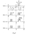
- Fig. 5 is a time chart for explaining operations of the signal recording/reproducing systems employed in this video signal transmitting system, as shown in Figs. 3 and 4.
- a signal recording system 20 related to the video signal transmitting system according to the present invention is provided at a preceding stage of the well-known VTR recording system 21.
- the signal recording system 20 is arranged by an inserting circuit20a, an identification (ID) signal line detecting circuit 20b, an identification signal (ID) content detecting circuit 20c, an insertion signal generating circuit 20d.
- Reference numeral 22 indicates a video signal input terminal for inputting a video signal "e" indicated in Fig. 5(A).
- the video signal "e" entered into the video signal input terminal 22 is supplied to the inserting circuit 20a, and the ID signal line detecting circuit 20b, and the sync separating circuit 20e, respectively.
- the inserting circuit 20a inserts (rewrites) a replicated ID signal "ee"' (namely, an ID signal identical to the ID signal "ee") supplied from the insertion signal generating circuit 20d into the effective picture portion "e l " of the (n-1)th line of the video signal "e” during either a subsequent (one frame after) video frame period, or a horizontal line immediately preceding the (n) th line in the subsequent video field orframe.
- the inserting circuit 20a may output a video signal "f' (shown in Fig.
- the ID signal line detecting circuit 20b detects the ID signal "ee” of the (n)th line of the video signal “e” in synchronization with commencement of the counting “n” times the horizontal sync signal “e” in the sync separating circuit 20e, in response to a counting signal derived from the counter circuit 20f. Then, the ID signal line detecting circuit 20b outputs the ID signal "ee” of the (n)th line of the video signal "e” to the ID signal content detecting circuit 20c.
- the ID signal content detecting circuit 20c detects the data content of the ID signal "ee” by comparing the respective data in an ID signal table built therein, with the data of the supplied ID signal "ee”, and outputs this detected signal through an ID signal writing device (not shown in detail) to the insertion signal generating circuit 20d, and furthermore outputs this detected signal to a display device (not shown either) provided as required.
- a user can confirm the respective video mode conditions of currently reproducing video signal by observing the displayed content on the display device.
- the user may change the content by manipulating the above-explained ID signal writing device. Then, this changed signal may be supplied to the insertion signal generating circuit 20d.
- the insertion signal generating circuit 20d generates a replicated ID signal for one horizontal scanning period based upon the output signal supplied via the ID signal writing device circuit 20c. Then, the insertion signal generating circuit 20d outputs this replicated ID signal to the above-described inserting circuit 20a.
- a replicated ID signal identical to the ID signal as "ee" is generated.
- the inserting circuit 20a can output such a video signal "e” during the current video frame period, in which the ID signal “ee” is inserted into only the effective picture portion of the (n)th line of the vertical blanking period, and also can output such a video signal "f' during the subsequent video frame period, in which-the ID signals "ee”' and “ee” are inserted into the respective effective picture. portions of the (n-1)th line and the (n)th line of the vertical blanking period.
- video signals "e” and “f' belong to the luminance (Y) signal produced by Y/C-separating the composite video signal
- these video signals are frequency-multiplexed with the carrier chrominance signal derived from the well-known VTR chrominance signal recording system (mainly composed of an automatic color control (ACC) circuit, a frequency conversion circuit, and a low-pass filter circuit) after the video signals "e” and “f' have been processed in the well-known VTR luminance signal recording system (mainly composed of a pre-emphasis circuit,a clamp/clip circuit, a frequency modulating circuit, and a high-pass filtercircuit) employed on the VTR signal recording system 21.
- ACC automatic color control
- VTR luminance signal recording system mainly composed of a pre-emphasis circuit, a clamp/clip circuit, a frequency modulating circuit, and a high-pass filtercircuit
- this frequency-multiplexed signal is amplified by the recording amplifier
- the amplified signals are supplied to one pair of video heads (not shown in detail) mounted on a rotary drum (not shown either), so that this frequency-multiplexed video signal amplified by the recording amplifier is successively and continually recorded on the magnetic tape 1, as illustrated in Fig. 1.
- the signal reproducing system 23 related to the video signal transmitting system according to the present invention is provided in a post stage of a VTR signal reproducing system 24 having a well-known circuit arrangement, as represented in Fig. 4.
- This signal reproducing system 23 is composed of a 1H delay circuit 23a and a switch 23b.
- This signal reproducing system 23 is represented by a typical dropout compensating circuit as shown, but it can be in different circuit arrangement from the one shown in Fig. 4. In this regard, a dropout compensation circuit often employed in conventional VTRs can be utilized as is in place of the signal reproducing system 23.
- the signal reproducing system 23 shown in Fig. 4 can compensate for a loss (dropout) of the ID signal "ee” even when, as previously stated, either the scratch or the dropout occurs on the magnetic tape I while the VTR signal recorded on this magnetic tape 1 by the VTR signal recording system 21 is reproduced by the VTR signal reproducing system 24.
- This compensation is performed by using the replicated ID signal "ee”' inserted into the effective picture portion of the reproduced video signal in the (n-1)th line in the same video field period, as the ID signal "ee” for the (n)th line.
- the switch 23b for constituting the above-described signal reproducing system 23 is arranged by fixed contacts 23b1, 23b2 and a movable contact 23b3. and is operated by a dropout detection signal conventionally produced (will be explained later) in and outputted from the VTR signal reproducing system 24. That is, when a dropout occurs, the movable contact 23b3 is moved from the fixed contact 23b1 to the fixed contact 23b2.
- a television receiver 25 is capable of selecting the normal TV picture with the aspect ratio of 4:3 and the high-quality TV picture with the aspect ratio of 16:9, i.e., the picture size along the horizontal direction being longer than the picture size along the vertical direction.
- the magnetic tape 1 by the VTR signal recording system 21 indicated in Fig. 3, are reproduced by scanning the magnetic tape 1 with a pair of video heads, which are a part of the VTR signal reproducing system 24.
- This VTR signal reproducing system 24 has an arrangement similar to that of a well-known VTR signal reproducing system.
- the reproduction signal outputted from the video heads is amplified by a reproduction amplifier, and thereafter the amplified reproduction signal is supplied to a low-pass filter circuit (not shown in detail) and a high-pass filter circuit (not shown either) respectively.
- An output signal from the low-pass filter circuit is supplied to a well-known VTR chroma signal reproducing system (mainly composed of an equalizer amplifier circuit, a limiter circuit, a dropout detecting circuit, a dropout compensator a frequency demodulating circuit, and a de-emphasis circuit). It should be noted that all of these circuits are not shown in Fig. 4.
- the reproduced video signal "i" (namely, Y/C separated chroma signal and luminance signals or a composite video signal obtained by frequency-multiplexing them each other), is supplied from the VTR signal reproducing system 24 to a video input terminal (not shown) of the television receiver 25.
- An output terminal of this 1H delay circuit 23a is connected to the other fixed contact 23b2 of the switch 23b.
- the television receiver 25 detects the content of this substituted ID signal "ee”' inserted into the effective picture portion of the (n-1)th line, and can display the picture information of the reproduced video signal "i" with the desired aspect ratio in response to the detection result.
- the lost ID signal "ee” caused by the dropout can be compensated by utilizing the dropout compensating circuit, and also the picture can be stably reproduced with the desired aspect ratio defined by the ID signal "ee"' which is always stable.
- the content of the picture is rewritten in a unit of either a single field period, or a 1H (horizontal) scanning line period. however, this does not pose a practical problem, since the picture information related to the ID signal such as the aspect ratio is not frequently changed in a unit of a single field period.
- the present invention is applied to the provisional system of EIAJ CPX-1204 "Specifications and Transfer Method of Video Aspect Ratio Identification Signal" suitable to the NTSC television broadcasting system.
- the present invention is applicable to the "PAL plus” system (625/50/2:1 system) which is compatible with the standard PAL television broadcasting system and is similar and suitable in specifications to "Specifications and Transfer Method of Video Aspect Ratio Identification Signal".
- the identification signals are inserted to the 23rd horizontal line in place of the 20th line in the foregoing description, so that the 23rd line is regarded as the (n)th line in the "PAL plus” system. Accordingly, with employment of the video signal transmission system according to the present invention. it is readily possible to compensate for lost identification signals by utilizing the dropout detecting signal of the dropout compensating circuit employed in recent VTRs.
- the ID signals are inserted into a plurality of horizontal lines preferably as many as possible, as far as it does not disturb an operation of VTRs, within the vertical blanking period during the signal recording operation.
- the number of horizontal lines to be inserted with the ID signals in recording and to be detected by the ID signal line detecting circuit 20b shown in Fig. 3, is changed correspondingly with a prospective length of dropout duration.
- the ID signal inserted in the 21 st line which is unharmed is detected and outputted twice or more to substitute at least the lost ID signal in the 23rd horizontal lines.
- the 1 H delay circuit 23a in Fig. 4 may be made of memory device, so that such unharmed ID signal once detected is outputted repeatedly as many times as desired for coping with a longer dropout duration.
- the ID signal inserted in the 20th horizontal line which is unharmed may be used for the purpose.
- the following method utilizing a majority circuit may be used.
- ID signals are inserted into each of plural and consecutive horizontal lines in the vertical blanking period during the signal recording operation. And supposing one of the ID signals inserted in the four consecutive horizontal lines is lost in the signal reproducing operation, the four consecutive horizontal lines containing the ID signals are fed successively to a 3/4th majority circuit, as a result of detecting 3 unharmed ID signals out of four inputted horizontal lines, the remaining one line which lacks the ID signal is determined, this enables the signal reproducing system 23 to output repeatedly the same ID signals for the four consecutive horizontal lines including the one lacking the ID signal. Accordingly, by employing such majority circuit, the present system can cope with the case that one out of four consecutive lines is subjected to a dropout of ID signal.
- the above 3/4th majority circuit can not cope with the problem.
- the lines of two consecutive lost ID signals can be determined.
- the preceding majority circuit determines the 22nd line as defective, and compensate for it. as a result, the 19th to 22nd lines without a dropout of ID signal are forwarded to the succeeding majority circuit.
- the succeeding majority circuit determines the defective 23rd line (the significant line in the "PAL plus” system) out of the 20th to 23rd lines inputted thereto by using the unharmed 20th to 22nd(compensated in the pre-stage) lines as the majority.
- the defective but significant 23rd line can be determined and compensated.
- a 3/4th majority circuit is referred to as an example in the foregoing explanation, but other type of majority circuit can be used in the similar manner to determine the defective lines obviously.
- the video signal transmitting system of present invention allows to transmit a video signal reliably without a dropout of the ID signal which is initially inserted to an effective picture portion of a specific horizontal line of the video signal.
- the video signal transmitting system is for reliably transmitting a video signal having a specific horizontal line containing an effective picture portion, to which an original ID signal related to picture information of the video signal is inserted.
- the video signal transmitting system features that when a loss of the original ID signal occurs, the effective picture portion inserted with the original ID signal is rewritten (substituted) with the ID signal inserted in the line adjacent (preceding) to the specific horizontal line, which is identical to or related to the original ID signal.
- a lost ID signal may be compensated for even under such conditions that a continuous scratch on the tape is caused along a direction of tape travel by the VTR mechanism, or a dropout occurs during the signal reproducing operation.
- this ID signal is indicative of picture aspect ratio to instruct a TV receiver to display a picture accordingly, the TV receiver is assured to display the picture stably with the intended picture aspect ratio defined by thus protected ID signal.
- the identical ID signals are inserted respectively into a plurality of horizontal lines in the vertical blanking period during the recording operation, and when dropout or the like involving the specific horizontal line occurs during the reproducing operation, any one of the ID signals inserted into the plural horizontal lines which are not subjected to the dropout may substitute the ID signal in the specific horizontal line.
Landscapes
- Engineering & Computer Science (AREA)
- Multimedia (AREA)
- Signal Processing (AREA)
- Computer Graphics (AREA)
- Television Signal Processing For Recording (AREA)
- Television Systems (AREA)
- Closed-Circuit Television Systems (AREA)
Applications Claiming Priority (2)
| Application Number | Priority Date | Filing Date | Title |
|---|---|---|---|
| JP5112331A JPH06303586A (ja) | 1993-04-15 | 1993-04-15 | 映像信号伝送方法 |
| JP112331/93 | 1993-04-15 |
Publications (2)
| Publication Number | Publication Date |
|---|---|
| EP0620682A2 true EP0620682A2 (fr) | 1994-10-19 |
| EP0620682A3 EP0620682A3 (fr) | 1995-01-25 |
Family
ID=14584008
Family Applications (1)
| Application Number | Title | Priority Date | Filing Date |
|---|---|---|---|
| EP94302606A Withdrawn EP0620682A3 (fr) | 1993-04-15 | 1994-04-13 | Système de transmission d'un signal vidéo. |
Country Status (2)
| Country | Link |
|---|---|
| EP (1) | EP0620682A3 (fr) |
| JP (1) | JPH06303586A (fr) |
Cited By (1)
| Publication number | Priority date | Publication date | Assignee | Title |
|---|---|---|---|---|
| EP0827338A2 (fr) * | 1996-08-29 | 1998-03-04 | Sanyo Electric Co., Ltd. | Appareil pour multiplexer et pour lire un code |
Citations (2)
| Publication number | Priority date | Publication date | Assignee | Title |
|---|---|---|---|---|
| EP0507614A2 (fr) * | 1991-04-04 | 1992-10-07 | Sony Corporation | Appareil d'enregistrement et/ou de reproduction vidéo |
| EP0515014A1 (fr) * | 1991-05-20 | 1992-11-25 | Pioneer Electronic Corporation | Appareil pour l'enregistrement d'un signal d'information et appareil pour la reproduction du signal d'information |
Family Cites Families (1)
| Publication number | Priority date | Publication date | Assignee | Title |
|---|---|---|---|---|
| JPH01106683A (ja) * | 1987-10-20 | 1989-04-24 | Victor Co Of Japan Ltd | 情報記録媒体の再生方法 |
-
1993
- 1993-04-15 JP JP5112331A patent/JPH06303586A/ja active Pending
-
1994
- 1994-04-13 EP EP94302606A patent/EP0620682A3/fr not_active Withdrawn
Patent Citations (2)
| Publication number | Priority date | Publication date | Assignee | Title |
|---|---|---|---|---|
| EP0507614A2 (fr) * | 1991-04-04 | 1992-10-07 | Sony Corporation | Appareil d'enregistrement et/ou de reproduction vidéo |
| EP0515014A1 (fr) * | 1991-05-20 | 1992-11-25 | Pioneer Electronic Corporation | Appareil pour l'enregistrement d'un signal d'information et appareil pour la reproduction du signal d'information |
Non-Patent Citations (1)
| Title |
|---|
| PATENT ABSTRACTS OF JAPAN vol. 13, no. 348 (E-799) 4 August 1989 & JP-A-01 106 683 (VICTOR CO. OF JAPAN,LTD.) 24 April 1989 * |
Cited By (2)
| Publication number | Priority date | Publication date | Assignee | Title |
|---|---|---|---|---|
| EP0827338A2 (fr) * | 1996-08-29 | 1998-03-04 | Sanyo Electric Co., Ltd. | Appareil pour multiplexer et pour lire un code |
| EP0827338A3 (fr) * | 1996-08-29 | 1999-06-16 | Sanyo Electric Co., Ltd. | Appareil pour multiplexer et pour lire un code |
Also Published As
| Publication number | Publication date |
|---|---|
| JPH06303586A (ja) | 1994-10-28 |
| EP0620682A3 (fr) | 1995-01-25 |
Similar Documents
| Publication | Publication Date | Title |
|---|---|---|
| US5251041A (en) | Method and apparatus for modifying a video signal to inhibit unauthorized videotape recording and subsequent reproduction thereof | |
| EP0809399B1 (fr) | Dispositif pour la reproduction de signaux vidéo à compatibilité descendante avec une résolution verticale augmentée | |
| EP0558182B1 (fr) | Procédé et appareil pour la transmission des signaux vidéo avec des formats d'image différents | |
| EP0574892B1 (fr) | Dispositif pour l'enregistrement et la reproduction d'un signal vidéo numérique | |
| EP0682421A1 (fr) | Méthode pour la détection de la présence de transmissions multilingue dans un signal de son numérique | |
| US4398219A (en) | Switching apparatus for the recording and reproducing of PCM or video signals | |
| US5528433A (en) | Wide picture video recording/reproducing system | |
| US20070122122A1 (en) | Digital video signal recording/reproducing method and apparatus | |
| CA1083709A (fr) | Compensateur pour defaillance du signal | |
| US6421091B1 (en) | Data transmission apparatus for transmitting digital video and audio data between respective audio visual apparatuses, and method therefor | |
| EP0620682A2 (fr) | Système de transmission d'un signal vidéo | |
| US6453364B1 (en) | Information reproducing apparatus, information recording/reproducing apparatus and information selectively outputting apparatus, and electronic apparatus system thereof | |
| JPH0548995A (ja) | デイジタル磁気記録装置 | |
| US5589946A (en) | Video signal reproduction apparatus replacing drop-cut signal portions | |
| US5583648A (en) | Picture signal recording/reproducing method and apparatus for recording/reproducing a high-definition picture signal and a normal picture signal | |
| KR100255734B1 (ko) | 디지탈 비디오 테이프 레코더 | |
| JP3106451B2 (ja) | 映像信号記録制御方法 | |
| US5345271A (en) | Apparatus for separating vertical synchronizing signal components from image signals in video cassette recorder | |
| US6694088B1 (en) | Progressive scan video production system and magnetic recording/reproducing apparatus | |
| EP0616469A2 (fr) | Système de traitement de signal de télévision | |
| KR0172986B1 (ko) | 고선명도 화상신호 및 통상의 화상신호를 기록/재생하는 화상신호 기록/재생방법 및 장치 | |
| JP2751788B2 (ja) | データ伝送装置 | |
| KR930011429B1 (ko) | 영상기록 재생장치의 문자다중방송 재생시스템 | |
| JP3257016B2 (ja) | 付加情報抽出回路 | |
| JPH05219472A (ja) | 映像信号記録再生装置 |
Legal Events
| Date | Code | Title | Description |
|---|---|---|---|
| PUAI | Public reference made under article 153(3) epc to a published international application that has entered the european phase |
Free format text: ORIGINAL CODE: 0009012 |
|
| AK | Designated contracting states |
Kind code of ref document: A2 Designated state(s): DE FR GB |
|
| PUAL | Search report despatched |
Free format text: ORIGINAL CODE: 0009013 |
|
| AK | Designated contracting states |
Kind code of ref document: A3 Designated state(s): DE FR GB |
|
| 17P | Request for examination filed |
Effective date: 19950630 |
|
| 17Q | First examination report despatched |
Effective date: 19970804 |
|
| STAA | Information on the status of an ep patent application or granted ep patent |
Free format text: STATUS: THE APPLICATION IS DEEMED TO BE WITHDRAWN |
|
| 18D | Application deemed to be withdrawn |
Effective date: 19980217 |