EP0620631A1 - Système de contrôle pour appareils électroménagers - Google Patents
Système de contrôle pour appareils électroménagers Download PDFInfo
- Publication number
- EP0620631A1 EP0620631A1 EP94104383A EP94104383A EP0620631A1 EP 0620631 A1 EP0620631 A1 EP 0620631A1 EP 94104383 A EP94104383 A EP 94104383A EP 94104383 A EP94104383 A EP 94104383A EP 0620631 A1 EP0620631 A1 EP 0620631A1
- Authority
- EP
- European Patent Office
- Prior art keywords
- appliances
- central unit
- signals
- management system
- appliance
- Prior art date
- Legal status (The legal status is an assumption and is not a legal conclusion. Google has not performed a legal analysis and makes no representation as to the accuracy of the status listed.)
- Granted
Links
Images


Classifications
-
- G—PHYSICS
- G05—CONTROLLING; REGULATING
- G05B—CONTROL OR REGULATING SYSTEMS IN GENERAL; FUNCTIONAL ELEMENTS OF SUCH SYSTEMS; MONITORING OR TESTING ARRANGEMENTS FOR SUCH SYSTEMS OR ELEMENTS
- G05B19/00—Programme-control systems
- G05B19/02—Programme-control systems electric
- G05B19/04—Programme control other than numerical control, i.e. in sequence controllers or logic controllers
- G05B19/042—Programme control other than numerical control, i.e. in sequence controllers or logic controllers using digital processors
- G05B19/0421—Multiprocessor system
-
- H—ELECTRICITY
- H02—GENERATION; CONVERSION OR DISTRIBUTION OF ELECTRIC POWER
- H02J—CIRCUIT ARRANGEMENTS OR SYSTEMS FOR SUPPLYING OR DISTRIBUTING ELECTRIC POWER; SYSTEMS FOR STORING ELECTRIC ENERGY
- H02J13/00—Circuit arrangements for providing remote indication of network conditions, e.g. an instantaneous record of the open or closed condition of each circuitbreaker in the network; Circuit arrangements for providing remote control of switching means in a power distribution network, e.g. switching in and out of current consumers by using a pulse code signal carried by the network
- H02J13/00004—Circuit arrangements for providing remote indication of network conditions, e.g. an instantaneous record of the open or closed condition of each circuitbreaker in the network; Circuit arrangements for providing remote control of switching means in a power distribution network, e.g. switching in and out of current consumers by using a pulse code signal carried by the network characterised by the power network being locally controlled
-
- H—ELECTRICITY
- H02—GENERATION; CONVERSION OR DISTRIBUTION OF ELECTRIC POWER
- H02J—CIRCUIT ARRANGEMENTS OR SYSTEMS FOR SUPPLYING OR DISTRIBUTING ELECTRIC POWER; SYSTEMS FOR STORING ELECTRIC ENERGY
- H02J13/00—Circuit arrangements for providing remote indication of network conditions, e.g. an instantaneous record of the open or closed condition of each circuitbreaker in the network; Circuit arrangements for providing remote control of switching means in a power distribution network, e.g. switching in and out of current consumers by using a pulse code signal carried by the network
- H02J13/00006—Circuit arrangements for providing remote indication of network conditions, e.g. an instantaneous record of the open or closed condition of each circuitbreaker in the network; Circuit arrangements for providing remote control of switching means in a power distribution network, e.g. switching in and out of current consumers by using a pulse code signal carried by the network characterised by information or instructions transport means between the monitoring, controlling or managing units and monitored, controlled or operated power network element or electrical equipment
- H02J13/00019—Circuit arrangements for providing remote indication of network conditions, e.g. an instantaneous record of the open or closed condition of each circuitbreaker in the network; Circuit arrangements for providing remote control of switching means in a power distribution network, e.g. switching in and out of current consumers by using a pulse code signal carried by the network characterised by information or instructions transport means between the monitoring, controlling or managing units and monitored, controlled or operated power network element or electrical equipment using optical means
-
- H—ELECTRICITY
- H02—GENERATION; CONVERSION OR DISTRIBUTION OF ELECTRIC POWER
- H02J—CIRCUIT ARRANGEMENTS OR SYSTEMS FOR SUPPLYING OR DISTRIBUTING ELECTRIC POWER; SYSTEMS FOR STORING ELECTRIC ENERGY
- H02J3/00—Circuit arrangements for ac mains or ac distribution networks
- H02J3/12—Circuit arrangements for ac mains or ac distribution networks for adjusting voltage in ac networks by changing a characteristic of the network load
- H02J3/14—Circuit arrangements for ac mains or ac distribution networks for adjusting voltage in ac networks by changing a characteristic of the network load by switching loads on to, or off from, network, e.g. progressively balanced loading
-
- G—PHYSICS
- G05—CONTROLLING; REGULATING
- G05B—CONTROL OR REGULATING SYSTEMS IN GENERAL; FUNCTIONAL ELEMENTS OF SUCH SYSTEMS; MONITORING OR TESTING ARRANGEMENTS FOR SUCH SYSTEMS OR ELEMENTS
- G05B2219/00—Program-control systems
- G05B2219/20—Pc systems
- G05B2219/25—Pc structure of the system
- G05B2219/25187—Transmission of signals, medium, ultrasonic, radio
-
- G—PHYSICS
- G05—CONTROLLING; REGULATING
- G05B—CONTROL OR REGULATING SYSTEMS IN GENERAL; FUNCTIONAL ELEMENTS OF SUCH SYSTEMS; MONITORING OR TESTING ARRANGEMENTS FOR SUCH SYSTEMS OR ELEMENTS
- G05B2219/00—Program-control systems
- G05B2219/20—Pc systems
- G05B2219/25—Pc structure of the system
- G05B2219/25192—Infrared
-
- H—ELECTRICITY
- H02—GENERATION; CONVERSION OR DISTRIBUTION OF ELECTRIC POWER
- H02J—CIRCUIT ARRANGEMENTS OR SYSTEMS FOR SUPPLYING OR DISTRIBUTING ELECTRIC POWER; SYSTEMS FOR STORING ELECTRIC ENERGY
- H02J2310/00—The network for supplying or distributing electric power characterised by its spatial reach or by the load
- H02J2310/10—The network having a local or delimited stationary reach
- H02J2310/12—The local stationary network supplying a household or a building
- H02J2310/14—The load or loads being home appliances
-
- Y—GENERAL TAGGING OF NEW TECHNOLOGICAL DEVELOPMENTS; GENERAL TAGGING OF CROSS-SECTIONAL TECHNOLOGIES SPANNING OVER SEVERAL SECTIONS OF THE IPC; TECHNICAL SUBJECTS COVERED BY FORMER USPC CROSS-REFERENCE ART COLLECTIONS [XRACs] AND DIGESTS
- Y02—TECHNOLOGIES OR APPLICATIONS FOR MITIGATION OR ADAPTATION AGAINST CLIMATE CHANGE
- Y02B—CLIMATE CHANGE MITIGATION TECHNOLOGIES RELATED TO BUILDINGS, e.g. HOUSING, HOUSE APPLIANCES OR RELATED END-USER APPLICATIONS
- Y02B70/00—Technologies for an efficient end-user side electric power management and consumption
- Y02B70/30—Systems integrating technologies related to power network operation and communication or information technologies for improving the carbon footprint of the management of residential or tertiary loads, i.e. smart grids as climate change mitigation technology in the buildings sector, including also the last stages of power distribution and the control, monitoring or operating management systems at local level
- Y02B70/3225—Demand response systems, e.g. load shedding, peak shaving
-
- Y—GENERAL TAGGING OF NEW TECHNOLOGICAL DEVELOPMENTS; GENERAL TAGGING OF CROSS-SECTIONAL TECHNOLOGIES SPANNING OVER SEVERAL SECTIONS OF THE IPC; TECHNICAL SUBJECTS COVERED BY FORMER USPC CROSS-REFERENCE ART COLLECTIONS [XRACs] AND DIGESTS
- Y02—TECHNOLOGIES OR APPLICATIONS FOR MITIGATION OR ADAPTATION AGAINST CLIMATE CHANGE
- Y02B—CLIMATE CHANGE MITIGATION TECHNOLOGIES RELATED TO BUILDINGS, e.g. HOUSING, HOUSE APPLIANCES OR RELATED END-USER APPLICATIONS
- Y02B90/00—Enabling technologies or technologies with a potential or indirect contribution to GHG emissions mitigation
- Y02B90/20—Smart grids as enabling technology in buildings sector
-
- Y—GENERAL TAGGING OF NEW TECHNOLOGICAL DEVELOPMENTS; GENERAL TAGGING OF CROSS-SECTIONAL TECHNOLOGIES SPANNING OVER SEVERAL SECTIONS OF THE IPC; TECHNICAL SUBJECTS COVERED BY FORMER USPC CROSS-REFERENCE ART COLLECTIONS [XRACs] AND DIGESTS
- Y04—INFORMATION OR COMMUNICATION TECHNOLOGIES HAVING AN IMPACT ON OTHER TECHNOLOGY AREAS
- Y04S—SYSTEMS INTEGRATING TECHNOLOGIES RELATED TO POWER NETWORK OPERATION, COMMUNICATION OR INFORMATION TECHNOLOGIES FOR IMPROVING THE ELECTRICAL POWER GENERATION, TRANSMISSION, DISTRIBUTION, MANAGEMENT OR USAGE, i.e. SMART GRIDS
- Y04S20/00—Management or operation of end-user stationary applications or the last stages of power distribution; Controlling, monitoring or operating thereof
- Y04S20/20—End-user application control systems
- Y04S20/222—Demand response systems, e.g. load shedding, peak shaving
-
- Y—GENERAL TAGGING OF NEW TECHNOLOGICAL DEVELOPMENTS; GENERAL TAGGING OF CROSS-SECTIONAL TECHNOLOGIES SPANNING OVER SEVERAL SECTIONS OF THE IPC; TECHNICAL SUBJECTS COVERED BY FORMER USPC CROSS-REFERENCE ART COLLECTIONS [XRACs] AND DIGESTS
- Y04—INFORMATION OR COMMUNICATION TECHNOLOGIES HAVING AN IMPACT ON OTHER TECHNOLOGY AREAS
- Y04S—SYSTEMS INTEGRATING TECHNOLOGIES RELATED TO POWER NETWORK OPERATION, COMMUNICATION OR INFORMATION TECHNOLOGIES FOR IMPROVING THE ELECTRICAL POWER GENERATION, TRANSMISSION, DISTRIBUTION, MANAGEMENT OR USAGE, i.e. SMART GRIDS
- Y04S20/00—Management or operation of end-user stationary applications or the last stages of power distribution; Controlling, monitoring or operating thereof
- Y04S20/20—End-user application control systems
- Y04S20/242—Home appliances
Definitions
- the present invention relates to a system for automatically managing the power input to a plurality of domestic electric loads, so as to prevent the electric loads from causing excessive total power peaks to be absorbed.
- a number of solutions including a central control unit capable of driving a set of loads, connected to an electric power network, so as to distribute over the time the power supplied to the loads when a concurrent operation of the same loads would involve excessive peaks in the total power absorbed.
- the central unit comprises a computerized arrangement enabling a limited number of electric loads to be supplied concurrently, according to a predetermined priority sequence, so as to keep the total power consumption within a predetermined maximum value.
- the prior systems referred to above may bring about an important inconvenience in case a user at first actuates at least an appliance (e.g., a dishwasher) having lower priority and later on (e.g., while the dishwasher is heating up the wash water) operates an appliance (e.g., a cooking oven) having higher priority. At that time it may happen that, in order to shave a peak in the power absorbed, the automatic management system temporarily deenergizes the lower priority appliance. As a consequence, the previously heated water in the dishwasher cools down during such an interruption and must be heated again when the management system re-starts the dishwasher. The consequent energy loss should be apparent.
- an appliance e.g., a dishwasher
- later on e.g., while the dishwasher is heating up the wash water
- an appliance e.g., a cooking oven
- Another object of the invention is to provide a management system of the type mentioned above which can substantially avoid any energy loss.
- Yet another object of the invention is to provide a management system of the type mentioned above which is relatively simple and reliable, without the need to use additional wirings.
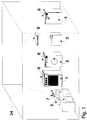
- the management system includes a plurality of domestic appliances for instance consisting of an electric cooking range (or oven) 1, a clothes washing machine 2, a refrigerator 3 and a dishwasher 4.
- the appliances are intended to be connected to an electric power supply network.
- the domestic appliances may comprise an air conditioner, a water heater, etc.
- the system comprises a central control unit 5, that is also supplied by the power network.
- each domestic appliance 1 to 4 is provided with a relevant infrared transceiver device 6, by means of which it is capable of communicating bidirectionally with the central unit 5, through a similar infrared transceiver device 7 provided in correspondence of the central unit itself.
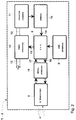
- each appliance 1 to 4 is of the type including an electronic programmer which substantially consists of control means 8 and a user interface 9 (a push-button panel, for example) by means of which various operative programmes of the appliance may be set and/or selected.
- operative programmes comprise one or more working phases of the operative elements of the appliance, forming relevant electric loads capable of absorbing a respective rated power from the supply network 10.
- the operative elements are diagrammatically shown at 11 in Figure 2 and are obviously different for each appliance.
- the operative elements 11 shall basically comprise a water-fill solenoid valve, a heating resistance, a motor for driving a rotatable drum, a discharge pump, etc.
- the control means 8 may for instance comprise a CPU based on a Motorola 68HC11, or NEC 78C10, microcontroller. According to the programme which may be selected, an output 13 of CPU 8 controls energization of the loads 11 through relevant power interfaces 12. A further input 14 of CPU 8 is driven by signals, from a plurality of sensors provided in the appliance, which are indicative of the values of relevant parameters of the programme possibly being carried out.
- the sensors are generally shown at 15 in Figure 2; in the washing machine 2, for example, they may comprise water-level sensors, temperature sensors, etc.
- the CPU 8 also includes an output 16 and an input 17 respectively connected, through a serial interface 18, which is preferably an asynchronous serial interface, to a corresponding input and a corresponding output of the associated transceiver 6.
- the latter may comprise a SHARP GP1U521X receiving module, and an array of SHARP GL537 transmitting photodiodes.
- each appliance 1 to 4 the control means 8 are arranged to control energization of the loads 11, through output 13, provided that an enabling signal is received at input 17. More particularly, enabling signals are transmitted by the central unit 5 and are encoded (using a binary code, for example) with information identifying corresponding appliances, so that they can only be received by the transceivers 6 associated with the appliances whose operation is enabled by the central unit 5.
- control means 8 of each appliance are so arranged as to generate at output 16, upon a user's demand for operation of the appliance through the interface 9, enquiry signals which are encoded (using a binary code, for example) with information identifying that appliance.
- enquiry signals are indicative of the power demanded by the operative elements 11 to perform any subsequent working phase provided in the selected programme.
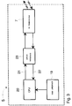
- the central control unit 5 basically comprises a CPU 20 which may be based, like the control means 8, on a Motorola 68HC11, or NEC 78C10 microprocessor. In a per se known manner, the CPU may be programmed through an interface 19, including for instance a push-button panel.
- the CPU 20 includes an output 21 and an input 22 respectively connected, through a serial interface 23, which is preferably an asynchronous serial interface, to a corresponding input and a corresponding output of the associated transceiver 7.
- a serial interface 23 which is preferably an asynchronous serial interface, to a corresponding input and a corresponding output of the associated transceiver 7.
- the latter may comprise a SHARP GP1U521X receiving module, and an array of SHARP GL537 transmitting photodiodes.
- the central unit 5 is capable of driving the appliances 1 to 4 with the said enabling signals, according to a priority sequence programmed through interface 19, so as to keep the total power concurrently absorbed by the appliances within a predetermined maximum value (e.g., 3 kW).
- the enabling signals are generated by CPU 20 at its output 21 and are transmitted to the transceivers 6 of the appliances 1 to 4 through the tranceiver 7.
- the control means 8 are enabled to energize the loads 11, through the power interfaces 12, according to the operative programme which has been selected through the push-button panel 9.
- the management system will tend to permit concurrent operation of more than one appliances 1 to 4 (those whose operation is demanded by a user) provided that the total power consumption will not exceed said maximum value.
- the central unit 5 transmits to the transceivers 6 enabling signals which are encoded so as to exclude operation of the appliances 1 to 4 having lower priority.
- central unit 5 when a user demands operation of an appliance 1 to 4 the latter transmits the said enquiry signals to the central unit 5 that are indicative of the power demanded by the appliance itself to carry out the next working phase of the selected operative programme.
- central unit 5 can determine, on the basis of the programmed priority sequence, which appliances will be able to work at the same time, during the concurrence of the relevant next working phases, with a total power consumption not exceeding the predetermined maximum value.
- central unit 5 whenever central unit 5 receives the enquiry signals it responds by driving with said enabling signals only those appliances that shall perform a working phase not causing an excessive total power consumption. If the total power consumption which would be involved during the concurrence of said working phases exceeds the maximum value, the central unit 5 temporarily excludes the appliances having lower priority from operation.
- the management system of the invention is not confined to enabling operation of the lower-priority appliances only when higher-priority appliances have terminated their operating cycles.
- the appliances temporarily excluded by the central unit 5 during given working phases of the higher-priority appliances can be energized, at least temporarily, during subsequent working phases of the higher-priority appliances in which a reduced power consumption is required.
- Such an operation is illustrated by way of example by the flow-chart shown in Figures 4 and 5 (relating to two appliances only) and advantageously permits the low-power working phases of the higher-priority appliances to be used to concurrently actuate even the lower-priority appliances possibly excluded in a former phase.
- the management system according to the invention is able to handle the power available on the supply network 10 in a "smart" manner, avoiding useless waiting periods in the operation of the lower-priority appliances.
- the oven 1 has to subsequently carry out a working phase involving lower power consumption (e.g., only a part of the heating elements of the oven are to be energized), it may happen that a total power demand not exceeding the predetermined maximum value is expected during the concurrence of the respective subsequent working phases of the appliances 1 and 2.
- the central unit 5 in this case enables concurrent operation of the two appliances until the said maximum power value is possibly exceeded.
- a period in which the oven 1 absorbs reduced power is used to supply the washing machine 2 with the remainder of the available power, without any need to first wait for the operative programme of the oven to terminate.
- the management system is capable of discontinuing operation of a lower-priority appliance 1 to 4, in compliance with the programmed priority sequence, only in given cases, that is, provided that such an interruption has no negative effects with regard to energy saving.
- Such negative effects would occur, for example, if in response to the enquiry signals from the appliances 1 and 2 the operation of the washing machine 2 would be discontinued, in order to limit the total power consumption, when the machine is completing a water heating phase. Obviously, deenergization of the washing machine at that time would bring about undesirable energy losses.
- the control means 8 are arranged to generate at output 16, preferably in a continuous manner, also encoded (for example in binary form) state signals.
- the state signals are indicative of the opportunity, if any, of interrupting the programme being carried out, where the total available power is insufficient.
- the state signals are transmitted by the transceiver 6 of the appliance to the transceiver 7 of the central unit, which accordingly may exclude from the programmed priority sequence the possibility of deenergizing the corresponding appliance which, in spite of its lower priority, has anyway to terminate the working phase being performed.
- the programmed priority sequence may be changed by the central unit 5 according to the state signals from the appliances 1 to 4. It should be apparent that in this way the management system is able to control operation of the appliances 1 to 4 in a particularly smart manner, thereby minimizing energy losses.
- the CPUs 8 and 20 in the appliances and central unit, respectively, may be programmed and arranged, in order to determine the correlation among the enquiry signals, state signals, enabling signals and priority sequence, in a number of different manners per se falling within the general knowledge of a man skilled in the art and not forming part of this invention.
- the transceivers 6 and 7 permit a bi-directional communication between the appliances 1 to 4 and the central unit 5 without requiring any additional wirings for interconnection thereof. Thanks to the transmission of the encoded signals in the form of infrared rays the whole system is also particularly reliable, in that, as is known, infrared transceiver arrangements are advantageously free from substantial disturbances.
- the transceivers 6 and 7 are preferably oriented as shown in Figure 1, so as to bi-directionally transmit the infrared signals through reflection thereof by means of a reference surface 24, which is preferably of light colour.
- a reference surface 24 may for instance consist of the ceiling of the room in which the appliances and the central unit are placed.
- the infrared rays extend in the room with a geometrical configuration which minimizes possible disturbances caused by persons or other objects moving in the room itself.
- the central unit 5 may be built in one of the household appliances, e.g. the oven 1, instead of being arranged in the form of a separate module.
- the central unit 5 shall be integrated with the programmer of that appliance, which shall not be provided with a relevant transceiver 6. The consequent structural simplification should be apparent.
Landscapes
- Engineering & Computer Science (AREA)
- Power Engineering (AREA)
- Physics & Mathematics (AREA)
- General Physics & Mathematics (AREA)
- Automation & Control Theory (AREA)
- Supply And Distribution Of Alternating Current (AREA)
- Remote Monitoring And Control Of Power-Distribution Networks (AREA)
- Selective Calling Equipment (AREA)
Applications Claiming Priority (2)
| Application Number | Priority Date | Filing Date | Title |
|---|---|---|---|
| IT93PN000026A IT1268517B1 (it) | 1993-04-15 | 1993-04-15 | Sistema per la gestione di carichi elettrici domestici |
| ITPN930026 | 1993-04-15 |
Publications (2)
| Publication Number | Publication Date |
|---|---|
| EP0620631A1 true EP0620631A1 (fr) | 1994-10-19 |
| EP0620631B1 EP0620631B1 (fr) | 1996-12-04 |
Family
ID=11394784
Family Applications (1)
| Application Number | Title | Priority Date | Filing Date |
|---|---|---|---|
| EP94104383A Expired - Lifetime EP0620631B1 (fr) | 1993-04-15 | 1994-03-21 | Système de contrÔle pour appareils électroménagers |
Country Status (4)
| Country | Link |
|---|---|
| EP (1) | EP0620631B1 (fr) |
| DE (1) | DE69401025T2 (fr) |
| ES (1) | ES2097565T3 (fr) |
| IT (1) | IT1268517B1 (fr) |
Cited By (43)
| Publication number | Priority date | Publication date | Assignee | Title |
|---|---|---|---|---|
| GB2289996A (en) * | 1994-06-02 | 1995-12-06 | Home Automation Ltd | Remote control of power supply to loads |
| DE19502786A1 (de) * | 1995-01-28 | 1996-08-08 | Daimler Benz Ag | Schaltungsanordnung und Verfahren zu gezielten Spannungsversorgung von an einem Versorgungsnetz angeschlossenen elektrischen Geräten |
| DE19530825A1 (de) * | 1995-08-22 | 1997-02-27 | Dieter Rupert Bruederl | Verfahren und Vorrichtung zur Energieoptimierung bei einem Energieverteilungssystem |
| EP0846991A1 (fr) * | 1996-12-04 | 1998-06-10 | Miele & Cie. GmbH & Co. | Dispositif centralisé de commande et de surveillance pour appareils ménagers avec unité d'affichage sans fil |
| WO1998050833A1 (fr) * | 1997-05-06 | 1998-11-12 | Gas Research Institute | Repeteur r.f. pour systeme automatise de gestion d'un ensemble residentiel |
| EP0903652A2 (fr) * | 1997-09-19 | 1999-03-24 | Siemens Aktiengesellschaft | Dispositif de commande et d'observation avec unité d'émetteur et récepteur à infrarouge |
| EP0903653A2 (fr) * | 1997-09-19 | 1999-03-24 | Siemens Aktiengesellschaft | Dispositif de commande et d'observation avec unité d'émetteur et récepteur à infrarouge |
| EP0913905A2 (fr) * | 1997-11-03 | 1999-05-06 | Voss GrossküchenSysteme GmbH | Méthode et dispositif pour limiter la consommation totale d'une pluralité de charges électriques d'un réseau électrique |
| EP0953890A2 (fr) * | 1998-04-27 | 1999-11-03 | AEG Hausgeräte GmbH | Appareil électroménager et sa méthode de commande |
| EP1037124A2 (fr) * | 1999-03-18 | 2000-09-20 | Wolfgang Rothengass | Appareil pour la commande d'un dispositif fonctionnel domestique |
| WO2001028068A1 (fr) * | 1999-10-13 | 2001-04-19 | Wrap S.P.A. | Systeme de surveillance et de commande d'un ensemble d'appareils menagers |
| WO2001057823A2 (fr) * | 2000-02-01 | 2001-08-09 | Domain Logix Corporation | Appareil et procede utilises pour la gestion d'outil web |
| EP1186694A2 (fr) * | 2000-09-11 | 2002-03-13 | Kabushiki Kaisha Toshiba | Commande d'un appareil de traitement du linge |
| DE10061871A1 (de) * | 2000-12-12 | 2002-06-27 | Testo Gmbh & Co Kg | Verfahren zur Steuerung oder Regelung des Energieflusses in einem aus mehreren Einzelmodulen zusammensteckbaren Messsystem |
| WO2003071366A1 (fr) * | 2002-02-18 | 2003-08-28 | Infineon Technologies Ag | Systeme de commande et procede pour faire fonctionner un dispositif d'emission/reception |
| EP1367685A1 (fr) * | 2002-05-31 | 2003-12-03 | Whirlpool Corporation | Système électronique pour la gestion de consommation d'énergie d'appareils |
| EP1441430A1 (fr) | 2003-01-21 | 2004-07-28 | Whirlpool Corporation | Procédé pour la gestion et la réduction de la demande de puissance d'appareils et de composants de ceux-ci, et système utilisant ce procédé |
| EP1640824A1 (fr) * | 2004-09-22 | 2006-03-29 | Electrolux Home Products Corporation N.V. | Appareil ménager avec fiches intégrées |
| WO2006049356A1 (fr) * | 2004-11-02 | 2006-05-11 | Lg Electronics, Inc. | Système de gestion de la consommation d'énergie domestique |
| US7155297B2 (en) | 2003-09-11 | 2006-12-26 | Siemens Aktiengesellschaft | Method to control a unit of a technical apparatus |
| WO2006089718A3 (fr) * | 2005-02-24 | 2007-01-25 | Abb Ltd | Gestion intelligente d'alimentation de verins |
| CN100362721C (zh) * | 2006-03-16 | 2008-01-16 | 钟挺 | 高效节能供电方法及控制系统 |
| US20080136581A1 (en) * | 2005-06-09 | 2008-06-12 | Whirlpool Corporation | smart current attenuator for energy conservation in appliances |
| US7403984B2 (en) | 2000-02-01 | 2008-07-22 | Asyst Technologies, Inc. | Automated tool management in a multi-protocol environment |
| US7561977B2 (en) | 2002-06-13 | 2009-07-14 | Whirlpool Corporation | Total home energy management system |
| US7619128B2 (en) | 2005-03-25 | 2009-11-17 | Exxonmobil Chemical Patents Inc. | Stabilizing catalyst activity during catalyst regeneration |
| US7705484B2 (en) | 2007-04-10 | 2010-04-27 | Whirlpool Corporation | Energy management system and method |
| EP2192457A1 (fr) * | 2008-11-28 | 2010-06-02 | Siemens Aktiengesellschaft | Elément d'automatisation pour une installation d'automatisation industrielle et procédé d'activation d'un état de fonctionnement |
| EP2194493A1 (fr) * | 2008-12-03 | 2010-06-09 | Whirlpool Corporation | Architecture de messagerie et système pour la gestion électronique de ressources |
| US7756963B2 (en) | 2001-07-05 | 2010-07-13 | PEER Intellectual Property, Inc. | Automated tool management in a multi-protocol environment |
| EP2251645A2 (fr) | 2009-05-12 | 2010-11-17 | Siemens Aktiengesellschaft | Procédé et système pour mesurer l'électricité décentralisée |
| US7873428B2 (en) | 2005-04-15 | 2011-01-18 | PEER Intellectual Property, Inc. | Automated job management |
| DE102009027800A1 (de) * | 2009-07-17 | 2011-01-27 | BSH Bosch und Siemens Hausgeräte GmbH | Haushaltsgerät mit einer Kommunikationseinrichtung, Gerätesystem und Verfahren zum Betreiben eines Haushaltsgeräts |
| WO2010128727A3 (fr) * | 2009-05-04 | 2011-08-25 | Lg Electronics Inc. | Appareil pour le traitement du linge et procédé de commande correspondant |
| US8027752B2 (en) | 2005-06-09 | 2011-09-27 | Whirlpool Corporation | Network for changing resource consumption in an appliance |
| US8073439B2 (en) | 2002-02-18 | 2011-12-06 | Infineon Technologies Ag | Control system and method for operating a transceiver |
| US8250163B2 (en) | 2005-06-09 | 2012-08-21 | Whirlpool Corporation | Smart coupling device |
| WO2013104767A1 (fr) * | 2012-01-13 | 2013-07-18 | Sony Corporation | Système de contrôle et procédé de contrôle de dispositifs électriques |
| US20130204449A1 (en) * | 2010-06-26 | 2013-08-08 | Lg Electronics Inc. | Network system |
| US8942835B2 (en) | 2011-06-16 | 2015-01-27 | Bsh Home Appliances Corporation | System and method of operating household appliances |
| EP2539990A4 (fr) * | 2006-05-18 | 2015-12-23 | Gridpoint Inc | Système modulaire de gestion de l'énergie |
| US9785140B2 (en) | 2000-02-01 | 2017-10-10 | Peer Intellectual Property Inc. | Multi-protocol multi-client equipment server |
| EP2523006A3 (fr) * | 2011-01-27 | 2018-06-20 | Samsung Electronics Co., Ltd. | Instrument électrique, appareil de gestion de puissance, système de gestion d'alimentation doté de celui-ci et procédé de contrôle correspondant |
Families Citing this family (7)
| Publication number | Priority date | Publication date | Assignee | Title |
|---|---|---|---|---|
| DE10208221A1 (de) * | 2002-02-26 | 2003-09-04 | Bsh Bosch Siemens Hausgeraete | Schnittstellenvorrichtung für ein Haushaltsgerät und Haushaltsgerät |
| DE10214794A1 (de) * | 2002-04-04 | 2004-01-08 | Alexander Kober | Überwachungseinrichtung für ein Haushaltsgerät und Verfahren zur Überwachung eines Haushaltsgerätes |
| DE102005032090A1 (de) * | 2005-07-08 | 2007-01-18 | BSH Bosch und Siemens Hausgeräte GmbH | Hausgerätevorrichtung mit einer Steuereinheit zum Steuern eines Programmablaufs |
| ES1067533Y (es) | 2008-03-17 | 2008-08-16 | Itw Espana Sa | Tapon obturador de orificios en chapas |
| DE102008043914A1 (de) * | 2008-11-20 | 2010-05-27 | BSH Bosch und Siemens Hausgeräte GmbH | System mit zwei Hausgeräten und Verfahren zum Energiemanagement eines derartigen Systems |
| ES2415758B1 (es) | 2011-06-20 | 2014-09-09 | Illinois Tool Works, Inc. | Tapón obturador de orificios |
| ES2761348A1 (es) | 2018-11-16 | 2020-05-19 | Illinois Tool Works | Elemento de sellado de orificios |
Citations (4)
| Publication number | Priority date | Publication date | Assignee | Title |
|---|---|---|---|---|
| EP0099043A2 (fr) * | 1982-07-15 | 1984-01-25 | Siemens Aktiengesellschaft | Système pour commander la consommation d'énergie électrique, de préférence pour l'usage domestique |
| EP0208597A1 (fr) * | 1985-07-05 | 1987-01-14 | Manufacture D'appareillage Electrique De Cahors | Adaptateur de puissance pour installations électriques, notamment domestiques |
| EP0466152A1 (fr) * | 1990-07-13 | 1992-01-15 | Moulinex | Dispositif de plusieurs émetteurs-récepteurs électriques montés dans un réseau de distribution d'énergie électrique |
| FR2672400A1 (fr) * | 1991-02-01 | 1992-08-07 | Euro Cp Sarl | Procede de gestion globale de l'energie electrique dans un reseau domotique. |
-
1993
- 1993-04-15 IT IT93PN000026A patent/IT1268517B1/it active IP Right Grant
-
1994
- 1994-03-21 DE DE69401025T patent/DE69401025T2/de not_active Expired - Lifetime
- 1994-03-21 ES ES94104383T patent/ES2097565T3/es not_active Expired - Lifetime
- 1994-03-21 EP EP94104383A patent/EP0620631B1/fr not_active Expired - Lifetime
Patent Citations (4)
| Publication number | Priority date | Publication date | Assignee | Title |
|---|---|---|---|---|
| EP0099043A2 (fr) * | 1982-07-15 | 1984-01-25 | Siemens Aktiengesellschaft | Système pour commander la consommation d'énergie électrique, de préférence pour l'usage domestique |
| EP0208597A1 (fr) * | 1985-07-05 | 1987-01-14 | Manufacture D'appareillage Electrique De Cahors | Adaptateur de puissance pour installations électriques, notamment domestiques |
| EP0466152A1 (fr) * | 1990-07-13 | 1992-01-15 | Moulinex | Dispositif de plusieurs émetteurs-récepteurs électriques montés dans un réseau de distribution d'énergie électrique |
| FR2672400A1 (fr) * | 1991-02-01 | 1992-08-07 | Euro Cp Sarl | Procede de gestion globale de l'energie electrique dans un reseau domotique. |
Cited By (69)
| Publication number | Priority date | Publication date | Assignee | Title |
|---|---|---|---|---|
| GB2289996B (en) * | 1994-06-02 | 1998-08-26 | Home Automation Ltd | Bus controlled electrical mains supply |
| GB2289996A (en) * | 1994-06-02 | 1995-12-06 | Home Automation Ltd | Remote control of power supply to loads |
| DE19502786A1 (de) * | 1995-01-28 | 1996-08-08 | Daimler Benz Ag | Schaltungsanordnung und Verfahren zu gezielten Spannungsversorgung von an einem Versorgungsnetz angeschlossenen elektrischen Geräten |
| DE19502786C2 (de) * | 1995-01-28 | 1997-02-20 | Daimler Benz Ag | Schaltungsanordnung und Verfahren zur gezielten Spannungsversorgung von an einem Versorgungsnetz angeschlossenen elektrischen Geräten |
| DE19530825C2 (de) * | 1995-08-22 | 1999-04-29 | Dieter Rupert Bruederl | Verfahren und Vorrichtung zur Energieoptimierung bei einem Energieverteilungssystem |
| DE19530825A1 (de) * | 1995-08-22 | 1997-02-27 | Dieter Rupert Bruederl | Verfahren und Vorrichtung zur Energieoptimierung bei einem Energieverteilungssystem |
| EP0846991A1 (fr) * | 1996-12-04 | 1998-06-10 | Miele & Cie. GmbH & Co. | Dispositif centralisé de commande et de surveillance pour appareils ménagers avec unité d'affichage sans fil |
| US6061604A (en) * | 1997-05-06 | 2000-05-09 | Gas Research Institute | RF base repeater for automated residence management system |
| WO1998050833A1 (fr) * | 1997-05-06 | 1998-11-12 | Gas Research Institute | Repeteur r.f. pour systeme automatise de gestion d'un ensemble residentiel |
| EP0903652A2 (fr) * | 1997-09-19 | 1999-03-24 | Siemens Aktiengesellschaft | Dispositif de commande et d'observation avec unité d'émetteur et récepteur à infrarouge |
| EP0903653A2 (fr) * | 1997-09-19 | 1999-03-24 | Siemens Aktiengesellschaft | Dispositif de commande et d'observation avec unité d'émetteur et récepteur à infrarouge |
| EP0903653A3 (fr) * | 1997-09-19 | 1999-12-15 | Siemens Aktiengesellschaft | Dispositif de commande et d'observation avec unité d'émetteur et récepteur à infrarouge |
| EP0903652A3 (fr) * | 1997-09-19 | 1999-12-15 | Siemens Aktiengesellschaft | Dispositif de commande et d'observation avec unité d'émetteur et récepteur à infrarouge |
| EP0913905A2 (fr) * | 1997-11-03 | 1999-05-06 | Voss GrossküchenSysteme GmbH | Méthode et dispositif pour limiter la consommation totale d'une pluralité de charges électriques d'un réseau électrique |
| EP0913905A3 (fr) * | 1997-11-03 | 1999-12-08 | Voss GrossküchenSysteme GmbH | Méthode et dispositif pour limiter la consommation totale d'une pluralité de charges électriques d'un réseau électrique |
| EP0953890A2 (fr) * | 1998-04-27 | 1999-11-03 | AEG Hausgeräte GmbH | Appareil électroménager et sa méthode de commande |
| EP0953890A3 (fr) * | 1998-04-27 | 2001-10-17 | AEG Hausgeräte GmbH | Appareil électroménager et sa méthode de commande |
| EP1037124A2 (fr) * | 1999-03-18 | 2000-09-20 | Wolfgang Rothengass | Appareil pour la commande d'un dispositif fonctionnel domestique |
| EP1037124A3 (fr) * | 1999-03-18 | 2000-10-18 | Wolfgang Rothengass | Appareil pour la commande d'un dispositif fonctionnel domestique |
| WO2001028068A1 (fr) * | 1999-10-13 | 2001-04-19 | Wrap S.P.A. | Systeme de surveillance et de commande d'un ensemble d'appareils menagers |
| US7363031B1 (en) | 1999-10-13 | 2008-04-22 | Indesit Company S.P.A. | System for monitoring and controlling a set of household appliances |
| US7403984B2 (en) | 2000-02-01 | 2008-07-22 | Asyst Technologies, Inc. | Automated tool management in a multi-protocol environment |
| US10007256B2 (en) | 2000-02-01 | 2018-06-26 | Peer Intellectual Property Inc. | Multi-protocol multi-client equipment server |
| US8028049B1 (en) | 2000-02-01 | 2011-09-27 | Peer Intellectual Property Inc. | Apparatus and method for web-based tool management |
| WO2001057823A2 (fr) * | 2000-02-01 | 2001-08-09 | Domain Logix Corporation | Appareil et procede utilises pour la gestion d'outil web |
| WO2001057823A3 (fr) * | 2000-02-01 | 2002-02-07 | Domain Logix Corp | Appareil et procede utilises pour la gestion d'outil web |
| US9785140B2 (en) | 2000-02-01 | 2017-10-10 | Peer Intellectual Property Inc. | Multi-protocol multi-client equipment server |
| EP1186694A3 (fr) * | 2000-09-11 | 2004-04-14 | Kabushiki Kaisha Toshiba | Commande d'un appareil de traitement du linge |
| EP1186694A2 (fr) * | 2000-09-11 | 2002-03-13 | Kabushiki Kaisha Toshiba | Commande d'un appareil de traitement du linge |
| DE10061871A1 (de) * | 2000-12-12 | 2002-06-27 | Testo Gmbh & Co Kg | Verfahren zur Steuerung oder Regelung des Energieflusses in einem aus mehreren Einzelmodulen zusammensteckbaren Messsystem |
| US7756963B2 (en) | 2001-07-05 | 2010-07-13 | PEER Intellectual Property, Inc. | Automated tool management in a multi-protocol environment |
| US8073439B2 (en) | 2002-02-18 | 2011-12-06 | Infineon Technologies Ag | Control system and method for operating a transceiver |
| WO2003071366A1 (fr) * | 2002-02-18 | 2003-08-28 | Infineon Technologies Ag | Systeme de commande et procede pour faire fonctionner un dispositif d'emission/reception |
| US9837820B2 (en) | 2002-05-31 | 2017-12-05 | Whirlpool Corporation | Electronic system for power consumption management of appliances |
| EP1367685A1 (fr) * | 2002-05-31 | 2003-12-03 | Whirlpool Corporation | Système électronique pour la gestion de consommation d'énergie d'appareils |
| US7561977B2 (en) | 2002-06-13 | 2009-07-14 | Whirlpool Corporation | Total home energy management system |
| EP1441430A1 (fr) | 2003-01-21 | 2004-07-28 | Whirlpool Corporation | Procédé pour la gestion et la réduction de la demande de puissance d'appareils et de composants de ceux-ci, et système utilisant ce procédé |
| DE10342014B4 (de) * | 2003-09-11 | 2012-08-30 | Siemens Ag | Verfahren zum Ansteuern einer Einheit einer technischen Vorrichtung |
| US7155297B2 (en) | 2003-09-11 | 2006-12-26 | Siemens Aktiengesellschaft | Method to control a unit of a technical apparatus |
| EP1640824A1 (fr) * | 2004-09-22 | 2006-03-29 | Electrolux Home Products Corporation N.V. | Appareil ménager avec fiches intégrées |
| WO2006049356A1 (fr) * | 2004-11-02 | 2006-05-11 | Lg Electronics, Inc. | Système de gestion de la consommation d'énergie domestique |
| US7446491B2 (en) | 2005-02-24 | 2008-11-04 | Abb Ltd. | Intelligent power management for actuators |
| WO2006089718A3 (fr) * | 2005-02-24 | 2007-01-25 | Abb Ltd | Gestion intelligente d'alimentation de verins |
| CN101128783B (zh) * | 2005-02-24 | 2011-12-14 | Abb有限公司 | 用于致动器的智能电源管理 |
| US7619128B2 (en) | 2005-03-25 | 2009-11-17 | Exxonmobil Chemical Patents Inc. | Stabilizing catalyst activity during catalyst regeneration |
| US7687675B2 (en) | 2005-03-25 | 2010-03-30 | Exxonmobil Chemical Patents Inc. | Stabilizing catalyst activity during catalyst regeneration |
| US7873428B2 (en) | 2005-04-15 | 2011-01-18 | PEER Intellectual Property, Inc. | Automated job management |
| US8027752B2 (en) | 2005-06-09 | 2011-09-27 | Whirlpool Corporation | Network for changing resource consumption in an appliance |
| US8250163B2 (en) | 2005-06-09 | 2012-08-21 | Whirlpool Corporation | Smart coupling device |
| US20080136581A1 (en) * | 2005-06-09 | 2008-06-12 | Whirlpool Corporation | smart current attenuator for energy conservation in appliances |
| US8615332B2 (en) * | 2005-06-09 | 2013-12-24 | Whirlpool Corporation | Smart current attenuator for energy conservation in appliances |
| CN100362721C (zh) * | 2006-03-16 | 2008-01-16 | 钟挺 | 高效节能供电方法及控制系统 |
| EP2539990A4 (fr) * | 2006-05-18 | 2015-12-23 | Gridpoint Inc | Système modulaire de gestion de l'énergie |
| EP3439141A1 (fr) * | 2006-05-18 | 2019-02-06 | Gridpoint, Inc. | Système modulaire de gestion de l'énergie |
| US7705484B2 (en) | 2007-04-10 | 2010-04-27 | Whirlpool Corporation | Energy management system and method |
| EP2192457A1 (fr) * | 2008-11-28 | 2010-06-02 | Siemens Aktiengesellschaft | Elément d'automatisation pour une installation d'automatisation industrielle et procédé d'activation d'un état de fonctionnement |
| EP2194493A1 (fr) * | 2008-12-03 | 2010-06-09 | Whirlpool Corporation | Architecture de messagerie et système pour la gestion électronique de ressources |
| US9665838B2 (en) | 2008-12-03 | 2017-05-30 | Whirlpool Corporation | Messaging architecture and system for electronic management of resources |
| WO2010128727A3 (fr) * | 2009-05-04 | 2011-08-25 | Lg Electronics Inc. | Appareil pour le traitement du linge et procédé de commande correspondant |
| EP2251645A2 (fr) | 2009-05-12 | 2010-11-17 | Siemens Aktiengesellschaft | Procédé et système pour mesurer l'électricité décentralisée |
| EP2905580A1 (fr) | 2009-05-12 | 2015-08-12 | France Brevets | Procédé et système pour mesurer l'électricité décentralisée |
| EP2251645A3 (fr) * | 2009-05-12 | 2012-06-06 | Siemens Aktiengesellschaft | Procédé et système pour mesurer l'électricité décentralisée |
| US9270115B2 (en) | 2009-07-17 | 2016-02-23 | Bsh Hausgeraete Gmbh | Domestic appliance comprising a communication unit, system of appliances and method for operating a domestic appliance |
| DE102009027800A1 (de) * | 2009-07-17 | 2011-01-27 | BSH Bosch und Siemens Hausgeräte GmbH | Haushaltsgerät mit einer Kommunikationseinrichtung, Gerätesystem und Verfahren zum Betreiben eines Haushaltsgeräts |
| US20130204449A1 (en) * | 2010-06-26 | 2013-08-08 | Lg Electronics Inc. | Network system |
| US10296989B2 (en) | 2010-06-26 | 2019-05-21 | Lg Electronics Inc. | Network system |
| EP2523006A3 (fr) * | 2011-01-27 | 2018-06-20 | Samsung Electronics Co., Ltd. | Instrument électrique, appareil de gestion de puissance, système de gestion d'alimentation doté de celui-ci et procédé de contrôle correspondant |
| US8942835B2 (en) | 2011-06-16 | 2015-01-27 | Bsh Home Appliances Corporation | System and method of operating household appliances |
| WO2013104767A1 (fr) * | 2012-01-13 | 2013-07-18 | Sony Corporation | Système de contrôle et procédé de contrôle de dispositifs électriques |
Also Published As
| Publication number | Publication date |
|---|---|
| DE69401025D1 (de) | 1997-01-16 |
| DE69401025T2 (de) | 1997-05-28 |
| ES2097565T3 (es) | 1997-04-01 |
| ITPN930026A1 (it) | 1994-10-15 |
| EP0620631B1 (fr) | 1996-12-04 |
| IT1268517B1 (it) | 1997-03-04 |
| ITPN930026A0 (it) | 1993-04-15 |
Similar Documents
| Publication | Publication Date | Title |
|---|---|---|
| EP0620631B1 (fr) | Système de contrÔle pour appareils électroménagers | |
| US6961642B2 (en) | System and method for reducing an instantaneous load in an appliance | |
| EP0953167B1 (fr) | Dispositif servant a commander un appareil electromenager | |
| US7884498B2 (en) | Method and arrangement for the energy-saving operation of dishwashers | |
| CN1182287C (zh) | 洗衣系统 | |
| EP1698725B2 (fr) | Ensemble d'appareils ménagers à fonctionnement intégré | |
| AU2010322810B8 (en) | Network system for a component | |
| US5436510A (en) | Method and a system for globally managing electric power in a network within a dwelling or the like | |
| US8190302B2 (en) | Load shedding system for an electromechanically controlled oven | |
| KR20090041003A (ko) | 세탁기 | |
| EP2202465A2 (fr) | Four pour cuire des aliments | |
| US20060117491A1 (en) | Controller effectively controlling the power for a washing machine or a dryer, and a method for doing the same | |
| US20010039460A1 (en) | Control system for a household appliance | |
| CN101994226A (zh) | 洗衣机及其控制方法 | |
| US20130289753A1 (en) | Method and apparatus for operating a domestic appliance and domestic appliance | |
| US20140303801A1 (en) | Network system | |
| EP2587727A2 (fr) | Système réseau | |
| AU679299B2 (en) | Electronic defrost controller with fan delay and drip time modes | |
| EP0356662A2 (fr) | Dispositif pour sélectionner les cycles d'opérations pour appareils électro-ménagers, en particulier lave-linge et/ou sèche-linge, cuisinières et appareils similaires | |
| EP2587445B1 (fr) | Système de réseau | |
| US5467263A (en) | Process for designating a distant functional object in a circuit, and functional units and installation pertaining thereto | |
| EP3544177B1 (fr) | Utilisation de l'énergie électrique produit par un système photovoltaïque domestique pour alimenter électriquement des appareils électriques commandés à distance | |
| EP0866160B1 (fr) | Procédé de lavage et machine à laver utilisant ce procédé | |
| GB2188799A (en) | Control system for electric power distribution | |
| WO1995016066A1 (fr) | Appareil electromenager de lavage et/ou de sechage a l'aide d'eau chaude provenant d'une installation de chauffage central et circulant dans des serpentins |
Legal Events
| Date | Code | Title | Description |
|---|---|---|---|
| PUAI | Public reference made under article 153(3) epc to a published international application that has entered the european phase |
Free format text: ORIGINAL CODE: 0009012 |
|
| AK | Designated contracting states |
Kind code of ref document: A1 Designated state(s): DE ES FR GB IT SE |
|
| 17P | Request for examination filed |
Effective date: 19950302 |
|
| 17Q | First examination report despatched |
Effective date: 19951201 |
|
| GRAG | Despatch of communication of intention to grant |
Free format text: ORIGINAL CODE: EPIDOS AGRA |
|
| GRAH | Despatch of communication of intention to grant a patent |
Free format text: ORIGINAL CODE: EPIDOS IGRA |
|
| ITF | It: translation for a ep patent filed |
Owner name: PROPRIA PROTEZIONE PROPR. IND. |
|
| GRAH | Despatch of communication of intention to grant a patent |
Free format text: ORIGINAL CODE: EPIDOS IGRA |
|
| GRAA | (expected) grant |
Free format text: ORIGINAL CODE: 0009210 |
|
| AK | Designated contracting states |
Kind code of ref document: B1 Designated state(s): DE ES FR GB IT SE |
|
| RIN1 | Information on inventor provided before grant (corrected) |
Inventor name: DIODATO, CLAUDIO Inventor name: RUGO, ANNA |
|
| REF | Corresponds to: |
Ref document number: 69401025 Country of ref document: DE Date of ref document: 19970116 |
|
| ET | Fr: translation filed | ||
| REG | Reference to a national code |
Ref country code: ES Ref legal event code: FG2A Ref document number: 2097565 Country of ref document: ES Kind code of ref document: T3 |
|
| PLBE | No opposition filed within time limit |
Free format text: ORIGINAL CODE: 0009261 |
|
| STAA | Information on the status of an ep patent application or granted ep patent |
Free format text: STATUS: NO OPPOSITION FILED WITHIN TIME LIMIT |
|
| 26N | No opposition filed | ||
| REG | Reference to a national code |
Ref country code: GB Ref legal event code: IF02 |
|
| PGFP | Annual fee paid to national office [announced via postgrant information from national office to epo] |
Ref country code: SE Payment date: 20110314 Year of fee payment: 18 Ref country code: FR Payment date: 20110404 Year of fee payment: 18 |
|
| PGFP | Annual fee paid to national office [announced via postgrant information from national office to epo] |
Ref country code: ES Payment date: 20110322 Year of fee payment: 18 Ref country code: GB Payment date: 20110321 Year of fee payment: 18 |
|
| PGFP | Annual fee paid to national office [announced via postgrant information from national office to epo] |
Ref country code: IT Payment date: 20120329 Year of fee payment: 19 |
|
| REG | Reference to a national code |
Ref country code: SE Ref legal event code: EUG |
|
| PG25 | Lapsed in a contracting state [announced via postgrant information from national office to epo] |
Ref country code: SE Free format text: LAPSE BECAUSE OF NON-PAYMENT OF DUE FEES Effective date: 20120322 |
|
| GBPC | Gb: european patent ceased through non-payment of renewal fee |
Effective date: 20120321 |
|
| REG | Reference to a national code |
Ref country code: FR Ref legal event code: ST Effective date: 20121130 |
|
| PG25 | Lapsed in a contracting state [announced via postgrant information from national office to epo] |
Ref country code: FR Free format text: LAPSE BECAUSE OF NON-PAYMENT OF DUE FEES Effective date: 20120402 Ref country code: GB Free format text: LAPSE BECAUSE OF NON-PAYMENT OF DUE FEES Effective date: 20120321 |
|
| PGFP | Annual fee paid to national office [announced via postgrant information from national office to epo] |
Ref country code: DE Payment date: 20130321 Year of fee payment: 20 |
|
| REG | Reference to a national code |
Ref country code: ES Ref legal event code: FD2A Effective date: 20130710 |
|
| PG25 | Lapsed in a contracting state [announced via postgrant information from national office to epo] |
Ref country code: ES Free format text: LAPSE BECAUSE OF NON-PAYMENT OF DUE FEES Effective date: 20120322 |
|
| REG | Reference to a national code |
Ref country code: DE Ref legal event code: R071 Ref document number: 69401025 Country of ref document: DE |
|
| REG | Reference to a national code |
Ref country code: DE Ref legal event code: R071 Ref document number: 69401025 Country of ref document: DE |
|
| PG25 | Lapsed in a contracting state [announced via postgrant information from national office to epo] |
Ref country code: DE Free format text: LAPSE BECAUSE OF EXPIRATION OF PROTECTION Effective date: 20140322 |