EP0620342B1 - Bolt for locks, particularly for panic-safe locks for double doors - Google Patents
Bolt for locks, particularly for panic-safe locks for double doors Download PDFInfo
- Publication number
- EP0620342B1 EP0620342B1 EP94104427A EP94104427A EP0620342B1 EP 0620342 B1 EP0620342 B1 EP 0620342B1 EP 94104427 A EP94104427 A EP 94104427A EP 94104427 A EP94104427 A EP 94104427A EP 0620342 B1 EP0620342 B1 EP 0620342B1
- Authority
- EP
- European Patent Office
- Prior art keywords
- bolt
- lock
- plate
- sliding plate
- lug
- Prior art date
- Legal status (The legal status is an assumption and is not a legal conclusion. Google has not performed a legal analysis and makes no representation as to the accuracy of the status listed.)
- Expired - Lifetime
Links
- 230000005540 biological transmission Effects 0.000 claims description 2
- 230000004308 accommodation Effects 0.000 claims 1
- 230000014759 maintenance of location Effects 0.000 claims 1
- 230000000717 retained effect Effects 0.000 description 3
- 230000006835 compression Effects 0.000 description 1
- 238000007906 compression Methods 0.000 description 1
- 230000000670 limiting effect Effects 0.000 description 1
Images

Classifications
-
- E—FIXED CONSTRUCTIONS
- E05—LOCKS; KEYS; WINDOW OR DOOR FITTINGS; SAFES
- E05B—LOCKS; ACCESSORIES THEREFOR; HANDCUFFS
- E05B59/00—Locks with latches separate from the lock-bolts or with a plurality of latches or lock-bolts
-
- E—FIXED CONSTRUCTIONS
- E05—LOCKS; KEYS; WINDOW OR DOOR FITTINGS; SAFES
- E05C—BOLTS OR FASTENING DEVICES FOR WINGS, SPECIALLY FOR DOORS OR WINDOWS
- E05C7/00—Fastening devices specially adapted for two wings
- E05C7/04—Fastening devices specially adapted for two wings for wings which abut when closed
-
- E—FIXED CONSTRUCTIONS
- E05—LOCKS; KEYS; WINDOW OR DOOR FITTINGS; SAFES
- E05B—LOCKS; ACCESSORIES THEREFOR; HANDCUFFS
- E05B65/00—Locks or fastenings for special use
- E05B65/10—Locks or fastenings for special use for panic or emergency doors
-
- E—FIXED CONSTRUCTIONS
- E05—LOCKS; KEYS; WINDOW OR DOOR FITTINGS; SAFES
- E05B—LOCKS; ACCESSORIES THEREFOR; HANDCUFFS
- E05B65/00—Locks or fastenings for special use
- E05B65/10—Locks or fastenings for special use for panic or emergency doors
- E05B65/1086—Locks with panic function, e.g. allowing opening from the inside without a ley even when locked from the outside
-
- E—FIXED CONSTRUCTIONS
- E05—LOCKS; KEYS; WINDOW OR DOOR FITTINGS; SAFES
- E05C—BOLTS OR FASTENING DEVICES FOR WINGS, SPECIALLY FOR DOORS OR WINDOWS
- E05C1/00—Fastening devices with bolts moving rectilinearly
- E05C1/02—Fastening devices with bolts moving rectilinearly without latching action
- E05C1/06—Fastening devices with bolts moving rectilinearly without latching action with operating handle or equivalent member moving otherwise than rigidly with the bolt
Definitions
- the present invention relates to a bolt for locks, particularly for panic-safe locks for double doors.
- door A In double doors, used as emergency doors, both doors open outward, and the door normally used to enter and to exit (hereinafter termed door A) is provided with a panicsafe lock having a spring latch and a bolt and designed so that the spring latch and the bolt can be moved simultaneously into their release position by operating the handle.
- door B acts as lock stile for door A and has an upper catch and a lower catch which are connected by means of rods to a so-called panic-safe strike lock actuatable by means of a handle of its own.
- the technical aim of the present invention is to provide a bolt including a release mechanism that is designed so that it can be activated only when the bolt is inserted in the respective selvage of the strike lock, so as to ensure maximum security against break-in attempts.
- the invention provides a bolt for a lock, particularly of the panic-safe type, which is installed in one door of a double door and is operatively associated with a strike lock installed in the other door, characterized in that it comprises a flat sliding plate accommodated in a seat of the bolt and guided, against the biasing action of elastic transmission means, at right angles to the sliding direction of said bolt, said sliding plate having a lug for abutment against a fixed element of the lock when the bolt is engaged in the strike lock, a slider being furthermore provided which is guided in said bolt parallel to the sliding direction of said bolt and has a tang protruding frontally from the bolt, said slider cooperating with said sliding plate so that when the bolt is engaged within the strike lock, the release action produced on the tang by means of the strike lock causes the slider to move the sliding plate into a position in which said lug does not abut against said fixed element, allowing retraction of the bolt into the lock due to the release action.
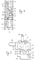
- the reference numeral 1 designates the faceplate of the casing of a panic-safe lock, in which there is a rectangular opening 2 through which the bolt 3 protrudes outside.
- the bolt 3 is guided not only in the opening 2 but also in the sliding direction A by a plate 4 the opposite ends whereof are fixed in the rear plate 5 and in the covering plate 6, which close the sides of the casing.
- the plate 4 slidingly engages a notch 7 which is open on the rear edge 8 of the bolt 3 and extends toward the front edge 9 along the direction A.
- a laminar seat 10 is formed in the bolt 3 on the plane thereof and is open toward the rear edge 8.
- the seat 10 is furthermore open upward, where it forms an opening 11, and downward, where it forms a shoulder 12 and a recess 13. Below the shoulder 12 there is a tooth 14 protruding downward and suitable to cooperate with the tumbler of the bolt actuation cylinder 25 which is described hereinafter.
- An extension 15 rises from the upper edge of the bolt, and a seat 16 is formed therein for a spring 17 the upper end of which is retained against a short pin 18 driven through a hole 19 of the extension.
- the spring 17 acts by compression on a flat sliding plate 20 accommodated in the seat 10.
- the sliding plate 20 is substantially rectangular and is guided in the seat 10 in the direction B at right angles to the direction A by the engagement of pins 21, 22 driven through the bolt in slots 23, 24 of the sliding plate which are elongated in the direction B.
- the spring 17 keeps the sliding plate 20 pressed downward so that it rests on the plate 4, where the lower edge of the sliding plate can be accessed through the recess 13 for the engagement of the tumbler of a cylinder lock 25, by means of which the bolt can be operated manually with a key.
- the opposite ends of the pin 22 engage slots of the rear plate 5 and of the covering plate 6 which are elongated in the direction A and set the stroke of the bolt.
- the sliding plate 20 is affected, in its central region, by a rectangular slot 26 having two sides 27, 28 that are parallel to A and an end side 29 which is parallel to B.
- a lug 30 extends from the upper side 27 of the slot 26 toward the lower side 28 and has an inclined edge 31 toward the front edge 9 of the bolt and a step 32 toward the rear edge 8.
- the distance between the crest of the lug 30 and the lower side 28 of the slot 26 is greater than the thickness of the plate 4.
- the inclined edge 31 forms, together with the upper side 27, a step 33 the distance of which from the end side 29 is slightly greater than the width of the plate 4.
- An additional seat 34 is formed in the bolt 3 laterally to the seat 10; a slider 35, substantially constituted by a rectangular plate, is guided in the direction A in said seat 34.
- the slider 35 has, toward the rear edge of the bolt, a pin 36 protruding laterally and engaging a slot 37 of the bolt which is elongated in the direction A.
- a cylindrical tang 38 is rigidly coupled to the slider 35 on the side directed toward the front edge of the bolt 3, is guided in a hole 39 of said bolt and has a hemispherical end.
- the hole 39 is open on the front edge of the bolt, and the tang 38 has such a length that in practice only the hemispherical end can protrude from the front edge of the bolt.
- a polygonal slot 40 is formed in the slider 35 and forms an inclined plane 41 with one of its sides.
- a pin 42 is engaged in the slot 40, protrudes from one side of the sliding plate 20 and is operatively associated with the inclined plane 41.
- the appropriate element provided to release the lock for example a pusher controlled by the actuation of a handle, acts on the tang 38, making the slider 35 slide in the direction A from the front edge 9 toward the rear one 8.
- the inclined plane 41 acts on the pin 42, forcing the sliding plate 20 to rise until the step 32 passes beyond the plate 4 and thus allowing the pusher to push the entire bolt inside the lock.
- a substantial prerogative of the present invention is constituted by the fact that when the bolt is inserted in the strike lock, the tang 38 cannot be accessed from the outside, so that it is not possible to retract the bolt into the lock with unauthorized actions which instead a tang that can be accessed through the adjacent rabbets of the doors would facilitate.
Landscapes
- Engineering & Computer Science (AREA)
- Mechanical Engineering (AREA)
- Lock And Its Accessories (AREA)
- Securing Of Glass Panes Or The Like (AREA)
Applications Claiming Priority (2)
| Application Number | Priority Date | Filing Date | Title |
|---|---|---|---|
| ITBO930106 | 1993-03-24 | ||
| ITBO930106A IT1263073B (it) | 1993-03-24 | 1993-03-24 | Catenaccio per serrature,in particolare per serrature antipanico per porte a due ante. |
Publications (2)
| Publication Number | Publication Date |
|---|---|
| EP0620342A1 EP0620342A1 (en) | 1994-10-19 |
| EP0620342B1 true EP0620342B1 (en) | 1997-05-28 |
Family
ID=11338820
Family Applications (1)
| Application Number | Title | Priority Date | Filing Date |
|---|---|---|---|
| EP94104427A Expired - Lifetime EP0620342B1 (en) | 1993-03-24 | 1994-03-21 | Bolt for locks, particularly for panic-safe locks for double doors |
Country Status (4)
| Country | Link |
|---|---|
| EP (1) | EP0620342B1 (it) |
| DE (1) | DE69403380T2 (it) |
| ES (1) | ES2103092T3 (it) |
| IT (1) | IT1263073B (it) |
Cited By (1)
| Publication number | Priority date | Publication date | Assignee | Title |
|---|---|---|---|---|
| RU2471053C2 (ru) * | 2008-08-05 | 2012-12-27 | Чиза С.П.А. | Универсальный замок для дверей, открывающихся в обе стороны |
Families Citing this family (3)
| Publication number | Priority date | Publication date | Assignee | Title |
|---|---|---|---|---|
| DE19740448C1 (de) * | 1997-09-15 | 1999-01-14 | Schlechtendahl & Soehne Wilh | Panikschloß |
| DE102016117272A1 (de) | 2016-09-14 | 2018-03-15 | Assa Abloy (Schweiz) Ag | Schloss nachrüstbar mit Entriegelungselement |
| DE102016225005A1 (de) * | 2016-12-14 | 2018-06-14 | Geze Gmbh | Verriegelungsanordnung für eine zweiflügelige Tür |
Family Cites Families (5)
| Publication number | Priority date | Publication date | Assignee | Title |
|---|---|---|---|---|
| BE360186A (it) * | ||||
| US1533826A (en) * | 1923-05-28 | 1925-04-14 | Samuel D Butterworth | Doorlock |
| FR804986A (fr) * | 1935-04-17 | 1936-11-06 | Yzerhandel I M De Vries Nv | Perfectionnements aux doubles portes et autres dispositifs de fermeture en deux parties |
| NL173782C (nl) * | 1970-10-30 | 1984-03-01 | Spaci Sa | Klavierslot met beveiligingsinrichting tegen inbraak. |
| DE3032086C2 (de) * | 1980-08-26 | 1983-08-11 | Scovill Sicherheitseinrichtungen Gmbh, 5620 Velbert | Türschloßbeschlag |
-
1993
- 1993-03-24 IT ITBO930106A patent/IT1263073B/it active IP Right Grant
-
1994
- 1994-03-21 ES ES94104427T patent/ES2103092T3/es not_active Expired - Lifetime
- 1994-03-21 DE DE69403380T patent/DE69403380T2/de not_active Expired - Fee Related
- 1994-03-21 EP EP94104427A patent/EP0620342B1/en not_active Expired - Lifetime
Cited By (1)
| Publication number | Priority date | Publication date | Assignee | Title |
|---|---|---|---|---|
| RU2471053C2 (ru) * | 2008-08-05 | 2012-12-27 | Чиза С.П.А. | Универсальный замок для дверей, открывающихся в обе стороны |
Also Published As
| Publication number | Publication date |
|---|---|
| EP0620342A1 (en) | 1994-10-19 |
| DE69403380T2 (de) | 1997-11-20 |
| DE69403380D1 (de) | 1997-07-03 |
| IT1263073B (it) | 1996-07-24 |
| ES2103092T3 (es) | 1997-08-16 |
| ITBO930106A1 (it) | 1994-09-24 |
| ITBO930106A0 (it) | 1993-03-24 |
Similar Documents
| Publication | Publication Date | Title |
|---|---|---|
| US4227723A (en) | Multiple bolt latch | |
| US9476227B2 (en) | Door strike having a kicker and an adjustable dead latch release | |
| US5542720A (en) | Multipoint lock assembly for a sliding door | |
| USRE26677E (en) | Mortise lock deadlocking latch and deadbolt block | |
| US4848118A (en) | Lock hold-back latch with anti-pick device | |
| US3432631A (en) | Alarm and safety lock device | |
| US4315420A (en) | Retained key double cylinder deadbolt | |
| US6151935A (en) | Deadbolt combination lock system with automatic locking spring bolt | |
| US3600021A (en) | Lock structure | |
| EP0620342B1 (en) | Bolt for locks, particularly for panic-safe locks for double doors | |
| US4290282A (en) | Single cylinder deadbolt lock mechanism | |
| US3688531A (en) | Automatic locking system | |
| GB2225607A (en) | Improvements in or relating to locks | |
| GB2168105A (en) | Multi-point locks | |
| US3222897A (en) | Latch mechanism | |
| US3554593A (en) | Automatic locking system | |
| US3235298A (en) | Deadlatching lock | |
| HU212844B (en) | Inlaid lock | |
| EP0439478B1 (de) | Selbsttätiges schloss | |
| EP0134317A1 (en) | Locks | |
| EP2310599B1 (en) | Universal security lock | |
| CN113605790B (zh) | 自锁的锁 | |
| WO2010067384A1 (en) | Double keyhole lock, particularly for the security of residential uses | |
| US1604946A (en) | Lock | |
| US956004A (en) | Lock. |
Legal Events
| Date | Code | Title | Description |
|---|---|---|---|
| PUAI | Public reference made under article 153(3) epc to a published international application that has entered the european phase |
Free format text: ORIGINAL CODE: 0009012 |
|
| AK | Designated contracting states |
Kind code of ref document: A1 Designated state(s): DE ES NL |
|
| 17P | Request for examination filed |
Effective date: 19950406 |
|
| GRAG | Despatch of communication of intention to grant |
Free format text: ORIGINAL CODE: EPIDOS AGRA |
|
| 17Q | First examination report despatched |
Effective date: 19960724 |
|
| GRAH | Despatch of communication of intention to grant a patent |
Free format text: ORIGINAL CODE: EPIDOS IGRA |
|
| GRAH | Despatch of communication of intention to grant a patent |
Free format text: ORIGINAL CODE: EPIDOS IGRA |
|
| GRAA | (expected) grant |
Free format text: ORIGINAL CODE: 0009210 |
|
| AK | Designated contracting states |
Kind code of ref document: B1 Designated state(s): DE ES NL |
|
| REF | Corresponds to: |
Ref document number: 69403380 Country of ref document: DE Date of ref document: 19970703 |
|
| REG | Reference to a national code |
Ref country code: ES Ref legal event code: FG2A Ref document number: 2103092 Country of ref document: ES Kind code of ref document: T3 |
|
| PLBE | No opposition filed within time limit |
Free format text: ORIGINAL CODE: 0009261 |
|
| STAA | Information on the status of an ep patent application or granted ep patent |
Free format text: STATUS: NO OPPOSITION FILED WITHIN TIME LIMIT |
|
| 26N | No opposition filed | ||
| PGFP | Annual fee paid to national office [announced via postgrant information from national office to epo] |
Ref country code: ES Payment date: 20090311 Year of fee payment: 16 |
|
| PGFP | Annual fee paid to national office [announced via postgrant information from national office to epo] |
Ref country code: NL Payment date: 20090331 Year of fee payment: 16 |
|
| PGFP | Annual fee paid to national office [announced via postgrant information from national office to epo] |
Ref country code: DE Payment date: 20090430 Year of fee payment: 16 |
|
| REG | Reference to a national code |
Ref country code: NL Ref legal event code: V1 Effective date: 20101001 |
|
| PG25 | Lapsed in a contracting state [announced via postgrant information from national office to epo] |
Ref country code: NL Free format text: LAPSE BECAUSE OF NON-PAYMENT OF DUE FEES Effective date: 20101001 |
|
| PG25 | Lapsed in a contracting state [announced via postgrant information from national office to epo] |
Ref country code: DE Free format text: LAPSE BECAUSE OF NON-PAYMENT OF DUE FEES Effective date: 20101001 |
|
| REG | Reference to a national code |
Ref country code: ES Ref legal event code: FD2A Effective date: 20110418 |
|
| PG25 | Lapsed in a contracting state [announced via postgrant information from national office to epo] |
Ref country code: ES Free format text: LAPSE BECAUSE OF NON-PAYMENT OF DUE FEES Effective date: 20110404 |
|
| PG25 | Lapsed in a contracting state [announced via postgrant information from national office to epo] |
Ref country code: ES Free format text: LAPSE BECAUSE OF NON-PAYMENT OF DUE FEES Effective date: 20100322 |