EP0620292A2 - Steel material for colored spring, method for producing colored spring, and colored spring - Google Patents
Steel material for colored spring, method for producing colored spring, and colored spring Download PDFInfo
- Publication number
- EP0620292A2 EP0620292A2 EP94105799A EP94105799A EP0620292A2 EP 0620292 A2 EP0620292 A2 EP 0620292A2 EP 94105799 A EP94105799 A EP 94105799A EP 94105799 A EP94105799 A EP 94105799A EP 0620292 A2 EP0620292 A2 EP 0620292A2
- Authority
- EP
- European Patent Office
- Prior art keywords
- deposit
- spring
- color tone
- chrome
- copper
- Prior art date
- Legal status (The legal status is an assumption and is not a legal conclusion. Google has not performed a legal analysis and makes no representation as to the accuracy of the status listed.)
- Granted
Links
Images


Classifications
-
- C—CHEMISTRY; METALLURGY
- C23—COATING METALLIC MATERIAL; COATING MATERIAL WITH METALLIC MATERIAL; CHEMICAL SURFACE TREATMENT; DIFFUSION TREATMENT OF METALLIC MATERIAL; COATING BY VACUUM EVAPORATION, BY SPUTTERING, BY ION IMPLANTATION OR BY CHEMICAL VAPOUR DEPOSITION, IN GENERAL; INHIBITING CORROSION OF METALLIC MATERIAL OR INCRUSTATION IN GENERAL
- C23C—COATING METALLIC MATERIAL; COATING MATERIAL WITH METALLIC MATERIAL; SURFACE TREATMENT OF METALLIC MATERIAL BY DIFFUSION INTO THE SURFACE, BY CHEMICAL CONVERSION OR SUBSTITUTION; COATING BY VACUUM EVAPORATION, BY SPUTTERING, BY ION IMPLANTATION OR BY CHEMICAL VAPOUR DEPOSITION, IN GENERAL
- C23C26/00—Coating not provided for in groups C23C2/00 - C23C24/00
-
- F—MECHANICAL ENGINEERING; LIGHTING; HEATING; WEAPONS; BLASTING
- F16—ENGINEERING ELEMENTS AND UNITS; GENERAL MEASURES FOR PRODUCING AND MAINTAINING EFFECTIVE FUNCTIONING OF MACHINES OR INSTALLATIONS; THERMAL INSULATION IN GENERAL
- F16F—SPRINGS; SHOCK-ABSORBERS; MEANS FOR DAMPING VIBRATION
- F16F1/00—Springs
- F16F1/02—Springs made of steel or other material having low internal friction; Wound, torsion, leaf, cup, ring or the like springs, the material of the spring not being relevant
- F16F1/024—Covers or coatings therefor
-
- Y—GENERAL TAGGING OF NEW TECHNOLOGICAL DEVELOPMENTS; GENERAL TAGGING OF CROSS-SECTIONAL TECHNOLOGIES SPANNING OVER SEVERAL SECTIONS OF THE IPC; TECHNICAL SUBJECTS COVERED BY FORMER USPC CROSS-REFERENCE ART COLLECTIONS [XRACs] AND DIGESTS
- Y10—TECHNICAL SUBJECTS COVERED BY FORMER USPC
- Y10S—TECHNICAL SUBJECTS COVERED BY FORMER USPC CROSS-REFERENCE ART COLLECTIONS [XRACs] AND DIGESTS
- Y10S428/00—Stock material or miscellaneous articles
- Y10S428/922—Static electricity metal bleed-off metallic stock
- Y10S428/9335—Product by special process
- Y10S428/941—Solid state alloying, e.g. diffusion, to disappearance of an original layer
-
- Y—GENERAL TAGGING OF NEW TECHNOLOGICAL DEVELOPMENTS; GENERAL TAGGING OF CROSS-SECTIONAL TECHNOLOGIES SPANNING OVER SEVERAL SECTIONS OF THE IPC; TECHNICAL SUBJECTS COVERED BY FORMER USPC CROSS-REFERENCE ART COLLECTIONS [XRACs] AND DIGESTS
- Y10—TECHNICAL SUBJECTS COVERED BY FORMER USPC
- Y10T—TECHNICAL SUBJECTS COVERED BY FORMER US CLASSIFICATION
- Y10T428/00—Stock material or miscellaneous articles
- Y10T428/12—All metal or with adjacent metals
- Y10T428/12493—Composite; i.e., plural, adjacent, spatially distinct metal components [e.g., layers, joint, etc.]
- Y10T428/12535—Composite; i.e., plural, adjacent, spatially distinct metal components [e.g., layers, joint, etc.] with additional, spatially distinct nonmetal component
- Y10T428/12583—Component contains compound of adjacent metal
- Y10T428/1259—Oxide
-
- Y—GENERAL TAGGING OF NEW TECHNOLOGICAL DEVELOPMENTS; GENERAL TAGGING OF CROSS-SECTIONAL TECHNOLOGIES SPANNING OVER SEVERAL SECTIONS OF THE IPC; TECHNICAL SUBJECTS COVERED BY FORMER USPC CROSS-REFERENCE ART COLLECTIONS [XRACs] AND DIGESTS
- Y10—TECHNICAL SUBJECTS COVERED BY FORMER USPC
- Y10T—TECHNICAL SUBJECTS COVERED BY FORMER US CLASSIFICATION
- Y10T428/00—Stock material or miscellaneous articles
- Y10T428/12—All metal or with adjacent metals
- Y10T428/12493—Composite; i.e., plural, adjacent, spatially distinct metal components [e.g., layers, joint, etc.]
- Y10T428/12771—Transition metal-base component
- Y10T428/12785—Group IIB metal-base component
- Y10T428/12792—Zn-base component
- Y10T428/12799—Next to Fe-base component [e.g., galvanized]
-
- Y—GENERAL TAGGING OF NEW TECHNOLOGICAL DEVELOPMENTS; GENERAL TAGGING OF CROSS-SECTIONAL TECHNOLOGIES SPANNING OVER SEVERAL SECTIONS OF THE IPC; TECHNICAL SUBJECTS COVERED BY FORMER USPC CROSS-REFERENCE ART COLLECTIONS [XRACs] AND DIGESTS
- Y10—TECHNICAL SUBJECTS COVERED BY FORMER USPC
- Y10T—TECHNICAL SUBJECTS COVERED BY FORMER US CLASSIFICATION
- Y10T428/00—Stock material or miscellaneous articles
- Y10T428/12—All metal or with adjacent metals
- Y10T428/12493—Composite; i.e., plural, adjacent, spatially distinct metal components [e.g., layers, joint, etc.]
- Y10T428/12771—Transition metal-base component
- Y10T428/12861—Group VIII or IB metal-base component
- Y10T428/12903—Cu-base component
- Y10T428/12917—Next to Fe-base component
- Y10T428/12924—Fe-base has 0.01-1.7% carbon [i.e., steel]
Definitions
- This invention relates to a steel material for colored spring, method for producing a colored spring, and colored spring.
- Springs such as helical springs and plate springs are indispensable parts in assembling a variety of machines.
- Steel materials for spring are divided roughly into steel wires and steel plates.
- the steel wires are classified further into hard steel wires, piano wires and stainless steel wires specified in JIS or Japanese Industrial Standard. These basic steels have very similar surface color tone. Particularly, the hard steel wires and the piano wires are indistinguishable only based on the surface color tone.
- the stainless steel wires have generally excellent gloss compared to the hard steel wires or the piano wires, and therefore it is not difficult to distinguish the hard steel wires or the piano wires from the stainless steel wires.
- a so-called oil drawing or wet drawing in which the wire is drawn by applying a tensile force while applying oil to the surface of the wire, is performed to the hard steel wires or the piano wires, these wires exhibit increased gloss.
- the hard steel wires or the piano wires become indistinguishable from the stainless steel wires.
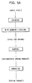
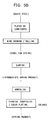
- Figs. 5A and 5B show conventional coloring methods in producing springs.
- the conventional methods for coloring spring can be classified roughly into the method A shown in Fig. 5A according to which the coloring is applied before springs are formed and the method B shown in Fig. 5B according to which the coloring is applied after springs are formed.
- the basic steel is first colored. Subsequently, a wire drawing is applied in the case that the basic steel is a steel wire, whereas a rolling is applied in the case that the basic steel is a steel sheet.
- the basic steel which has been colored and drawn/rolled is then shaped into springs using a specified shaping apparatus. Thereby, intermediate products can be obtained. These intermediate products are made into springs through a process of annealing the intermediate products loaded in an annealing furnace at a specified temperature. According to this method, the basic steel is already colored before being formed.
- the basic steel is plated or lubricated, but is not yet colored, before being formed.
- a specified shaping operation is performed in a shaping process.
- intermediate products in the form of springs can be obtained. These intermediate products are annealed and then colored.
- a coloring method either a chemical conversion treatment or color plating treatment is performed.
- the conventional method A there can be specifically used, as a coloring method, a resin coating method of coating the surface of the basic steel with special resin, a baking finish method of baking paint on the surface thereof.
- a chemical conversion treatment for treating the basic steel with chemicals and an electroplating treatment can be used as a coloring method.
- black is in many cases particularly preferably adopted in order to coincide the surface color tone with the black base color tone or to meet a demand in design.
- Both the electroplating treatment and the chemical conversion treatment are applicable to make springs black.
- a black chrome plating treatment, a black nickel plating treatment, a black rhodium plating treatment and the like are used as an electroplating treatment.
- a black chromate method and a black oxide finish method are used as a chemical conversion treatment.
- the steel material for spring is subjected to an exceedingly large abrasion from a variety of shaping machine tools during the shaping process. Accordingly, coats and paints are often scratched or peeled by the large abrasion, if the basic steel is colored according to the conventional method A in which the coloring is performed by coating with resin or painting before the shaping process.
- the springs are heated at a temperature of 250 to 400°C for 2 to 30 minutes in order to improve a spring characteristic (a low temperature annealing treatment).
- a spring characteristic a low temperature annealing treatment
- a shaping apparatus provided with a detector for detecting the size of spring using an electric signal during the shaping process.
- the surface of the steel material In order to employ such a shaping apparatus, the surface of the steel material must be in a conductive state. When the surface of the steel material is covered with a coat or paint layer, it is brought into an insulated state. Thus, the shaping apparatus provided with the detector cannot be used.
- the conventional method B has the problem of increasing the production costs since a cumbersome treatment, e.g., a chemical conversion treatment or color plating treatment, must be performed to color the intermediate products that have passed through the annealing process.
- a cumbersome treatment e.g., a chemical conversion treatment or color plating treatment
- the invention is directed to a steel material for colored spring comprising a basic steel, and a metallic deposit formed on a surface of the basic steel, the metallic deposit having a metal capable of forming an oxide matter that comes to have a desired color tone by heating.
- This steel material is provided with a deposit of such metal on the surface thereof.
- the steel material is shaped to a spring and then annealed or heated to exhibit a desired color tone on the surface. Accordingly, this steel material can eliminate the coloring process which has been required in the conventional spring production way.
- the deposit serves as a buffer between a spring shaping apparatus and the basic steel.
- the formability of spring can be improved.
- the deposit is conductive because of being made of metal. Accordingly, this steel material can assure use of a detector for detecting the size of spring through application of electricity to the spring.
- the metallic deposit is made of a metal including copper, zinc, and chrome.
- the metallic deposit is formed by two layers, one layer being made of a metal including either copper or zinc, and the other layer being made of a metal including chrome.
- the inner layer of the two-layer deposit being made of copper and the outer layer being made of zinc/chrome alloy, or alternatively the inner layer being made of zinc and the outer layer being made of copper/chrome alloy.
- the steel material formed with the deposit including copper, zinc, and chrome
- copper and zinc diffuse in the deposit to thereby exhibit a so-called gold color tone.
- the chrome is oxidized to form a chromium oxide.
- the chromium oxide e.g., Cr2O3, exhibits a dark gray color tone. Accordingly, the combination of the gold color tone of copper and zinc and the dark gray color tone of chromium oxide make the deposit as a whole exhibit a beautiful black tone.
- the deposit including copper, zinc, and chrome
- these metals diffuse one another in the deposit and the chromium oxide is formed during an annealing process.
- the deposit exhibit a beautiful black tone, thereby making the obtained spring look beautiful.
- the chromium oxide which is formed as a result of heating, prevents rusting of the spring effectively.
- the deposit formed by two layers, the inner layer of copper or zinc and the outer layer of zinc/chrome or copper/chrome alloy can exhibit more beautiful black tone. This is because: 1) chrome of the zinc/chrome or copper/chrome arranged on the outer layer is more easily oxidized to form chromium oxide; and 2) the arrangement of the dark gray color tone on the outer layer and the gold color tone on the inner layer exhibits more beautiful black color tone.
- the deposit has 0.2 to 80.0 weight percent of copper, 0.2 to 10.0 weight percent of chrome.
- the metallic deposit has a thickness of 0.1 to 15 ⁇ m.
- the present invention is further directed to a method for producing a colored spring which comprises the steps of forming the above-mentioned metallic deposit on a surface of a basic steel , shaping the basic steel into an intermediate product having a specified spring like form, and annealing the intermediate product at a temperature range of 200 to 500°C to cause the deposit to have a black color tone.
- This method can produce a colored spring having a beautiful black tone on the surface thereof without providing an additional coloring process.
- the present invention is further directed to a colored spring produced by shaping a basic steel provided with the above-mentioned metallic deposit to an intermediate product having a specified springlike form, and annealing the intermediate product at a temperature range of 200 to 500 °C to cause the deposit to have a black color tone.
- This colored spring has a beautiful black color tone on the surface because the metallic deposit contains copper, zinc, and chrome, and is heated within the temperature range of 200 to 500°C.
- the present invention has been worked out by earnest researches of the inventors. It has been found out that the plating causes no change in the spring characteristic of steel material for spring and that a deposit of specific alloy formed on the surface of the steel material starts assuming a black color tone while being annealed at a low temperature.
- the invention is principally realized by forming, on a surface of a basic steel, a deposit of a metal which forms an oxide coat when being heated and exhibits a desired color tone.
- the basic steel is plated.
- This plating treatment can be applied to a basic steel wire for spring, such as hard steel wire, piano wire and stainless steel wire, or a variety of steel plates for spring.
- a deposit metal used for the plating treatment selected is a metal which is capable of exhibiting a specified color tone after being heated.
- the deposit metal exhibits a specified color tone during the annealing treatment which is to be performed later.
- the basic steel applied with such metallic deposit is formed into a wire by drawing or into a plate by rolling.
- This steel material is shaped into a specified spring form using a shaping apparatus in a subsequent shaping process.
- the deposit formed on the surface thereof functions as lubricant so that the steel material can be worked smoothly in the shaping apparatus.
- the satisfactory formability is attainable even without applying any lubricant unlike the conventional method B.
- An intermediate product obtained after the shaping process is heated at a specified temperature to anneal during a subsequent annealing process, and finally produce a spring.
- the metallic deposit on the surface of the intermediate product produces a specified color tone under heat during the annealing process.
- colored springs are produced in the same producing way as non-colored spring production, that is, without additional processes. Accordingly, colored springs can be produced efficiently and at reduced costs.
- the producing of springs using this steel material eliminates the problem residing in the conventional method A that the paint coat formed on the surface of the basic steel in the coloring process is liable to peel off during the subsequent shaping process. This allows the surface of the finished spring to be beautiful and smooth.
- this steel material obviates the treatment of coloring the spring, which is necessary for the conventional method B, after the intermediate product is annealed, thereby reducing the production costs.
- the metallic deposit is made of two-layers: the inner layer being made of copper and the outer layer being made of zinc/chrome alloy, or alternatively the inner layer being made of zinc and the outer layer being made of copper/chrome alloy.
- the present invention is not limited to the above-mentioned two-layer deposit. It may be appreciated to form a single layer deposit including at least the three elements, copper, zinc, and chrome. Also, it may be appreciated to form a two-layer deposit whose one layer is made of copper/chrome or zinc /chrome, and whose other layer is made of zinc /chrome or copper chrome.
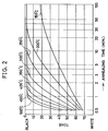
- Fig. 2 is a semilogarithmic graph showing the relationship between annealing temperature (°C), annealing time (min.) and color tone formed in a low temperature annealing treatment.
- This graph was made as follows: First, a hard steel wire was formed with a two-layer deposit, the inner layer being made of copper and the outer layer being made of zinc/chrome alloy. The hard steel wire was drawn at a reduction ratio greater than 50 percent and then annealed. The deposit had 65 weight percent of copper, 5 weight percent of chrome, and 30 weight percent of zinc. The drawn hard steel wire had a final deposit thickness of 0.5 ⁇ m. A number of test pieces were prepared. The annealing temperature and time were changed for each test piece. The color tone of each test piece was measured by a digital colormeter "TC-3600" which is a product of Tokyo Denshoku Kabushiki Kaisha, a Japanese company.
- change in the color tone is closely related to the annealing temperature and the annealing time. It will be seen that a desired change to black color tone occurred in a range of the annealing temperature from 200 to 500 °C for a short annealing time, that is, 1.0 to 30 minutes. At an annealing temperature of not higher than 200 °C , however, the surface of the test piece did not change its color tone greatly, even if being annealed for a substantially long time. Further, the black color tone was not attained even if being annealed for a much longer time.
- an annealing temperature of not lower than 500°C deteriorated the strength of the spring and therefore it is not practical to anneal at such a high temperature. Based on the above test result, accordingly, it will be apparent that setting the annealing temperature within the range of 200 to 500°C is practical or preferable.
- Fig. 3 is a logarithmic graph showing a range where a black color tone is obtainable based on the relationship between copper amount (weight percent) and chrome amount (weight percent) in a deposit. This graph also shows a range of proportions of copper and chrome at which a black color tone produced in the annealing treatment. A horizontal axis of this graph represents the chrome amount (weight percent) and a vertical axis represents the copper amount (weight percent).
- This graph was made as follows: A number of basic steel wires were formed with deposits having different proportion of zinc, copper, and chrome. The plated steel wire was drawn at a reduction ratio greater than 50 percent so that the final thickness of the deposit is 0.5 ⁇ m. The drawn steel wire was shaped into a spring and then annealed at a temperature of 350°C for 10 minutes.
- the deposit produced a gray color tone when the chrome amount was smaller than 0.2 weight percent. Also, no uniform deposit could be formed when the chrome amount was 10 weight percent or greater.
- the deposit produced a gray-green color tone when the copper amount was smaller than 0.2 weight percent. Also, a red-black color tone was produced when the copper amount was 80 weight percent or greater. In both color tones, the spring does not look beautiful.
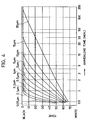
- Fig. 4 is a semilogarithmic graph showing the relationship between deposit thickness ( ⁇ m), annealing time (min.) and color tone formed in a low temperature annealing treatment.
- This graph was made as follows: First, a number of basic steel wires were plated to have two layers, the inner layer being made of copper, the outer layer being made of zinc/chrome alloy. The proportions of the copper, chrome, and zinc of the deposit were respectively 65, 5, and 30 weight percent. The steel wire was drawn so that the deposit thickness became 0.05 to 20 ⁇ m. The steel wire was shaped into a spring which was then annealed at 400°C. This graph shows a result obtained by checking the color tone of the springs. A horizontal axis of this graph represents the annealing time and a vertical axis thereof represents the color tone.
- the time required for the deposit to become black increases exponentially as the deposit thickness increases. For example, it took 30 minutes for the 15 ⁇ m-deposit to become black, but it took 180 minutes for the 20 ⁇ m-deposit.
- the deposit thickness which assures the black color tone change at the practically highest annealing temperature of 400 °C for the practically longest annealing time of 30 minutes is 15 ⁇ m.
- the graph of Fig. 4 shows the fact that the deposits having a thickness smaller than 15 ⁇ m exhibited the black color tone for shorter than 30 minutes.
- the tone of black color can be desirably changed by controlling the annealing time and the deposit thickness suitably. Also, it is disadvantageous to form a deposit having a thickness greater than 15 ⁇ m because it leads to an increase in the production costs.
- a deposit having a thickness of 0.1 to 15 ⁇ m Accordingly, it will be preferable to form a deposit having a thickness of 0.1 to 15 ⁇ m.
- a basic steel wire employed was a hard steel wire whose carbon content is 0.82 weight percent and whose diameter is 1.80 mm. This basic steel wire was lead-patented and washed with acid to remove scale therefrom. The electroplating treatment was applied to the descaled basic steel wire to form a two layer deposit; the inner layer being made of copper and the outer layer being made of zinc/chrome alloy.
- a plating solution whose composition was: CuSO4 ⁇ 5H2O:240g/1, H2SO4:50g/l, was used at 30°C.
- a copper plate was used as an anode and a current density was set at 5 A/dm2.
- a plating solution whose composition was ZnSO4 ⁇ 7H2O:110g/l, Cr2(SO4)3 ⁇ 3H2O:1 to 50g/l, Na2SO4 ⁇ 10H2O:50g/l, was used at 50°C and was prepared so that the pH thereof was 4.
- a zinc plate was used as an an ode and a current density was set at 5 to 30 A/dm2.
- the precipitation of chrome is adjusted by changing the trivalent Cr-ion concentration in the plating solution and the current density, and the basic wire was formed with the deposit of copper on the inner layer and zinc/chrome alloy on the outer layer which has 5 weight percent of copper, 5 weight percent of chrome, and 90 weight percent of zinc.
- the thickness of the deposit was set at 0.5 ⁇ m after the wire drawing.
- the wire was drawn continuously eight times at a drawing ratio of 88.9 percent in the cross sectional area so that its diameter became 0.60 mm. In this way, there was obtained a steel wire (steel material for spring) whose strength level was equivalent to a C-type hard steel wire specified in JISG3521.
- These steel wires were shaped into a helical spring (intermediate products) whose outside diameter was 10 mm, whose length was 20 mm, and whose number of winding was 20. Thereafter, these springs were annealed at 300°C for 10 minutes and the color tones thereof were compared after being cooled.
- (A), (B), (C), (D) denote color tone before heating, color tone after the heating, number of rotary bending, and state of surface respectively.
- a stainless steel spring wire was employed as basic steel wire.
- the stainless steel spring wire was bright-annealed at 1150°C, and had a diameter of 2.5 mm.
- the electroplating treatment was applied to the basic wire to form a two layer deposit, similarly to Present Example 1. including the inner layer being made of zinc and the outer layer being made of copper/chrome alloy. Also, the deposit had 30 weight percent of zinc, 5 weight percent of chrome.
- plated wire was drawn into a steel wire whose diameter was 1.0 mm and whose deposit thickness was 0.5 ⁇ m.
- the plating conditions were as follows.
- a plating solution whose composition was: ZnSO4 ⁇ 7H2O:110g/1, H2SO4:50g/1, was used at 30°C.
- a zinc plate was used as an anode and a current density was set at 5 A/dm2.
- a plating solution whose composition was: CuSO4 ⁇ 5H2O:240g/1, Cr2(SO4)3 ⁇ 3H2O:1 to 50g/1, Na2SO4 ⁇ 10H2O:50g/1, was used at 50°C and was prepared so that the pH thereof was 4.
- a copper plate was used as an anode and a current density was set at 5 to 30 A/dm2.
- the precipitation of chrome is adjusted by changing the trivalent Cr-ion concentration in the plating solution and the current density.
- the steel wire has a strength equivalent of a stainless steel spring wire WPB specified in JISG4314. Similar to Present Example 1, this steel wire was shaped into a helical spring and then annealed at 350°C for 10 minutes.
- Comparative Example 2 was prepared by shaping the same stainless steel wire into a helical spring in the same manner as Present Example 2. However, the plating treatment was not applied.
- (A), (B), (C), (D) denote color tone before heating, color tone after the heating, number of rotary bending, and state of surface respectively.
Landscapes
- Engineering & Computer Science (AREA)
- Chemical & Material Sciences (AREA)
- Mechanical Engineering (AREA)
- General Engineering & Computer Science (AREA)
- Organic Chemistry (AREA)
- Metallurgy (AREA)
- Materials Engineering (AREA)
- Chemical Kinetics & Catalysis (AREA)
- Wire Processing (AREA)
- Electroplating Methods And Accessories (AREA)
- Springs (AREA)
- Other Surface Treatments For Metallic Materials (AREA)
- Coating With Molten Metal (AREA)
Abstract
Description
- This invention relates to a steel material for colored spring, method for producing a colored spring, and colored spring.
- Springs such as helical springs and plate springs are indispensable parts in assembling a variety of machines. Steel materials for spring are divided roughly into steel wires and steel plates. The steel wires are classified further into hard steel wires, piano wires and stainless steel wires specified in JIS or Japanese Industrial Standard. These basic steels have very similar surface color tone. Particularly, the hard steel wires and the piano wires are indistinguishable only based on the surface color tone.
- The stainless steel wires have generally excellent gloss compared to the hard steel wires or the piano wires, and therefore it is not difficult to distinguish the hard steel wires or the piano wires from the stainless steel wires. However, in the case that a so-called oil drawing or wet drawing, in which the wire is drawn by applying a tensile force while applying oil to the surface of the wire, is performed to the hard steel wires or the piano wires, these wires exhibit increased gloss. As a result, the hard steel wires or the piano wires become indistinguishable from the stainless steel wires.
- The fact that the type of spring is indistinguishable based on the surface color tone as described above will cause the problem that springs which are different in type but similar in shape would be used inadvertently together in the manufacturing process of various machines. Accordingly, the springs are colored to avoid this problem.
- Figs. 5A and 5B show conventional coloring methods in producing springs. As shown in these figures, the conventional methods for coloring spring can be classified roughly into the method A shown in Fig. 5A according to which the coloring is applied before springs are formed and the method B shown in Fig. 5B according to which the coloring is applied after springs are formed.
- More specifically, according to the conventional method A, the basic steel is first colored. Subsequently, a wire drawing is applied in the case that the basic steel is a steel wire, whereas a rolling is applied in the case that the basic steel is a steel sheet. The basic steel which has been colored and drawn/rolled is then shaped into springs using a specified shaping apparatus. Thereby, intermediate products can be obtained. These intermediate products are made into springs through a process of annealing the intermediate products loaded in an annealing furnace at a specified temperature. According to this method, the basic steel is already colored before being formed.
- According to the conventional method B, the basic steel is plated or lubricated, but is not yet colored, before being formed. Then, similar to the conventional method A, after a drawing or rolling is performed, a specified shaping operation is performed in a shaping process. In this way, intermediate products in the form of springs can be obtained. These intermediate products are annealed and then colored. As a coloring method, either a chemical conversion treatment or color plating treatment is performed.
- In the conventional method A, there can be specifically used, as a coloring method, a resin coating method of coating the surface of the basic steel with special resin, a baking finish method of baking paint on the surface thereof. In the conventional method B, a chemical conversion treatment for treating the basic steel with chemicals and an electroplating treatment can be used as a coloring method.
- Incidentally, as a color tone of the final spring, black is in many cases particularly preferably adopted in order to coincide the surface color tone with the black base color tone or to meet a demand in design. Both the electroplating treatment and the chemical conversion treatment are applicable to make springs black. Specifically, a black chrome plating treatment, a black nickel plating treatment, a black rhodium plating treatment and the like are used as an electroplating treatment. A black chromate method and a black oxide finish method are used as a chemical conversion treatment.
- However, the steel material for spring is subjected to an exceedingly large abrasion from a variety of shaping machine tools during the shaping process. Accordingly, coats and paints are often scratched or peeled by the large abrasion, if the basic steel is colored according to the conventional method A in which the coloring is performed by coating with resin or painting before the shaping process.
- Normally, the springs are heated at a temperature of 250 to 400°C for 2 to 30 minutes in order to improve a spring characteristic (a low temperature annealing treatment). Thus, even if the scratches made by the abrasion are of a slight degree, the coats or paints fuse during this heating treatment, causing the springs to stick to each other. As a result, recesses are undesirably formed on the outer circumferential surfaces of the springs through the softening and fusing of the coats.
- Further, there is sometimes employed a shaping apparatus provided with a detector for detecting the size of spring using an electric signal during the shaping process. In order to employ such a shaping apparatus, the surface of the steel material must be in a conductive state. When the surface of the steel material is covered with a coat or paint layer, it is brought into an insulated state. Thus, the shaping apparatus provided with the detector cannot be used.
- For the aforementioned reasons, it has been problematic to color the surface of the basic steel using the conventional method A. On the other hand, the conventional method B has the problem of increasing the production costs since a cumbersome treatment, e.g., a chemical conversion treatment or color plating treatment, must be performed to color the intermediate products that have passed through the annealing process.
- It is an object of the present invention to provide a new steel material which can assure production of colored springs without causing the problems of the prior art.
- It is another object of the present invention to provide a steel material which can as sure production of colored springs having a beautiful black color tone without providing a coloring process either before a shaping process or after an annealing process but only by carrying out a conventional and normal way of spring production.
- It is another object of the present invention to provide a new colored spring which has a beautiful black color tone and does not need high production costs.
- It is another object of the present invention to provide a new colored spring production method which can produce colored springs at reduced costs.
- Accordingly, the invention is directed to a steel material for colored spring comprising a basic steel, and a metallic deposit formed on a surface of the basic steel, the metallic deposit having a metal capable of forming an oxide matter that comes to have a desired color tone by heating.
- This steel material is provided with a deposit of such metal on the surface thereof. The steel material is shaped to a spring and then annealed or heated to exhibit a desired color tone on the surface. Accordingly, this steel material can eliminate the coloring process which has been required in the conventional spring production way.
- Also, the deposit serves as a buffer between a spring shaping apparatus and the basic steel. The formability of spring can be improved. Further, the deposit is conductive because of being made of metal. Accordingly, this steel material can assure use of a detector for detecting the size of spring through application of electricity to the spring.
- Also, it may be appreciated that the metallic deposit is made of a metal including copper, zinc, and chrome.
- Further, it may be preferable that the metallic deposit is formed by two layers, one layer being made of a metal including either copper or zinc, and the other layer being made of a metal including chrome.
- Further, it may be preferable that the inner layer of the two-layer deposit being made of copper and the outer layer being made of zinc/chrome alloy, or alternatively the inner layer being made of zinc and the outer layer being made of copper/chrome alloy.
- With the steel material formed with the deposit including copper, zinc, and chrome, when being heated, copper and zinc diffuse in the deposit to thereby exhibit a so-called gold color tone. On the other hand, the chrome is oxidized to form a chromium oxide. The chromium oxide, e.g., Cr₂O₃, exhibits a dark gray color tone. Accordingly, the combination of the gold color tone of copper and zinc and the dark gray color tone of chromium oxide make the deposit as a whole exhibit a beautiful black tone.
- Specifically, in the deposit including copper, zinc, and chrome, these metals diffuse one another in the deposit and the chromium oxide is formed during an annealing process. As a result, the deposit exhibit a beautiful black tone, thereby making the obtained spring look beautiful.
- Further, the chromium oxide, which is formed as a result of heating, prevents rusting of the spring effectively.
- Further, the deposit formed by two layers, the inner layer of copper or zinc and the outer layer of zinc/chrome or copper/chrome alloy, can exhibit more beautiful black tone. This is because: 1) chrome of the zinc/chrome or copper/chrome arranged on the outer layer is more easily oxidized to form chromium oxide; and 2) the arrangement of the dark gray color tone on the outer layer and the gold color tone on the inner layer exhibits more beautiful black color tone.
- It may be preferable that the deposit has 0.2 to 80.0 weight percent of copper, 0.2 to 10.0 weight percent of chrome. The deposit satisfying the above ranges, when being heated during the annealing, provides more black color tone, thereby making the springs look beautiful.
- Also, it may be preferable that the metallic deposit has a thickness of 0.1 to 15 µm.
- Furthermore, the present invention is further directed to a method for producing a colored spring which comprises the steps of forming the above-mentioned metallic deposit on a surface of a basic steel , shaping the basic steel into an intermediate product having a specified spring like form, and annealing the intermediate product at a temperature range of 200 to 500°C to cause the deposit to have a black color tone.
- This method can produce a colored spring having a beautiful black tone on the surface thereof without providing an additional coloring process.
- Moreover, the present invention is further directed to a colored spring produced by shaping a basic steel provided with the above-mentioned metallic deposit to an intermediate product having a specified springlike form, and annealing the intermediate product at a temperature range of 200 to 500 °C to cause the deposit to have a black color tone.
- This colored spring has a beautiful black color tone on the surface because the metallic deposit contains copper, zinc, and chrome, and is heated within the temperature range of 200 to 500°C.
- The above and other objects, features and advantages of the present invention will become more apparent upon a reading of the following detailed description and drawings.
- Fig. 1 is a flow chart showing an exemplary spring producing method according to the invention;
- Fig. 2 is a semilogarithmic graph showing the relationship between annealing temperature (°C), annealing time (min.), and color tone in a low temperature annealing;
- Fig. 3 is a logarithmic graph showing a region where a black color tone is obtainable based on the relationship between copper amount (weight percent) and chrome amount (weight percent) in a formed deposit;
- Fig. 4 is a semilogarithmic graph showing the relationship between deposit thickness (µm), annealing time (min.), and color tone; and
- Figs. 5A and 5B are flow charts showing conventional spring producing methods A and B respectively.
- The present invention has been worked out by earnest researches of the inventors. It has been found out that the plating causes no change in the spring characteristic of steel material for spring and that a deposit of specific alloy formed on the surface of the steel material starts assuming a black color tone while being annealed at a low temperature. The invention is principally realized by forming, on a surface of a basic steel, a deposit of a metal which forms an oxide coat when being heated and exhibits a desired color tone.
- An exemplary spring producing method according to the invention will be described with reference to Fig. 1. First, the basic steel is plated. This plating treatment can be applied to a basic steel wire for spring, such as hard steel wire, piano wire and stainless steel wire, or a variety of steel plates for spring. As a deposit metal used for the plating treatment selected is a metal which is capable of exhibiting a specified color tone after being heated.
- The deposit metal exhibits a specified color tone during the annealing treatment which is to be performed later. The basic steel applied with such metallic deposit is formed into a wire by drawing or into a plate by rolling. This steel material is shaped into a specified spring form using a shaping apparatus in a subsequent shaping process. In this case, although the steel material is subjected to an exceedingly large abrasion during the shaping process, the deposit formed on the surface thereof functions as lubricant so that the steel material can be worked smoothly in the shaping apparatus. Thus, the satisfactory formability is attainable even without applying any lubricant unlike the conventional method B.
- An intermediate product obtained after the shaping process is heated at a specified temperature to anneal during a subsequent annealing process, and finally produce a spring. The metallic deposit on the surface of the intermediate product produces a specified color tone under heat during the annealing process.
- In this way, colored springs are produced in the same producing way as non-colored spring production, that is, without additional processes. Accordingly, colored springs can be produced efficiently and at reduced costs.
- Further, the producing of springs using this steel material eliminates the problem residing in the conventional method A that the paint coat formed on the surface of the basic steel in the coloring process is liable to peel off during the subsequent shaping process. This allows the surface of the finished spring to be beautiful and smooth.
- Further, the use of this steel material obviates the treatment of coloring the spring, which is necessary for the conventional method B, after the intermediate product is annealed, thereby reducing the production costs.
- In this embodiment, the metallic deposit is made of two-layers: the inner layer being made of copper and the outer layer being made of zinc/chrome alloy, or alternatively the inner layer being made of zinc and the outer layer being made of copper/chrome alloy.
- However, it should be noted that the present invention is not limited to the above-mentioned two-layer deposit. It may be appreciated to form a single layer deposit including at least the three elements, copper, zinc, and chrome. Also, it may be appreciated to form a two-layer deposit whose one layer is made of copper/chrome or zinc /chrome, and whose other layer is made of zinc /chrome or copper chrome.
- Next, appropriate or preferable element proportions, thickness, annealing temperature of deposit will be described with reference to Figs. 2 to 4.
- Fig. 2 is a semilogarithmic graph showing the relationship between annealing temperature (°C), annealing time (min.) and color tone formed in a low temperature annealing treatment.
- This graph was made as follows: First, a hard steel wire was formed with a two-layer deposit, the inner layer being made of copper and the outer layer being made of zinc/chrome alloy. The hard steel wire was drawn at a reduction ratio greater than 50 percent and then annealed. The deposit had 65 weight percent of copper, 5 weight percent of chrome, and 30 weight percent of zinc. The drawn hard steel wire had a final deposit thickness of 0.5 µm. A number of test pieces were prepared. The annealing temperature and time were changed for each test piece. The color tone of each test piece was measured by a digital colormeter "TC-3600" which is a product of Tokyo Denshoku Kabushiki Kaisha, a Japanese company.
- As will be seen from this graph, change in the color tone is closely related to the annealing temperature and the annealing time. It will be seen that a desired change to black color tone occurred in a range of the annealing temperature from 200 to 500 °C for a short annealing time, that is, 1.0 to 30 minutes. At an annealing temperature of not higher than 200 °C , however, the surface of the test piece did not change its color tone greatly, even if being annealed for a substantially long time. Further, the black color tone was not attained even if being annealed for a much longer time. Also, an annealing temperature of not lower than 500°C deteriorated the strength of the spring and therefore it is not practical to anneal at such a high temperature. Based on the above test result, accordingly, it will be apparent that setting the annealing temperature within the range of 200 to 500°C is practical or preferable.
- Fig. 3 is a logarithmic graph showing a range where a black color tone is obtainable based on the relationship between copper amount (weight percent) and chrome amount (weight percent) in a deposit. This graph also shows a range of proportions of copper and chrome at which a black color tone produced in the annealing treatment. A horizontal axis of this graph represents the chrome amount (weight percent) and a vertical axis represents the copper amount (weight percent).
- This graph was made as follows: A number of basic steel wires were formed with deposits having different proportion of zinc, copper, and chrome. The plated steel wire was drawn at a reduction ratio greater than 50 percent so that the final thickness of the deposit is 0.5 µm. The drawn steel wire was shaped into a spring and then annealed at a temperature of 350°C for 10 minutes.
- As shown in this graph, the deposit produced a gray color tone when the chrome amount was smaller than 0.2 weight percent. Also, no uniform deposit could be formed when the chrome amount was 10 weight percent or greater.
- The deposit produced a gray-green color tone when the copper amount was smaller than 0.2 weight percent. Also, a red-black color tone was produced when the copper amount was 80 weight percent or greater. In both color tones, the spring does not look beautiful.
- Accordingly, it will be seen that a beautiful black color tone is obtainable when the deposit is within the rectangular range indicated in the graph, that is, the chrome amount being 0.2 to 10 weight percent, the copper amount being 0.2 to 80 weight percent.
- Fig. 4 is a semilogarithmic graph showing the relationship between deposit thickness (µm), annealing time (min.) and color tone formed in a low temperature annealing treatment.
- This graph was made as follows: First, a number of basic steel wires were plated to have two layers, the inner layer being made of copper, the outer layer being made of zinc/chrome alloy. The proportions of the copper, chrome, and zinc of the deposit were respectively 65, 5, and 30 weight percent. The steel wire was drawn so that the deposit thickness became 0.05 to 20 µm. The steel wire was shaped into a spring which was then annealed at 400°C. This graph shows a result obtained by checking the color tone of the springs. A horizontal axis of this graph represents the annealing time and a vertical axis thereof represents the color tone.
- As will be seen from this graph, in the case of the deposit thickness being smaller than 0.1 µm, the desired color tone was not realizable even if the annealing time was changed anyway. However, in the case of the deposit thickness being 0.1 µm or greater, when the annealing was performed for longer than a specified time, the deposit remained uniform and produced a beautiful black color tone.
- Also, it will be seen that the time required for the deposit to become black increases exponentially as the deposit thickness increases. For example, it took 30 minutes for the 15 µm-deposit to become black, but it took 180 minutes for the 20 µm-deposit.
- As will be seen from Fig. 2, the higher the annealing temperature, the more drastically the color tone changes, i.e., the shorter time it takes for the deposit to become black. However, a practical annealing temperature for springs is 250 to 400 °C and springs are seldom annealed at a temperature higher than 400 °C.
- Accordingly, it will be seen from the graphs of Figs. 2 and 4 that the deposit thickness which assures the black color tone change at the practically highest annealing temperature of 400 °C for the practically longest annealing time of 30 minutes is 15 µm. The graph of Fig. 4 shows the fact that the deposits having a thickness smaller than 15 µm exhibited the black color tone for shorter than 30 minutes. The tone of black color can be desirably changed by controlling the annealing time and the deposit thickness suitably. Also, it is disadvantageous to form a deposit having a thickness greater than 15 µm because it leads to an increase in the production costs.
- Accordingly, it will be preferable to form a deposit having a thickness of 0.1 to 15 µm.
- Next, characteristic performances of the present invention will be described by a comparison between a spring (Present Example 1) which is formed with a deposit according to the present invention and a spring (Comparative Example 1) which is not formed with any deposit.
- As a basic steel wire employed was a hard steel wire whose carbon content is 0.82 weight percent and whose diameter is 1.80 mm. This basic steel wire was lead-patented and washed with acid to remove scale therefrom. The electroplating treatment was applied to the descaled basic steel wire to form a two layer deposit; the inner layer being made of copper and the outer layer being made of zinc/chrome alloy.
- For the copper plating treatment, a plating solution whose composition was: CuSO₄·5H₂O:240g/1, H₂SO₄:50g/l, was used at 30°C. A copper plate was used as an anode and a current density was set at 5 A/dm².
- On the other hand, for the zinc/chrome plating treatment, a plating solution whose composition was ZnSO₄·7H₂O:110g/l, Cr₂(SO₄)₃·3H₂O:1 to 50g/l, Na₂SO₄·10H₂O:50g/l, was used at 50°C and was prepared so that the pH thereof was 4. A zinc plate was used as an an ode and a current density was set at 5 to 30 A/dm².
- The precipitation of chrome is adjusted by changing the trivalent Cr-ion concentration in the plating solution and the current density, and the basic wire was formed with the deposit of copper on the inner layer and zinc/chrome alloy on the outer layer which has 5 weight percent of copper, 5 weight percent of chrome, and 90 weight percent of zinc. The thickness of the deposit was set at 0.5 µm after the wire drawing.
- After the formation of the two layer deposit, the wire was drawn continuously eight times at a drawing ratio of 88.9 percent in the cross sectional area so that its diameter became 0.60 mm. In this way, there was obtained a steel wire (steel material for spring) whose strength level was equivalent to a C-type hard steel wire specified in JISG3521.
- As Comparative Example 1, a steel wire having a diameter of 0.60 mm was obtained by drawing the basic wire having a diameter of 1.80 mm similarly to the case of Present Example 1 without forming any deposit.
- These steel wires were shaped into a helical spring (intermediate products) whose outside diameter was 10 mm, whose length was 20 mm, and whose number of winding was 20. Thereafter, these springs were annealed at 300°C for 10 minutes and the color tones thereof were compared after being cooled.
- To measure the mechanical characteristics of each of Present and Comparative Examples, further, there were prepared another steel wire which was kept straight, that is, not shaped into a spring, and was annealed similarly. These straight steel wires were measured for the tensile strength, torsional characteristic and fatigue strength. The fatigue strength was measured in accordance with Nakamura Rotary Bending Test.
- TABLE-1 below shows preconditions and test results.
TABLE-1 PRECONDITIONS WIRE DIAM. (mm) DEPOSIT THICKNESS (µm) COMPOSITION OF PLATING SOLUTION ANNEALING CONDITION Cu (wt%) Zn (wt%) Cr (wt%) TEMP (°C) TIME (min) Present Example 1 0.60 0.5 5.0 90.0 5.0 300 10 Comparative Example 1 0.60 - - - - 300 10 TEST RESULTS COLOR TONE TENSILE STRENGTH (N/mm² ) TORSIONAL CHARA. FATIGUE STRENGTH (N/mm²) (A) (B) (C) (D) Present Example 1 WHITE BLACK 2,250 27 GOOD 620 Comparative Example 1 WHITE WHITE 2,260 27 GOOD 622 - (A), (B), (C), (D) denote color tone before heating, color tone after the heating, number of rotary bending, and state of surface respectively.
- As seen from TABLE-1, the surface of Present Example 1, which was originally white, changed into a beautiful black color tone which is distinguishable color tone. Contrary to this, the color tone of the spring of Comparative Example 1 remained white which is normal or undistinguishable color tone.
- No big difference was found between these springs in terms of the tensile strength, torsional characteristic and fatigue strength. The comparison made in these springs' easiness for coiling showed that the spring according to the invention has a better formability because the plating treatment was applied thereto. Thus, the forming operation could be performed stably, which led to a smaller variation in pitches and a better easiness for coiling.
- Further, another comparison was made. In this comparison, in Present Example 2, a stainless steel spring wire was employed as basic steel wire. The stainless steel spring wire was bright-annealed at 1150°C, and had a diameter of 2.5 mm. The electroplating treatment was applied to the basic wire to form a two layer deposit, similarly to Present Example 1. including the inner layer being made of zinc and the outer layer being made of copper/chrome alloy. Also, the deposit had 30 weight percent of zinc, 5 weight percent of chrome. Thus plated wire was drawn into a steel wire whose diameter was 1.0 mm and whose deposit thickness was 0.5 µm.
- The plating conditions were as follows. For the zinc plating treatment, a plating solution whose composition was: ZnSO₄·7H₂O:110g/1, H₂SO₄:50g/1,
was used at 30°C. A zinc plate was used as an anode and a current density was set at 5 A/dm². - On the other hand, for the copper/chrome plating treatment, a plating solution whose composition was:
CuSO₄·5H₂O:240g/1, Cr₂(SO₄)₃·3H₂O:1 to 50g/1, Na₂SO₄·10H₂O:50g/1, was used at 50°C and was prepared so that the pH thereof was 4. A copper plate was used as an anode and a current density was set at 5 to 30 A/dm². The precipitation of chrome is adjusted by changing the trivalent Cr-ion concentration in the plating solution and the current density. - The steel wire has a strength equivalent of a stainless steel spring wire WPB specified in JISG4314. Similar to Present Example 1, this steel wire was shaped into a helical spring and then annealed at 350°C for 10 minutes.
- Comparative Example 2 was prepared by shaping the same stainless steel wire into a helical spring in the same manner as Present Example 2. However, the plating treatment was not applied.
- Similar comparison tests were conducted. TABLE-2 below shows preconditions and test results.
TABLE-2 PRECONDITIONS WIRE DIAM. (mm) DEPOSIT THICKNESS (µm) COMPOSITION OF PLATING SOLUTION ANNEALING CONDITION Cu (wt%) Zn (wt%) Cr (wt%) TEMP (°C) TIME (min) Present Example 2 1.00 0.5 65.0 30.0 5.0 350 10 Comparative Example 2 1.00 - - - - 350 10 TEST RESULTS COLOR TONE TENSILE STRENGTH (N/mm² ) TORSIONAL CHARA. FATIGUE STRENGTH (N/mm² ) (A) (B) (C) (D) Present Example 2 WHITE BLACK 1,970 10 GOOD 300 Comparative Example 2 WHITE WHITE 1,980 9 GOOD 310 - (A), (B), (C), (D) denote color tone before heating, color tone after the heating, number of rotary bending, and state of surface respectively.
- As seen from TABLE-2, similar to the preceding comparison, the surface of Present Example 2, which was originally white, changed into a beautiful black color tone which was clearly distinguishable from normal springs. Contrary to this, the color tone of Comparative Example 2 remained white and thus it was impossible to distinguish this spring from non-colored springs.
- No big difference was found between these springs in terms of the tensile strength, torsional characteristic and fatigue strength.
- Although the present invention has been fully described by way of example with reference to the accompanying drawings, it is to be understood that various changes and modifications will be apparent to those skilled in the art. Therefore, unless otherwise stated changes and modifications of the invention should be construed as being included therein.
Claims (10)
- A steel material for colored spring comprising:
a basic steel ; and
a metallic deposit formed on a surface of the basic steel, the metallic deposit having a metal capable of forming an oxide matter that comes to have a desired color tone by heating. - A steel material as defined in claim 1 wherein the metallic deposit is made of a metal including copper, zinc, and chrome.
- A steel material as defined in claim 2 wherein the metallic deposit is formed by two layers, one layer being made of a metal including either of zinc or copper, and the other layer being made of a metal including chrome.
- A steel material as defined in claim 3 wherein the inner layer of the two-layer deposit is made of copper, and the outer layer is made of zinc/chrome alloy.
- A steel material as defined in claim 3 wherein the inner layer of the two-layer deposit is made of zinc, and the outer layer is made of copper/chrome alloy.
- A steel material as defined in claim 2 wherein the metallic deposit has 0.2 to 80.0 weight percent of copper, 0.2 to 10.0 weight percent of chrome.
- A steel material as defined in claim 2 wherein the metallic deposit has a thickness of 0.1 to 15 µm.
- A method for producing a colored spring comprising:
forming on a surface of a basic steel a metallic deposit including copper, zinc, and chrome;
shaping the basic steel formed with the metallic deposit to an intermediate product having a specified springlike form; and
annealing the intermediate product at a temperature range of 200 to 500°C so that the metallic deposit will produce a black color tone. - A producing method as defined in claim 8 further comprising a step of drawing the basic steel formed with the metallic deposit so that the metallic deposit has a thickness of 0.1 to 15 µm.
- A colored spring produced by:
forming on a surface of a basic steel a metallic deposit including copper, zinc, and chrome;
shaping the basic steel formed with the metallic deposit to an intermediate product having a specified springlike form; and
annealing the intermediate product at a temperature range of 200 to 500°C so that the metallic deposit will produce a black color tone.
Applications Claiming Priority (4)
| Application Number | Priority Date | Filing Date | Title |
|---|---|---|---|
| JP90112/93 | 1993-04-16 | ||
| JP9011293 | 1993-04-16 | ||
| JP298609/93 | 1993-11-29 | ||
| JP5298609A JP3017910B2 (en) | 1993-04-16 | 1993-11-29 | Method of manufacturing spring products |
Publications (3)
| Publication Number | Publication Date |
|---|---|
| EP0620292A2 true EP0620292A2 (en) | 1994-10-19 |
| EP0620292A3 EP0620292A3 (en) | 1994-10-26 |
| EP0620292B1 EP0620292B1 (en) | 1997-09-17 |
Family
ID=26431618
Family Applications (1)
| Application Number | Title | Priority Date | Filing Date |
|---|---|---|---|
| EP94105799A Expired - Lifetime EP0620292B1 (en) | 1993-04-16 | 1994-04-14 | Steel material for colored spring, method for producing colored spring, and colored spring |
Country Status (8)
| Country | Link |
|---|---|
| US (1) | US5455121A (en) |
| EP (1) | EP0620292B1 (en) |
| JP (1) | JP3017910B2 (en) |
| KR (1) | KR0119721B1 (en) |
| AU (1) | AU669267B2 (en) |
| CA (1) | CA2121392C (en) |
| DE (1) | DE69405627T2 (en) |
| ES (1) | ES2108900T3 (en) |
Cited By (1)
| Publication number | Priority date | Publication date | Assignee | Title |
|---|---|---|---|---|
| WO2002068704A1 (en) * | 2001-02-28 | 2002-09-06 | N.V. Bekaert S.A. | Colored wire and method of manufacturing |
Families Citing this family (3)
| Publication number | Priority date | Publication date | Assignee | Title |
|---|---|---|---|---|
| US20060286400A1 (en) * | 2005-06-17 | 2006-12-21 | Jarden Zinc Products, Inc. | Substrate with alloy finish and method of making |
| US20100221574A1 (en) * | 2009-02-27 | 2010-09-02 | Rochester Thomas H | Zinc alloy mechanically deposited coatings and methods of making the same |
| DE112018002665T5 (en) * | 2017-05-25 | 2020-02-27 | Sumitomo Electric Industries, Ltd. | Inclined coil spring and connecting element |
Citations (7)
| Publication number | Priority date | Publication date | Assignee | Title |
|---|---|---|---|---|
| US3634147A (en) * | 1969-11-20 | 1972-01-11 | United States Steel Corp | Corrosion resistant tin-free steel and method for producing same |
| US3778315A (en) * | 1970-06-11 | 1973-12-11 | Cominco Lyf | Coating process |
| GB2076432A (en) * | 1980-03-12 | 1981-12-02 | Irca Spa Ind | Cu-Ni coatings on ferrous substrates |
| JPS57190139A (en) * | 1981-05-15 | 1982-11-22 | Nippon Steel Corp | Coated spring |
| JPS6326383A (en) * | 1986-07-17 | 1988-02-03 | Sawahira:Kk | Coating method for coil spring |
| EP0269006A2 (en) * | 1986-11-21 | 1988-06-01 | Nippon Mining Company Limited | Colored zinc coating |
| EP0551566A1 (en) * | 1991-12-25 | 1993-07-21 | SHINKO KOSEN KOGYO KABUSHIKI KAISHA also known as SHINKO WIRE CO.LTD. | Color-developing plated metal for spring and the method of using the same |
Family Cites Families (7)
| Publication number | Priority date | Publication date | Assignee | Title |
|---|---|---|---|---|
| US2490700A (en) * | 1943-08-24 | 1949-12-06 | John S Nachtman | Production of alloy coating on base metal material |
| US3634137A (en) * | 1968-09-26 | 1972-01-11 | Fuji Photo Film Co Ltd | Magnetic recording medium |
| US3966183A (en) * | 1974-04-26 | 1976-06-29 | David Dweck | Article including an endless coil spring |
| US4036206A (en) * | 1976-07-30 | 1977-07-19 | E. I. Du Pont De Nemours And Company | Selective solar energy absorption |
| JPS63114083A (en) * | 1986-10-30 | 1988-05-18 | 日立電線株式会社 | Lead frame for connector |
| JPH01224540A (en) * | 1988-02-29 | 1989-09-07 | Kobe Steel Ltd | Fine spring |
| DE3909694A1 (en) * | 1988-03-30 | 1989-10-12 | Nihon Parkerizing | PRODUCTION OF BLACK COVER ON HARD SURFACES |
-
1993
- 1993-11-29 JP JP5298609A patent/JP3017910B2/en not_active Expired - Fee Related
-
1994
- 1994-03-11 US US08/212,751 patent/US5455121A/en not_active Expired - Fee Related
- 1994-04-02 KR KR1019940007000A patent/KR0119721B1/en not_active IP Right Cessation
- 1994-04-14 ES ES94105799T patent/ES2108900T3/en not_active Expired - Lifetime
- 1994-04-14 EP EP94105799A patent/EP0620292B1/en not_active Expired - Lifetime
- 1994-04-14 AU AU59463/94A patent/AU669267B2/en not_active Ceased
- 1994-04-14 DE DE69405627T patent/DE69405627T2/en not_active Expired - Fee Related
- 1994-04-15 CA CA002121392A patent/CA2121392C/en not_active Expired - Fee Related
Patent Citations (7)
| Publication number | Priority date | Publication date | Assignee | Title |
|---|---|---|---|---|
| US3634147A (en) * | 1969-11-20 | 1972-01-11 | United States Steel Corp | Corrosion resistant tin-free steel and method for producing same |
| US3778315A (en) * | 1970-06-11 | 1973-12-11 | Cominco Lyf | Coating process |
| GB2076432A (en) * | 1980-03-12 | 1981-12-02 | Irca Spa Ind | Cu-Ni coatings on ferrous substrates |
| JPS57190139A (en) * | 1981-05-15 | 1982-11-22 | Nippon Steel Corp | Coated spring |
| JPS6326383A (en) * | 1986-07-17 | 1988-02-03 | Sawahira:Kk | Coating method for coil spring |
| EP0269006A2 (en) * | 1986-11-21 | 1988-06-01 | Nippon Mining Company Limited | Colored zinc coating |
| EP0551566A1 (en) * | 1991-12-25 | 1993-07-21 | SHINKO KOSEN KOGYO KABUSHIKI KAISHA also known as SHINKO WIRE CO.LTD. | Color-developing plated metal for spring and the method of using the same |
Non-Patent Citations (2)
| Title |
|---|
| PATENT ABSTRACTS OF JAPAN vol. 12, no. 237 (C-509) (3084) 6 July 1988 & JP-A-63 026 383 (SAWAHIRA) 3 February 1988 * |
| PATENT ABSTRACTS OF JAPAN vol. 7, no. 41 (M-194) (1186) 18 February 1983 & JP-A-57 190 139 (SHIN NIPPON SEITETSU) 22 November 1982 * |
Cited By (1)
| Publication number | Priority date | Publication date | Assignee | Title |
|---|---|---|---|---|
| WO2002068704A1 (en) * | 2001-02-28 | 2002-09-06 | N.V. Bekaert S.A. | Colored wire and method of manufacturing |
Also Published As
| Publication number | Publication date |
|---|---|
| DE69405627D1 (en) | 1997-10-23 |
| CA2121392A1 (en) | 1994-10-17 |
| JPH06346934A (en) | 1994-12-20 |
| EP0620292B1 (en) | 1997-09-17 |
| KR0119721B1 (en) | 1997-10-22 |
| JP3017910B2 (en) | 2000-03-13 |
| AU5946394A (en) | 1994-10-20 |
| US5455121A (en) | 1995-10-03 |
| EP0620292A3 (en) | 1994-10-26 |
| ES2108900T3 (en) | 1998-01-01 |
| DE69405627T2 (en) | 1998-04-30 |
| AU669267B2 (en) | 1996-05-30 |
| CA2121392C (en) | 2000-10-17 |
Similar Documents
| Publication | Publication Date | Title |
|---|---|---|
| US6040067A (en) | Hard coated copper alloys | |
| JP6611602B2 (en) | Silver plating material and method for producing the same | |
| EP0551566A1 (en) | Color-developing plated metal for spring and the method of using the same | |
| EP0620292A2 (en) | Steel material for colored spring, method for producing colored spring, and colored spring | |
| US5989732A (en) | Stainless steel wire and producing method thereof | |
| JPH052940A (en) | Material for electric contact and manufacture the same | |
| EP0608466B1 (en) | Steel wire for automatic coiling and production process thereof | |
| EP3282033A1 (en) | Zinc-aluminum-alloy-coated shaped steel wire with superior corrosion resistance and method for producing same | |
| CN111317220B (en) | Aluminum alloy button and preparation method thereof | |
| JP7281971B2 (en) | Electrical contact material and its manufacturing method, connector terminal, connector and electronic component | |
| US6205643B1 (en) | Method for manufacturing an electrically conductive metallic strip | |
| JP7281970B2 (en) | Electrical contact material and its manufacturing method, connector terminal, connector and electronic component | |
| KR100614025B1 (en) | Resin coated steel sheet, cartridge cap and cartridge barrel using it | |
| US5238544A (en) | Electro-deposition coated member, process for producing electro-deposition coated member, and electro-deposition coating composition used therefor | |
| JPS6045715B2 (en) | Manufacturing method for energizing conductor roll | |
| JP7353928B2 (en) | Materials for electrical contacts and their manufacturing methods, connector terminals, connectors, and electronic components | |
| KR101106011B1 (en) | A ferritic stainless steel having a corrosion-resisting layer | |
| JP2000282176A (en) | Steel wire for heat resistant spring, and its production | |
| JPH06220688A (en) | Colored spring steel formed article and its production | |
| KR100899010B1 (en) | Manufacturing Method for Material having Color Oxide Layer with High Corrosion-resistance on Ni Plating Layer | |
| JPH0711486A (en) | Colored spring steel formed product and its production | |
| KR101106010B1 (en) | Method for manufacturing ferritic stainless steel having a corrosion-resisting layer | |
| JPH0857923A (en) | Screw having a good corrosion resistance, abrasion resistance and seizure resistance | |
| CN1320721A (en) | Nickel coated high-carbon steel wire for spring and making method thereof | |
| JPS586763B2 (en) | Manufacturing method for plated steel coil springs |
Legal Events
| Date | Code | Title | Description |
|---|---|---|---|
| PUAI | Public reference made under article 153(3) epc to a published international application that has entered the european phase |
Free format text: ORIGINAL CODE: 0009012 |
|
| PUAL | Search report despatched |
Free format text: ORIGINAL CODE: 0009013 |
|
| AK | Designated contracting states |
Kind code of ref document: A2 Designated state(s): BE CH DE ES FR GB IT LI NL |
|
| AK | Designated contracting states |
Kind code of ref document: A3 Designated state(s): BE CH DE ES FR GB IT LI NL |
|
| 17P | Request for examination filed |
Effective date: 19941130 |
|
| 17Q | First examination report despatched |
Effective date: 19960124 |
|
| GRAG | Despatch of communication of intention to grant |
Free format text: ORIGINAL CODE: EPIDOS AGRA |
|
| GRAH | Despatch of communication of intention to grant a patent |
Free format text: ORIGINAL CODE: EPIDOS IGRA |
|
| GRAH | Despatch of communication of intention to grant a patent |
Free format text: ORIGINAL CODE: EPIDOS IGRA |
|
| GRAA | (expected) grant |
Free format text: ORIGINAL CODE: 0009210 |
|
| AK | Designated contracting states |
Kind code of ref document: B1 Designated state(s): BE CH DE ES FR GB IT LI NL |
|
| REG | Reference to a national code |
Ref country code: CH Ref legal event code: EP |
|
| REF | Corresponds to: |
Ref document number: 69405627 Country of ref document: DE Date of ref document: 19971023 |
|
| ITF | It: translation for a ep patent filed |
Owner name: SOCIETA' ITALIANA BREVETTI S.P.A. |
|
| ET | Fr: translation filed | ||
| REG | Reference to a national code |
Ref country code: ES Ref legal event code: FG2A Ref document number: 2108900 Country of ref document: ES Kind code of ref document: T3 |
|
| REG | Reference to a national code |
Ref country code: CH Ref legal event code: NV Representative=s name: PATENTANWAELTE SCHAAD, BALASS, MENZL & PARTNER AG |
|
| PGFP | Annual fee paid to national office [announced via postgrant information from national office to epo] |
Ref country code: FR Payment date: 19980325 Year of fee payment: 5 |
|
| PGFP | Annual fee paid to national office [announced via postgrant information from national office to epo] |
Ref country code: GB Payment date: 19980406 Year of fee payment: 5 |
|
| PGFP | Annual fee paid to national office [announced via postgrant information from national office to epo] |
Ref country code: ES Payment date: 19980414 Year of fee payment: 5 |
|
| PGFP | Annual fee paid to national office [announced via postgrant information from national office to epo] |
Ref country code: BE Payment date: 19980416 Year of fee payment: 5 |
|
| PGFP | Annual fee paid to national office [announced via postgrant information from national office to epo] |
Ref country code: NL Payment date: 19980430 Year of fee payment: 5 |
|
| PGFP | Annual fee paid to national office [announced via postgrant information from national office to epo] |
Ref country code: CH Payment date: 19980501 Year of fee payment: 5 |
|
| PGFP | Annual fee paid to national office [announced via postgrant information from national office to epo] |
Ref country code: DE Payment date: 19980630 Year of fee payment: 5 |
|
| PLBE | No opposition filed within time limit |
Free format text: ORIGINAL CODE: 0009261 |
|
| STAA | Information on the status of an ep patent application or granted ep patent |
Free format text: STATUS: NO OPPOSITION FILED WITHIN TIME LIMIT |
|
| 26N | No opposition filed | ||
| PG25 | Lapsed in a contracting state [announced via postgrant information from national office to epo] |
Ref country code: GB Free format text: LAPSE BECAUSE OF NON-PAYMENT OF DUE FEES Effective date: 19990414 |
|
| PG25 | Lapsed in a contracting state [announced via postgrant information from national office to epo] |
Ref country code: ES Free format text: THE PATENT HAS BEEN ANNULLED BY A DECISION OF A NATIONAL AUTHORITY Effective date: 19990415 |
|
| PG25 | Lapsed in a contracting state [announced via postgrant information from national office to epo] |
Ref country code: LI Free format text: LAPSE BECAUSE OF NON-PAYMENT OF DUE FEES Effective date: 19990430 Ref country code: CH Free format text: LAPSE BECAUSE OF NON-PAYMENT OF DUE FEES Effective date: 19990430 Ref country code: BE Free format text: LAPSE BECAUSE OF NON-PAYMENT OF DUE FEES Effective date: 19990430 |
|
| BERE | Be: lapsed |
Owner name: SHINKO KOSEN KOGYO K.K. Effective date: 19990430 |
|
| PG25 | Lapsed in a contracting state [announced via postgrant information from national office to epo] |
Ref country code: NL Free format text: LAPSE BECAUSE OF NON-PAYMENT OF DUE FEES Effective date: 19991101 |
|
| GBPC | Gb: european patent ceased through non-payment of renewal fee |
Effective date: 19990414 |
|
| REG | Reference to a national code |
Ref country code: CH Ref legal event code: PL |
|
| PG25 | Lapsed in a contracting state [announced via postgrant information from national office to epo] |
Ref country code: FR Free format text: LAPSE BECAUSE OF NON-PAYMENT OF DUE FEES Effective date: 19991231 |
|
| NLV4 | Nl: lapsed or anulled due to non-payment of the annual fee |
Effective date: 19991101 |
|
| REG | Reference to a national code |
Ref country code: FR Ref legal event code: ST |
|
| PG25 | Lapsed in a contracting state [announced via postgrant information from national office to epo] |
Ref country code: DE Free format text: LAPSE BECAUSE OF NON-PAYMENT OF DUE FEES Effective date: 20000201 |
|
| REG | Reference to a national code |
Ref country code: ES Ref legal event code: FD2A Effective date: 20010604 |
|
| PG25 | Lapsed in a contracting state [announced via postgrant information from national office to epo] |
Ref country code: IT Free format text: LAPSE BECAUSE OF NON-PAYMENT OF DUE FEES Effective date: 20050414 |