EP0620192A1 - Solid-liquid separator for sludge - Google Patents
Solid-liquid separator for sludge Download PDFInfo
- Publication number
- EP0620192A1 EP0620192A1 EP93119324A EP93119324A EP0620192A1 EP 0620192 A1 EP0620192 A1 EP 0620192A1 EP 93119324 A EP93119324 A EP 93119324A EP 93119324 A EP93119324 A EP 93119324A EP 0620192 A1 EP0620192 A1 EP 0620192A1
- Authority
- EP
- European Patent Office
- Prior art keywords
- sludge
- tank
- coagulant
- container
- intake
- Prior art date
- Legal status (The legal status is an assumption and is not a legal conclusion. Google has not performed a legal analysis and makes no representation as to the accuracy of the status listed.)
- Ceased
Links
Images


Classifications
-
- C—CHEMISTRY; METALLURGY
- C02—TREATMENT OF WATER, WASTE WATER, SEWAGE, OR SLUDGE
- C02F—TREATMENT OF WATER, WASTE WATER, SEWAGE, OR SLUDGE
- C02F11/00—Treatment of sludge; Devices therefor
- C02F11/12—Treatment of sludge; Devices therefor by de-watering, drying or thickening
- C02F11/14—Treatment of sludge; Devices therefor by de-watering, drying or thickening with addition of chemical agents
-
- C—CHEMISTRY; METALLURGY
- C02—TREATMENT OF WATER, WASTE WATER, SEWAGE, OR SLUDGE
- C02F—TREATMENT OF WATER, WASTE WATER, SEWAGE, OR SLUDGE
- C02F1/00—Treatment of water, waste water, or sewage
- C02F1/52—Treatment of water, waste water, or sewage by flocculation or precipitation of suspended impurities
- C02F1/5281—Installations for water purification using chemical agents
Landscapes
- Chemical & Material Sciences (AREA)
- Chemical Kinetics & Catalysis (AREA)
- General Chemical & Material Sciences (AREA)
- Life Sciences & Earth Sciences (AREA)
- Hydrology & Water Resources (AREA)
- Engineering & Computer Science (AREA)
- Environmental & Geological Engineering (AREA)
- Water Supply & Treatment (AREA)
- Organic Chemistry (AREA)
- Treatment Of Sludge (AREA)
- Separation Of Suspended Particles By Flocculating Agents (AREA)
Abstract
A solid-liquid separator for sludge which includes a tank (1) with a sludge suction port (2), an intake/exhaust port (3) and a sludge discharge port (4). A plurality of agitating blades (6) are mounted on a rotatable shaft (7) within the tank and are capable of being driven in either of two rotational directions. A plurality of injection nozzles (5) are internally mounted on the bottom of the tank in such a manner as to eject a mixture of sludge coagulant and air into sludge contained within the tank. A pump (8) which is capable of producing a vacuum or pressure is connected to the intake/exhaust port so as to produce either a vacuum or a pressure within the tank and the sludge suction port is adapted to be connected to a source of sludge to intake the sludge into the tank. The injection nozzles (5) are connected to a source of sludge coagulant (13) and air. The disclosure also relates to the method of treating the sludge to separate into solid and liquid phases.
Description
- The present invention relates to a separator for efficiently separating sludge into solid and liquid phases in a recovery tank for solidifying the sludge, thereby facilitating the disposal thereof.
- Sludge is not easily separated into solid matter and water content, and accordingly, technical development has been demanded for solidifying sludge to a state practicable for disposal of the same. In recent years, chemicals for solidifying sludge have been studied; however, the solidification of the sludge using these chemicals does not obtain satisfactory results.
- For example, a sludge solidifying technique on its way to development has a construction as shown in Figure 4 of the drawings of the application. In Figure 4, a sludge coagulant and a gas are injected through an injection port N mounted on one end of the bottom portion of the tank T into recovered sludge D in the tank T. Then, the interior of the tank T is evacuated by vacuum by way of a vacuum pump (not shown) through an exhaust port A mounted in the upper portion of the tank T, so that the gas injected through the injection port N together with the sludge coagulant is passed through the sludge D as rising bubbles. Thus the sludge coagulant is raised in the gas and reacts with the sludge D to separate the sludge into solid and liquid phases. The sludge thus separated into solid and liquid is discharged from the interior of the tank T, and dewatered and filtered, to be solidified.
- The prior art described above, however, has the following disadvantage. Namely, sludge in the vicinity of the injection port N reacts with the coagulant to be separated into solid and liquid; however, sludge in the area shown by slant lines in Figure 4 other than the vicinity of port N does not have an opportunity to react with the coagulant, and is not separated into solid and liquid. Accordingly, the solid-liquid separation of sludge in the sludge recovery tank is insufficient, which prevents satisfactory disposal of the sludge.
- According to the present invention, a plurality of injection nozzles are provided for injecting a sludge coagulant together with a gas into the bottom portion of a sludge recovery tank in a manner indicated by the dotted lines in Figure 3, and a plurality of agitating blades are also installed in the tank.
- A sludge discharge port of a sludge recovery tank is closed, and air in the tank is discharged through an intake/exhaust port provided on the upper portion of the tank so that the interior of the tank is applied with a negative pressure. After that, a sludge suction port of the sludge recovery tank is opened, and sludge is sucked into the tank using the negative pressure in the tank.
- When the amount of the sludge in the recovery tank reaches a specified value, the sludge suction port is closed to stop the suction of the sludge into the tank.
- Next, by opening a plurality of sludge coagulant nozzles disposed on the bottom portion of the tank in the dotted manner seen in Figure 3, a coagulant and a gas are sucked and injected into the recovery tank kept at the negative pressure, from a coagulant container opened to atmospheric pressure.
- The gas injected from a plurality of the injection nozzles disposed in the dotted manner shown in Figure 3 become bubbles and, as shown in Fig. 3, are diffused over the whole area of the sludge in the tank accompanying the coagulant, thereby allowing the coagulant to react with the sludge.
- Further, a plurality of agitating blades installed in the tank are rotated and agitate the sludge mixed with the coagulant to equalize the reaction between the coagulant and the sludge, thus promoting the solid-liquid separation of the sludge.
- After the completion of the solid-liquid separation of the sludge is checked, the agitating blades are stopped, the injection nozzles are closed, and the evacuation through the intake/exhaust port on the upper portion of the tank is stopped.
- The tank is tilted on a sludge discharge port side, and atmospheric air is press-fed into the tank by switching the operation of the intake/exhaust pump. Thus, the sludge discharge port on the one end of the bottom of the tank is opened while the interior of the tank is pressurized, and the sludge separated into solid and liquid is separated through a suitable filter means, and only the solidified sludge is recovered. The sludge thus recovered is dried and discarded.
- Figure 1 is an illustrative front sectional view of the present invention.
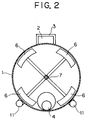
- Figure 2 is an illustrative side sectional view of the present invention.
- Figure 3 is an illustrative view for explaining the diffusion and floating of bubbles in a tank.
- Figure 4 is an illustrative view for explaining the diffusion and floating of bubbles in a prior art sludge recovery tank.
- Figure 1 is an illustrative front view of the interior of a sludge recovery tank 1, and Figure 2 is an illustrative side view of the interior of the sludge recovery tank. In the sludge recovery tank 1, a
sludge recovery port 2 and an intake/exhaust port 3 are provided in an upper portion, and asludge discharge 4 is provided on one end of a bottom portion. Further, a plurality of sludgecoagulant injection nozzles 5 are disposed on a bottom portion of the tank 1 and adapted to be opened to provide ingress of fluid into the tank 1 as illustrated in dotted lines in Figure 3. - In addition, a
rotational shaft 7 with a plurality of connectedagitating blades 6 is transversely installed in the tank 1. - An intake/exhaust pump 8 is connected to the intake/
exhaust port 3 and is capable of rotation for evacuation, i.e. produce a vacuum, so that the interior of the tank 1 is applied with a negative pressure. After that, as asludge suction port 9 of a suction pipe communicated to thesludge recovery port 2 is opened, sludge is sucked into the tank 1 and kept in the negative pressure state. - When the recovered sludge in the tank reaches a specified amount, a
float valve 10 in the tank operates to close thesludge suction port 9, thus stopping introduction of sludge into the tank. - Next, by opening a plurality of sludge
coagulant injection nozzles 5, asuction port 12 of afeed pipe 11 communicated to thenozzle 5 is opened to atmospheric air. As a result, since the intake/exhaust pump 8 is continuously rotated for evacuation, atmospheric air is sucked into the tank 1 kept in the negative pressure state through thesuction port 12. The air sucked into the tank is, as shown in Figure 3, diffused and floated in the sludge as bubbles. The magnitude of the injection force of the atmospheric air can be adjusted according to the viscosity and specific gravity of the sludge. - After the bubbles are checked for diffusion and floating state in the tank, the
suction port 12 of thefeed pipe 11 is opened in thesludge coagulant 13. Thereby, thesludge coagulant 13 is sucked through thefeed pipe 11 and is injected in the tank 1 through thenozzles 5. Then, by opening thesuction port 12 of the feed pipe to the atmospheric air again, the atmospheric air is injected into the tank to generate the diffusion of the bubbles. By concurrently operating theagitating blades 6, the sludge coagulant is mixed and reacts with the sludge. - The rate and direction of rotation of the
agitating blades 6 can be adjusted according to the specific gravity and the viscosity of the sludge. Further, by rotating the agitating flow clockwise or counterclockwise depending on the shapes of the blades, it is possible to exert a mixing reaction between the sludge coagulant and the sludge in the tank 1 up to the corners of the tank along with the diffusion of the bubbles. - After the sludge coagulant is sufficiently mixed and reacted with the sludge (checked through an inspection window not shown) and the sludge in the tank 1 is separated into solid and liquid, the operation of the
agitating blades 6 is stopped. Thesuction port 12 of thefeed pipe 11 is closed, and the intake/exhaust pump 8 is switched to the intake-rotation mode. Thus, air is fed into the tank, and the interior of the tank 1 is pressurized. - The tank 1 is then tilted, and the
sludge discharge port 4 is thus directed downwardly to be opened so that the sludge separated into solid and liquid is forced out from thedischarge port 4 by the inner pressure in the tank. The sludge thus forced out is released and dewatered in a filter apparatus, to be formed into a sludge solid matter which is a practicable form for discarding disposal. - Additionally, when foreign matter entrapped and recovered in the sludge are discharged in the filter apparatus and the like, they tend to damage the filter apparatus. In order to prevent the above damage due to foreign matter,
weir plates 14 for catching the foreign matter before the discharge thereof may be provided in the vicinity of thedischarge port 4. The foreign matter may be taken off through a foreign matter taking-offport 15 provided in the vicinity of theweir plates 14 after discharge of the sludge. - According to the present invention, a plurality of injection nozzles for a sludge coagulant and air are mounted on the bottom of the tank in such a manner as to be opened and to function in a manner illustrated in dotted lines in Figure 3. Thus, by injecting air prior to the injection of sludge coagulant, bubbles diffused in the sludge allow the sludge coagulant to permeate in the depth of the sludge so that the reaction between the sludge coagulant and the sludge is performed through diffusion. Further, after injection of the coagulant, the agitating blades are rotated while the air is injected into the tank again, and thus the sludge coagulant is further mixed and agitated with the sludge. As a result, since the mixing action is enlarged over the whole area of the interior of the tank and the bubbles are floated over the whole area, the reaction between sludge and sludge coagulant is exerted over the whole area of the interior of the tank. This makes it possible to efficiently secure the solid-liquid separation of the sludge in the tank. Further, even when the sludge separated into solid and liquid is discharged from the tank, it can be dewatered by a suitable means, resulting in the solid state being practicable in the discarding disposal of the sludge. Therefore, the present invention has the significant effects.
- The invention has been described in detail with particular emphasis on the preferred embodiments thereof, but it should be understood that variations and modifications within the spirit and scope of the invention may occur to those skilled in the art to which the invention pertains.
Claims (3)
- A solid-liquid separator for sludge comprising:
a sludge recovery tank including a sludge suction port and an intake/exhaust port movable between open and closed positions and provided at an upper portion of said tank, and a sludge discharge port movable between open and closed positions and provided at one end of a bottom portion of said tank;
a plurality of agitating blades capable of being driven in normal and reverse rotations installed in said tank;
a plurality of injection nozzles for a sludge coagulant and air are internally mounted on said bottom portion of said tank in such a manner as to generally enable injection of coagulant and air evenly and into the entire volume of sludge contained in the tank; and
means connecting said intake/exhaust port to an intake/exhaust pump through a float valve. - A solid-liquid separator for sludge comprising:
a sludge recovery tank including first and second end portions and upper and lower portions, a sludge suction port in said tank adapted to be connected to a source of sludge to be treated, an intake/exhaust port provided at an upper portion of said tank, a sludge discharge port movable between open and closed positions and provided in a bottom portion of said tank;
a plurality of agitating blades mounted in said tank for movement therein in a plurality of directions;
a plurality of injection nozzles adapted to inject a sludge coagulant and a gas such as air mounted on the bottom portion of said tank in such manner as to vertically eject coagulant and air into sludge contained within said tank;
a source of pressure and vacuum; and
means connecting said intake/exhaust port to said source of pressure and vacuum. - A method of treating sludge to separate it into a solid phase and a liquid phase including the steps of introducing a given quantity of sludge into a container, producing a vacuum within said container containing said sludge to be treated, alternately injecting a mixture of sludge coagulant and air on the one hand and air only on the other hand into the sludge contained in said container while said container is held under a vacuum, mechanically agitating said mixture of sludge and injected sludge coagulant while holding said chamber under a vacuum, releasing said vacuum in said container and pressurizing said container while providing access of the interior of the container to atmosphere thereby pressure removing the treated sludge from the container.
Applications Claiming Priority (2)
| Application Number | Priority Date | Filing Date | Title |
|---|---|---|---|
| JP107231/93 | 1993-04-12 | ||
| JP5107231A JPH06297000A (en) | 1993-04-12 | 1993-04-12 | Device for separation of solid from liquid in sludge |
Publications (1)
| Publication Number | Publication Date |
|---|---|
| EP0620192A1 true EP0620192A1 (en) | 1994-10-19 |
Family
ID=14453820
Family Applications (1)
| Application Number | Title | Priority Date | Filing Date |
|---|---|---|---|
| EP93119324A Ceased EP0620192A1 (en) | 1993-04-12 | 1993-12-01 | Solid-liquid separator for sludge |
Country Status (4)
| Country | Link |
|---|---|
| US (1) | US5462661A (en) |
| EP (1) | EP0620192A1 (en) |
| JP (1) | JPH06297000A (en) |
| KR (1) | KR970009645B1 (en) |
Cited By (2)
| Publication number | Priority date | Publication date | Assignee | Title |
|---|---|---|---|---|
| CN102167483A (en) * | 2011-01-30 | 2011-08-31 | 北京绿创生态科技有限公司 | stabilization kettle for sludge treatment |
| CN112645422A (en) * | 2021-01-07 | 2021-04-13 | 宋海燕 | Rotatory dispersion's of precipitant sewage sedimentation tank |
Families Citing this family (10)
| Publication number | Priority date | Publication date | Assignee | Title |
|---|---|---|---|---|
| US7020980B1 (en) | 2001-10-13 | 2006-04-04 | Micronics, L.L.C. | Vacuum treatment of waste stream with anti-incrustation measures |
| US6754978B1 (en) | 2001-10-13 | 2004-06-29 | Micronics, L.L.C. | Vacuum treatment of waste stream |
| US7140122B1 (en) | 2001-10-13 | 2006-11-28 | Micronics, Llc | Vacuum treatment of waste stream with anti-incrustation measures |
| US7017277B1 (en) | 2001-10-13 | 2006-03-28 | Adams Randall G | Vacuum treatment of an input stream without ruining delicate output fractions |
| US20050173339A1 (en) * | 2004-02-06 | 2005-08-11 | Sheaffer John R. | Sludge elimination system |
| US20100243558A1 (en) * | 2009-03-25 | 2010-09-30 | Alexander Ekster | Maintaining activated sludge in suspension |
| CN103755120B (en) * | 2014-01-02 | 2015-07-08 | 东南大学 | Airflow harrow type sludge dryer |
| CA3067731A1 (en) | 2017-06-21 | 2018-12-27 | Biovac Solutions Inc. | Apparatus and methods for dewatering sludge |
| CN109499167B (en) * | 2019-01-24 | 2021-03-09 | 陈子仪 | Energy-concerving and environment-protective industrial sewage treatment plant convenient to filter precipitate |
| CN109777729B (en) * | 2019-03-05 | 2022-08-26 | 重庆市农业科学院 | Skid-mounted high-concentration fermentation system |
Citations (5)
| Publication number | Priority date | Publication date | Assignee | Title |
|---|---|---|---|---|
| US2242139A (en) * | 1938-03-25 | 1941-05-13 | Walter C Munroe | Method and apparatus for water purification |
| JPS59102414A (en) * | 1982-12-02 | 1984-06-13 | Hitachi Metals Ltd | Mixing type gravity dehydrator |
| EP0213508A2 (en) * | 1985-08-19 | 1987-03-11 | Peterson Filters Corporation | Method and apparatus for use in separating solids from liquids |
| JPS62197111A (en) * | 1986-02-25 | 1987-08-31 | Kurita Water Ind Ltd | Flocculative reaction tank |
| EP0513352A1 (en) * | 1990-01-29 | 1992-11-19 | SAKURADA, Yasuyuki | Method of cleaning soil water |
Family Cites Families (9)
| Publication number | Priority date | Publication date | Assignee | Title |
|---|---|---|---|---|
| US2415048A (en) * | 1943-04-19 | 1947-01-28 | Sharp William | Equipment for treating sewage |
| US2766203A (en) * | 1953-02-09 | 1956-10-09 | Union Oil Co | Water purification process and apparatus |
| DE2637962C3 (en) * | 1976-08-24 | 1980-07-10 | Electrolux Gmbh, 2000 Hamburg | Process for discharging the waste water from a large number of house connections by means of negative pressure |
| SE421769B (en) * | 1978-01-23 | 1982-02-01 | Evak Sanitaer Ab | VACUUM TOILET DEVICE FOR MOBILE DEVICES |
| US4238338A (en) * | 1979-03-05 | 1980-12-09 | Sanilogical Corporation | Apparatus for the treatment of sewage |
| WO1981000102A1 (en) * | 1979-07-02 | 1981-01-22 | S Small | Waste disposal apparatus |
| US4265753A (en) * | 1980-06-16 | 1981-05-05 | Maylam Manuel | Aeration filtration tank and water treatment system |
| DE3525788A1 (en) * | 1985-06-24 | 1987-01-02 | Escher Wyss Gmbh | Method and arrangement for controlling the addition of chemicals for flocculating flocculable substances in suspensions, especially for purifying the backwater of de-inking installations |
| CA1265267A (en) * | 1985-08-22 | 1990-01-30 | Megill-Stephenson Company Limited (The) | Fluid clarifying assembly |
-
1993
- 1993-04-12 JP JP5107231A patent/JPH06297000A/en active Pending
- 1993-11-25 KR KR1019930025217A patent/KR970009645B1/en active IP Right Grant
- 1993-11-29 US US08/158,617 patent/US5462661A/en not_active Expired - Fee Related
- 1993-12-01 EP EP93119324A patent/EP0620192A1/en not_active Ceased
Patent Citations (5)
| Publication number | Priority date | Publication date | Assignee | Title |
|---|---|---|---|---|
| US2242139A (en) * | 1938-03-25 | 1941-05-13 | Walter C Munroe | Method and apparatus for water purification |
| JPS59102414A (en) * | 1982-12-02 | 1984-06-13 | Hitachi Metals Ltd | Mixing type gravity dehydrator |
| EP0213508A2 (en) * | 1985-08-19 | 1987-03-11 | Peterson Filters Corporation | Method and apparatus for use in separating solids from liquids |
| JPS62197111A (en) * | 1986-02-25 | 1987-08-31 | Kurita Water Ind Ltd | Flocculative reaction tank |
| EP0513352A1 (en) * | 1990-01-29 | 1992-11-19 | SAKURADA, Yasuyuki | Method of cleaning soil water |
Non-Patent Citations (2)
| Title |
|---|
| DATABASE WPI Section Ch Week 8430, 13 June 1984 Derwent World Patents Index; Class D04, AN 84-184653 * |
| PATENT ABSTRACTS OF JAPAN vol. 12, no. 50 (C - 476) 16 February 1988 (1988-02-16) * |
Cited By (2)
| Publication number | Priority date | Publication date | Assignee | Title |
|---|---|---|---|---|
| CN102167483A (en) * | 2011-01-30 | 2011-08-31 | 北京绿创生态科技有限公司 | stabilization kettle for sludge treatment |
| CN112645422A (en) * | 2021-01-07 | 2021-04-13 | 宋海燕 | Rotatory dispersion's of precipitant sewage sedimentation tank |
Also Published As
| Publication number | Publication date |
|---|---|
| JPH06297000A (en) | 1994-10-25 |
| US5462661A (en) | 1995-10-31 |
| KR970009645B1 (en) | 1997-06-17 |
Similar Documents
| Publication | Publication Date | Title |
|---|---|---|
| US5462661A (en) | Solid-liquid separator for sludge | |
| US4919826A (en) | Process and apparatus for separating solids and liquids from an effluent stream | |
| JPH06198151A (en) | Method and device for dispersing gas in liquid or slurry | |
| WO1992017260A1 (en) | Material treatment apparatus | |
| JPH0947647A (en) | Flow plate rotating type mixing and defoaming device | |
| RU2587059C2 (en) | Methods of filling and emptying ball mill with mixer by moving auxiliary crushing bodies by means of hydraulic transporting medium | |
| US5017016A (en) | Method of processing asbestos chips and apparatus | |
| JP2006027012A (en) | Defoaming method and defoaming apparatus therefor | |
| JP4011955B2 (en) | Table feeder and wastewater, sludge and liquid waste treatment system equipped with table feeder | |
| JPS61258712A (en) | Mixing head for reaction injection molding apparatus | |
| US6021787A (en) | Method for cleaning vessels during service | |
| JP2705803B2 (en) | Method and apparatus for collecting and solidifying asbestos waste | |
| CN212238609U (en) | Device for continuously repairing polluted soil by supercritical carbon dioxide extraction | |
| CN209753648U (en) | Integrated form soil heavy metal drip washing system | |
| JPS5855012A (en) | Solid-liquid separating device of slurry | |
| WO1996023581A1 (en) | Slurry forming process and slurry transfer and densification through vacuum pumping | |
| JP3654106B2 (en) | Liquid injection method and liquid injection device | |
| CN215656267U (en) | Powder particle separator | |
| GB2090240A (en) | The treatment of liquid suspensions | |
| JPH05317610A (en) | Sludge sucking device and system using the same | |
| CN220597101U (en) | Bubble drainage purifier | |
| JPH0377400B2 (en) | ||
| CN212999446U (en) | Preparation device of high-efficiency ring composite desulfurizer | |
| CN219010108U (en) | Sewage neutralization and recycling device system | |
| JP4371439B2 (en) | Specific gravity separator for waste plastic |
Legal Events
| Date | Code | Title | Description |
|---|---|---|---|
| PUAI | Public reference made under article 153(3) epc to a published international application that has entered the european phase |
Free format text: ORIGINAL CODE: 0009012 |
|
| AK | Designated contracting states |
Kind code of ref document: A1 Designated state(s): DE FR GB IT |
|
| 17P | Request for examination filed |
Effective date: 19950204 |
|
| GRAG | Despatch of communication of intention to grant |
Free format text: ORIGINAL CODE: EPIDOS AGRA |
|
| 17Q | First examination report despatched |
Effective date: 19961120 |
|
| STAA | Information on the status of an ep patent application or granted ep patent |
Free format text: STATUS: THE APPLICATION HAS BEEN REFUSED |
|
| 18R | Application refused |
Effective date: 19970509 |