EP0620139B1 - Reaktionsgehäuse eines aufblasbaren Rückhaltesystems mit integriertem Ausblasvorrichtungsraum - Google Patents
Reaktionsgehäuse eines aufblasbaren Rückhaltesystems mit integriertem Ausblasvorrichtungsraum Download PDFInfo
- Publication number
- EP0620139B1 EP0620139B1 EP19940302028 EP94302028A EP0620139B1 EP 0620139 B1 EP0620139 B1 EP 0620139B1 EP 19940302028 EP19940302028 EP 19940302028 EP 94302028 A EP94302028 A EP 94302028A EP 0620139 B1 EP0620139 B1 EP 0620139B1
- Authority
- EP
- European Patent Office
- Prior art keywords
- body part
- air bag
- reaction canister
- inflator
- gas
- Prior art date
- Legal status (The legal status is an assumption and is not a legal conclusion. Google has not performed a legal analysis and makes no representation as to the accuracy of the status listed.)
- Expired - Lifetime
Links
- 238000006243 chemical reaction Methods 0.000 title claims description 87
- 238000002360 preparation method Methods 0.000 claims description 36
- 239000000463 material Substances 0.000 claims description 28
- 238000004519 manufacturing process Methods 0.000 claims description 14
- 230000001681 protective effect Effects 0.000 claims description 13
- 238000001816 cooling Methods 0.000 claims description 11
- 238000001125 extrusion Methods 0.000 claims description 10
- 229910052782 aluminium Inorganic materials 0.000 claims description 8
- XAGFODPZIPBFFR-UHFFFAOYSA-N aluminium Chemical compound [Al] XAGFODPZIPBFFR-UHFFFAOYSA-N 0.000 claims description 8
- 239000004020 conductor Substances 0.000 claims description 8
- 238000013022 venting Methods 0.000 claims description 6
- 210000002268 wool Anatomy 0.000 claims description 5
- 238000009751 slip forming Methods 0.000 claims description 2
- 238000002485 combustion reaction Methods 0.000 claims 1
- 239000007789 gas Substances 0.000 description 72
- 230000006378 damage Effects 0.000 description 13
- 238000009434 installation Methods 0.000 description 10
- 238000013461 design Methods 0.000 description 8
- 238000000034 method Methods 0.000 description 7
- 230000007935 neutral effect Effects 0.000 description 7
- 238000010348 incorporation Methods 0.000 description 6
- 230000000712 assembly Effects 0.000 description 5
- 238000000429 assembly Methods 0.000 description 5
- 239000012530 fluid Substances 0.000 description 5
- 208000027418 Wounds and injury Diseases 0.000 description 4
- 239000011324 bead Substances 0.000 description 4
- 238000010276 construction Methods 0.000 description 4
- 208000014674 injury Diseases 0.000 description 4
- 230000001921 mouthing effect Effects 0.000 description 4
- 230000015572 biosynthetic process Effects 0.000 description 3
- 230000000694 effects Effects 0.000 description 3
- 230000006872 improvement Effects 0.000 description 3
- 229910052751 metal Inorganic materials 0.000 description 3
- 239000002184 metal Substances 0.000 description 3
- 230000008569 process Effects 0.000 description 3
- 238000003466 welding Methods 0.000 description 3
- 229910000831 Steel Inorganic materials 0.000 description 2
- 230000008901 benefit Effects 0.000 description 2
- 238000005520 cutting process Methods 0.000 description 2
- 238000009826 distribution Methods 0.000 description 2
- 239000000835 fiber Substances 0.000 description 2
- 230000000977 initiatory effect Effects 0.000 description 2
- 238000003780 insertion Methods 0.000 description 2
- 230000037431 insertion Effects 0.000 description 2
- 230000014759 maintenance of location Effects 0.000 description 2
- 230000013011 mating Effects 0.000 description 2
- 239000000203 mixture Substances 0.000 description 2
- 239000000123 paper Substances 0.000 description 2
- 230000002093 peripheral effect Effects 0.000 description 2
- 239000010959 steel Substances 0.000 description 2
- 229910001111 Fine metal Inorganic materials 0.000 description 1
- 229910000760 Hardened steel Inorganic materials 0.000 description 1
- FYYHWMGAXLPEAU-UHFFFAOYSA-N Magnesium Chemical compound [Mg] FYYHWMGAXLPEAU-UHFFFAOYSA-N 0.000 description 1
- 239000004775 Tyvek Substances 0.000 description 1
- 229920000690 Tyvek Polymers 0.000 description 1
- 230000004308 accommodation Effects 0.000 description 1
- 230000001066 destructive effect Effects 0.000 description 1
- 238000009792 diffusion process Methods 0.000 description 1
- 238000006073 displacement reaction Methods 0.000 description 1
- 239000002360 explosive Substances 0.000 description 1
- 239000011888 foil Substances 0.000 description 1
- 238000009472 formulation Methods 0.000 description 1
- 239000004615 ingredient Substances 0.000 description 1
- 239000002655 kraft paper Substances 0.000 description 1
- 230000000670 limiting effect Effects 0.000 description 1
- 229910052749 magnesium Inorganic materials 0.000 description 1
- 239000011777 magnesium Substances 0.000 description 1
- 238000012986 modification Methods 0.000 description 1
- 230000004048 modification Effects 0.000 description 1
- 239000004033 plastic Substances 0.000 description 1
- 230000009467 reduction Effects 0.000 description 1
- 230000002829 reductive effect Effects 0.000 description 1
- 230000004044 response Effects 0.000 description 1
- 230000000452 restraining effect Effects 0.000 description 1
- 230000002441 reversible effect Effects 0.000 description 1
- 238000000926 separation method Methods 0.000 description 1
- 230000007480 spreading Effects 0.000 description 1
- 238000003892 spreading Methods 0.000 description 1
- 238000003860 storage Methods 0.000 description 1
- 229920001169 thermoplastic Polymers 0.000 description 1
- 239000004416 thermosoftening plastic Substances 0.000 description 1
- 230000008719 thickening Effects 0.000 description 1
- 239000013585 weight reducing agent Substances 0.000 description 1
Images


Classifications
-
- B—PERFORMING OPERATIONS; TRANSPORTING
- B60—VEHICLES IN GENERAL
- B60R—VEHICLES, VEHICLE FITTINGS, OR VEHICLE PARTS, NOT OTHERWISE PROVIDED FOR
- B60R21/00—Arrangements or fittings on vehicles for protecting or preventing injuries to occupants or pedestrians in case of accidents or other traffic risks
- B60R21/02—Occupant safety arrangements or fittings, e.g. crash pads
- B60R21/16—Inflatable occupant restraints or confinements designed to inflate upon impact or impending impact, e.g. air bags
- B60R21/20—Arrangements for storing inflatable members in their non-use or deflated condition; Arrangement or mounting of air bag modules or components
- B60R21/217—Inflation fluid source retainers, e.g. reaction canisters; Connection of bags, covers, diffusers or inflation fluid sources therewith or together
- B60R21/2171—Inflation fluid source retainers, e.g. reaction canisters; Connection of bags, covers, diffusers or inflation fluid sources therewith or together specially adapted for elongated cylindrical or bottle-like inflators with a symmetry axis perpendicular to the main direction of bag deployment, e.g. extruded reaction canisters
-
- B—PERFORMING OPERATIONS; TRANSPORTING
- B60—VEHICLES IN GENERAL
- B60R—VEHICLES, VEHICLE FITTINGS, OR VEHICLE PARTS, NOT OTHERWISE PROVIDED FOR
- B60R21/00—Arrangements or fittings on vehicles for protecting or preventing injuries to occupants or pedestrians in case of accidents or other traffic risks
- B60R21/02—Occupant safety arrangements or fittings, e.g. crash pads
- B60R21/16—Inflatable occupant restraints or confinements designed to inflate upon impact or impending impact, e.g. air bags
- B60R21/20—Arrangements for storing inflatable members in their non-use or deflated condition; Arrangement or mounting of air bag modules or components
- B60R21/201—Packaging straps or envelopes for inflatable members
-
- B—PERFORMING OPERATIONS; TRANSPORTING
- B60—VEHICLES IN GENERAL
- B60R—VEHICLES, VEHICLE FITTINGS, OR VEHICLE PARTS, NOT OTHERWISE PROVIDED FOR
- B60R21/00—Arrangements or fittings on vehicles for protecting or preventing injuries to occupants or pedestrians in case of accidents or other traffic risks
- B60R21/02—Occupant safety arrangements or fittings, e.g. crash pads
- B60R21/16—Inflatable occupant restraints or confinements designed to inflate upon impact or impending impact, e.g. air bags
- B60R21/26—Inflatable occupant restraints or confinements designed to inflate upon impact or impending impact, e.g. air bags characterised by the inflation fluid source or means to control inflation fluid flow
- B60R21/276—Inflatable occupant restraints or confinements designed to inflate upon impact or impending impact, e.g. air bags characterised by the inflation fluid source or means to control inflation fluid flow with means to vent the inflation fluid source, e.g. in case of overpressure
Definitions
- This invention relates generally to inflatable passive restraint systems such as used in motor vehicles to restrain the movement of a seated occupant during a collision.
- One aspect of the invention is more particularly directed to an improvement in the design of an air bag module used in such restraint systems to minimize deformation of the module and possible damage to the dashboard and/or instrument panel of a vehicle with the deployment of the air bag.
- Such improvement is in the structure internal to the module for a) housing and positioning the inflator and the air bag and b) directing the inflating gas flow or jet for best deployment of the air bag.
- the invention more particularly relates to an improvement in the structure used in such systems for housing a gas generation material and an inflatable bag to further reduce the weight of the assembly and to permit the more effective and economical incorporation therein of various design features.
- the words “forwardly” and “rearwardly” refer to the normal forward and reverse directions of travel of the vehicle to which a passenger passive restraint module is attached.
- the phrase “thrust neutral” refers to the production by an inflator of zero thrust when initiated as, for example, during a deployment event or accidentally such as during shipping, storage, or handling thereof. That is to say, the gas discharge openings in the inflator are so positioned that the gas is discharged in opposing directions whereby there are no resulting forces tending to cause physical movement of the inflator. Hence, the inflator will expend the energy generated thereby, generally in place.
- the Oldberg et al. patent discloses a safety device for providing protection for vehicle passengers comprising a folded inflatable crash bag closely surrounding an elongated cylindrical diffuser member, being secured thereto by clamps.
- the diffuser member defines a chamber in which an inflator comprising a fluid reservoir in an inner container is concentrically located.
- the inner container is seam welded at the opposite ends thereof to the diffuser member.
- the inflator poses a large potential hazard. Accidental initiation thereof during shipping, storing and installation in the safety device could result in injury to personnel and also cause property damage, particularly when the inflator is not of the thrust neutral type. Thus, in order to minimize the possibility of such injury and damage, it is desirable to reduce the amount of handling to which the inflator is subjected during the fabrication and assembly of the safety device. Installation of the inflator as a last operation in the assembly of the device would provide a substantial reduction in the risk of injury and damage. With the use of an inflator of the thrust neutral type, the risk of such injury and damage would be further reduced.
- the construction of the Oldberg et al. safety device is such as to preclude installation of the inflator as a last operation of the assembly of the device.
- the inflatable bag is provided in closely surrounding relation to the diffuser member, with the inflator, that is, the inner container, welded at the ends thereof to the diffuser member.
- the inflator that is, the inner container, welded at the ends thereof to the diffuser member.
- the Hurley et al. patent discloses a folded inflatable bag surrounding a gas generator having a head assembly of cylindrical shape provided with a closed end and an open aft end that is closed by a closure plate. A centrally positioned orifice that is normally closed by a rupture disc is provided in the closure plate. Enclosing the cylindrical portion of the head assembly is a concentrically positioned diffuser having a closed end in the shape of a dished head, thereby providing an annular cavity about the gas generator.
- the rupture disc Upon initiation of the gas generator, the rupture disc releases, in response to pressure in the head assembly exceeding the burst pressure of the disc, thereby allowing the generated gas to flow out of the orifice in the closure plate of the aft end of the gas generator and to impinge on the inner wall at the end of the diffuser. This causes the gas to be dispersed into the annular cavity and out of a plurality of openings spaced around the wall of the diffuser. With the generated gas flowing out of the aft end of the gas generator, the operation thereof is not thrust neutral. Nor does the Hurley construction allow fabrication of the device with the installation of the gas generator as a last operation of the assembly.
- the Thorn et al. patent discloses a folded inflatable bag positioned in close contact with an elongated cylindrical gas generator.
- the gas generator is provided with rows of gas outlet ports that extend 360° around the cylinder.
- the gas is discharged in opposing directions and produces counteracting thrusts, and thus, is thrust neutral.
- a gas redirecting plate in the shape of a half cylindrical container is positioned in spaced relation around the forwardly facing portion of the gas generator. The plate redirects forwardly discharged inflating gas in a rearward direction into the inflatable bag.
- Redirected gas together with gas that directly is discharged into the inflatable bag deploy the bag, which normally is folded, to an inflated condition. In the stored position thereof, the bag is positioned closely adjacent to and in contact with the rearward half side of the gas generator. This precludes installation of the gas generator as a last operation in the assembly of the apparatus.
- the Smith patent discloses an inflatable restraint system including a folded inflatable cushion, a concentric elongated cylinder inflator-diffuser combination, and an elongated horizontally orientated nozzle.
- the inflator and diffuser are located within the confines of the folded cushion and are connected as a unit to the side walls of a housing therefor by means of bolts which extend into tapped bosses, which bosses are rigid with the combined unit. Consequently, neither the combined unit, nor the inflator can be installed as a last operation in the assembly of the system.
- an elongated cylindrical inflator and a folded air bag are mounted in a rigid reaction canister which is fixed to the dashboard of a vehicle, with the orientation and arrangement of gas discharge openings or exhaust ports in the inflator being such that, when activated, an initial flow generated gas is directed rearwardly by the inflator to inflate the bag. Excess gas flows from the inflator in a forward direction into the surrounding environment.
- This result is achieved by using rupturable foil layers to close both forwardly and rearwardly directed inflator exhaust ports, with rupturing of the rearwardly directed ports occurring at a pre-selected pressure that is lower than the pressure at which the forwardly directed ports rupture.
- the inflator is not thrust neutral, nor is it capable of installation as a last operation of the assembly of the apparatus because of the positioning in the reaction canister of the folded air bag in close proximity to the inflator.
- the container is generally referred to as a reaction canister and provides a medium for installing and retaining a module in the instrument panel by the utilization of suitable brackets.
- the reaction canister provides protection for the inflator, the diffuser, if provided, and the air bag until the time of deployment of the bag. Additionally, the reaction canister absorbs the loads that are produced upon deployment of the bag, which loads, typically, are large. Unless sufficiently absorbed, such loads can cause serious damage to the interior of the vehicle, and in particular, to the instrument panel.
- a drawback to the use of a reaction canister in an air bag module for passenger protection is the envelope in the dashboard or instrument panel that is allotted for the installation of the module. Resulting restrictions, usually in height, causes lengthened, that is, deeper, top and bottom panels in order to accommodate the folded volume of the air bag. The bag is then restricted for unfolding and must travel rearwardly a distance greater than desirable before unfolding. Because of the large amount of gas that is produced and the distance the bag needs to travel before unfolding, pressure builds up in the reaction canister to a level that tends to expand the canister and cause it to bulge. This condition, known as bell mouthing, is very destructive of the instrument panel, and is particularly objectionable in low speed crashes where other damage to the vehicle is small.
- the Zionmek et al. patent and the Lauritzen et al. patent disclose the use of a tether strap to resist the spreading forces on the reaction canister and thereby preclude bell mouthing upon deployment of the air bag. This technique allows the use of lighter weight and less expensive reaction canisters.
- the structural arrangement leaves something to be desired in respect of the introduction of undesirable complication into the manufacturing and assembling operations, and moreover, does not allow installation of the inflator as a last operation in the assembly of the module.
- the Kraft et al patent discloses a vehicle occupant restraint system in which an airbag is folded into the mouth of a reaction canister inside which a separate inflator is situated.
- the inflator comprises a body with a cylindrical recess in which gas generant material is situated and an adjacent chamber containing two filters through which hot gases flow upon actuation of the inflator.
- Patent EP-A-0 558 240 claims a priority date of 24 February 1992, was published on 1 September 1993 and is accordingly prior art under the provisions of EPC Article 54(3) for the purposes of novelty only.
- This patent discloses a vehicle occupant restraint system having an extruded reaction canister which has integrally formed therewith an enclosed tubular diffuser tube.
- a separate inflator having a body adapted to withstand the high pressure which is produced by the ignition of gas generant material contained therein is positioned inside the integrally formed diffuser tube.
- air bag module assemblies of the prior art generally include three basic components: 1) a cushion or air bag that is inflated with gas such as when the vehicle encounters a sudden deceleration, 2) an inflator which upon actuation serves to provide the gas used to inflate the air bag, and 3) a reaction canister which typically functions as a structural housing supporting both the inflator and the air bag while providing a mounting base for installation of the assembly in a vehicle and direction to the gas resulting from the inflator.
- the walls of such inflators are typically fabricated of relatively thick material to provide additional strength thereto.
- the inflator is typically housed within a walled reaction canister. The use of such thick walled inflators housed within a walled reaction housing typically results in an assembly of greater weight than is optimally desired.
- reaction canisters are commonly fabricated using formed and/or welded steel, such fabrication techniques are not conducive to the economical and effective incorporation therein of various desired features, such as various mounting or attachment preparations, for example, in particular vehicular inflatable restraint system design applications.
- a general object of another aspect of the invention is to provide an improved structure for use in housing a gas generant material and in housing and positioning an inflatable bag in an inflatable passive restraint system.
- Another object of the invention is to provide a reaction canister structure having an integral chamber for housing a gas generant material.
- a more specific objective of this aspect of the invention is to overcome one or more of the problems described above.
- the general object of this aspect of the invention can be attained, at least in part, through a specifically shaped and/or formed body part for an inflatable passive restraint system reaction canister.
- the body part is formed by extrusion and is trough-shaped.
- the body part includes first and second opposite side walls and an integrally shaped inflator chamber having gas exit vents along at least one side thereof.
- the body part has first and second opposite ends with a plurality of end closure attachment preparations at each of the opposite ends.
- the air bag module assemblies of the prior art generally include a thick walled inflator housed within a walled reaction canister and thereby undesirably increase the weight of the assembly. Further, the fabrication of reaction canisters using conventional machine tooling operations is not conducive to the economical and effective incorporation of various desired features, such as various mounting or attachment preparations, for example, in particular vehicular inflatable restraint system design applications.
- the invention further comprehends a reaction canister for an inflatable passive restraint system.
- the reaction canister includes a specifically shaped and/or formed body part having first and second opposite side walls and an integrally shaped inflator chamber having gas exit vents along at least one side of the chamber.
- the body part further includes first and second opposite ends with a plurality of end closure attachment preparations at each of the said opposite ends.
- the reaction canister further includes first and second end closures attached to a respectively associated opposite end of the body part by means positioned in cooperative relation with the respective end closure attachment preparations.
- Each end closure further include an inflator chamber base portion positioned to receive an associated one of the ends of the integrally shaped inflator chamber of the body part.
- the invention still further comprehends a reaction canister for an inflatable passive restraint system comprising an extruded aluminum trough-shaped body part, an air bag retainer/diffuser attached to the reaction canister body part, and first and second end closures.
- the body part includes first and second opposite side walls and an integrally shaped inflator chamber having gas exit vents along at least one side thereof.
- the body part further includes at least one integrally formed mounting portion of an external type for mounting of the reaction canister body part into a vehicle.
- the body part has first and second opposite ends with a plurality of end closure attachment preparations at each opposite end. Further, at least one of the side walls is formed continuously with the integrally shaped inflator chamber via a side wall connecting portion forming at least one gas cooling cavity therein.
- the side wall connecting portion includes at least one vent hole to permit venting of gas from the reaction canister and the gas cooling cavity contains a thermal conductive material of aluminum wool to facilitate cooling of vented gas.
- the reaction canister body part additionally includes at least one attachment sleeve preparation adapted for the attachment of the air bag retainer/diffuser to the reaction canister body part.
- the air bag retainer/diffuser is attached to the reaction canister body part by insert means positioned in cooperative relation with the attachment sleeve preparation.
- the first and second end closures are attached to a respectively associated opposite end of the body part by screw means positioned in cooperative relation with the respective end closure attachment preparations.
- Each of the first and second end closures further having an inflator chamber base portion positioned to receive an associated one of the ends of the integrally shaped inflator chamber of the body part, wherein at least one of the end closures includes an end plate and an end base.
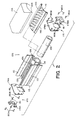
- FIGS. 1- 3 illustrate another aspect of the invention.
- These figures illustrate an extruded reaction canister or, more briefly, can body part, generally designated by the reference numeral 100, which includes the general form of a long, narrow, open receptacle or trough.
- the reaction canister body part 100 is shown separately in FIG. 1 and as a part of an air bag module assembly, generally designated by the reference numeral 105, in FIGS. 2 and 3.
- the reaction canister body part 100 includes an integrally shaped inflator chamber 106 having an exterior surface 107 and an interior surface 108 and, like inflator chambers that are commonly included in inflators designed and used in air bag module assemblies, can serve to house a gas generant material, such as commonly associated with pyrotechnic inflators, such as a gas generant pack 109, as shown in FIG. 2.
- a gas generant material such as commonly associated with pyrotechnic inflators, such as a gas generant pack 109, as shown in FIG. 2.
- inflator chamber in the form of a tube having a circular cross section will generally be preferred as such a structure is generally best suited for use in such applications wherein the chamber must withstand such pressure operation. It is to be understood, however, that in the practice of the invention, if desired, other shapes or forms of inflator chamber can be used.
- the internal components of the inflator chamber 106 and the composition and form of the gas generant material housed therein form no part of the present invention and may be any of a number of known constructions/formulations such as are commercially available. As discussed above and by way of example and not limitation, such internal components may comprise that disclosed in commonly assigned U.S. Patent No. 4,890,860 granted to F. E. Schneiter on January 2, 1990.
- the reaction canister body part 100 includes first and second opposite side walls or panels, e.g., a top side wall and a bottom side wall, 110 and 112, respectively, and first and second opposite ends, 114 and 115, respectively.
- the side walls can, for example, be formed directly continuous with the integrally shaped inflator chamber 106 or, as shown, continuously formed therewith via side wall connecting portions 116 and 118, respectively.
- the side walls 110 and 112, respectively, can generally be spaced apart so as to form an air bag retaining cavity, generally designated by the reference numeral 120, therebetween.
- the spaced apart side walls are generally parallel to each other, ensuring a more uniformly shaped air bag retaining cavity and thereby reducing the possibility of the air bag housed within the cavity therebetween undesirably getting caught or snagged such as by a protruding surface or edge of the reaction canister body part.
- the side walls can be otherwise angularly positioned relative to one another as may be desired in specific applications, such as to permit the accommodation of the reaction canister into a specifically shaped dash board or instrument panel opening.
- the side walls 110 and 112 are shown as being of different lengths, with the bottom side wall 112 being of a longer length than the top side wall 110.
- reaction canisters so shaped can more conveniently be incorporated within the dash board/instrument panel of most common automotive vehicles. It is to be understood, however, that the invention is not limited to use in conjunction with reaction canister side walls of such relative length. That is, the invention can similarly be used in conjunction with reaction canister body parts having side walls of similar lengths as well as reaction canister body parts wherein the length of the top side wall exceeds that of the bottom side wall.
- the inflator chamber 106 includes gas exit vents or ports 126 along a side 130 thereof. Such gas exit vents permit the gas generated within the inflation chamber to exit from the chamber and be directed for inflation of an air bag 134, as can more easily be seen by reference to FIGS. 2 and 3.
- one or more flow directing devices can be incorporated within the reaction canister assembly.
- flow directing devices can take the shape or form of baffles or gas port passages of particular size, shape and/or arrangement.
- such flow directing devices can take the form of and/or include an air bag retainer/diffuser device 140, as shown in FIGS. 2 and 3.
- the air bag retainer/diffuser device 140 includes a plurality of openings 141 therein to permit the passage of gas therethrough.
- the openings 141 are located and sized so as to provide a desired distribution of gas into the air bag 134.
- a preferred such device or system for use in the practice of the invention is a retainer device/system incorporating a diffuser the size, geometry, and arrangement of the gas passage openings in which can be appropriately designed to satisfy specific application needs and the invention is not necessarily limited to use with a diffuser with gas passage openings of any specific configuration.
- a diffuser device/system in addition to fostering desired gas diffusion can also assist in: 1) facilitating module assembly; 2) maintaining proper air bag retention within the assembly, and 3) maintaining desired separation of the hot inflator surfaces from both the surface of the air bag as well as from contact by the vehicle occupants
- a means of retaining an air bag can advantageously avoid or minimize the need for conventional fastener devices such as screws or rivets, for example.
- a diffuser device/system such as the diffuser 140, can serve to facilitate control of bell mouthing of the reaction canister, thereby assisting in maintaining the integrity of the reaction canister.
- the reaction canister body part 100 includes, as a part of the side walls 110 and 112, integrally formed attachment sleeves 142.
- attachment sleeves allow for the fastenerless attachment of an air bag within an inflatable safety system. It is to be understood, however, that the practice of the subject invention in its broader aspects is not limited to use with attachment sleeves and that, if desired, an alternative form of air bag retention/diffuser attachment preparation can be used, such as those that include fastener devices such as screws or rivets, for example.
- the invention can be practiced via the utilization of a cushion retainer, which device serves to retain an air bag (e.g., a cushion) within the assembly while minimizing or, preferably, avoiding the use of fasteners such as screws or rivets, but which in this case does not necessarily incorporate diffuser features therein. Also, it is to be understood that, if desired, the invention can be practiced both without the utilization of the referenced diffuser features and while making use of common forms of air bag attachment, such as the use of fasteners such as screws and/or rivets, for example.
- a cushion retainer which device serves to retain an air bag (e.g., a cushion) within the assembly while minimizing or, preferably, avoiding the use of fasteners such as screws or rivets, but which in this case does not necessarily incorporate diffuser features therein.
- the invention can be practiced both without the utilization of the referenced diffuser features and while making use of common forms of air bag attachment, such as the use of fasteners such as screws and/or rivets, for example.
- air bags in inflatable restraint systems can include one or more vent holes (not shown) therein whereby gases, such as produced via a gas generant material such as housed within the inflator chamber 106, can desirably be vented out of the air bag.
- gases such as produced via a gas generant material such as housed within the inflator chamber 106
- Such air bag vent holes can advantageously assist in post deployment venting of the air bag both immediately after a crash event (e.g., as may be desired to soften the bag upon contact by a vehicle occupant thereby resulting in a greater cushioning effect and to reduce the likelihood or extent of rebound by such vehicle occupant upon such contact) and subsequent thereto (e.g., such as may be desired to facilitate the exiting from the vehicle by the occupant subsequent to the deployment event).
- the air bag 134 has a thickened peripheral edge 143.
- Such thickening of an air bag can take the form, as shown, of a hemmed loop 144 of air bag material at the gas inlet opening edge of the air bag into which a selected bead material 145 is placed to better ensure positive engagement of the air bag 134 into the assembly 105.
- the air bag retainer/diffuser device 140 includes a channel 146 thereabout into which channel the thickened peripheral edge of the air bag can be inserted so as to be in cooperative relation with said attachment sleeve preparation and thus secured to form an air bag/diffuser subassembly for joinder to the reaction canister body part, as shown and as described in detail in the above-referenced patent applications.
- the bead material can suitably be fabricated from a wide range of materials such as metal or, preferably, plastic, especially an extruded thermoplastic and can take various shapes or forms to meet the needs of particular applications.
- the illustrated reaction canister body part 100 further includes canister vent holes 149 about the side wall connecting portions 116 and 118, respectively (see FIG. 3).
- canister vent holes allow for "behind the bag venting", whereby gas is vented from the canister in a rearward fashion thereby minimizing the likelihood of contact between the vented gas and the vehicle occupant.
- canister vent holes permit a leveling off the breakout pressure, e.g., the pressure at which an air bag initially being deployed breaks out through the cover layer of the assembly, such as from the air bag retaining cavity and into the interior of the vehicle, for example.
- the reaction canister body part 100 forms gas cooling cavities 150 wherein vented gases can suitably be cooled.
- a thermal conductive material 151 can be placed within the cooling cavities 150 to assist in the cooling of, e.g., removal of heat from, the gases vented out from the air bag.
- a thermal conductive material preferably has a large surface and is capable of absorbing large amounts of heat while permitting the vented gas to be passed therethrough.
- the so positioned thermal conductive material thus functions to assist in retaining generated or resulting heat within the confines of the reaction canister and thus away from the vehicle occupant.
- such a thermal conductive material can take the form of a metallic wool such as steel wool or, more preferably, due to the relatively greater heat conducting ability and lighter weight of aluminum, an aluminum wool.
- the body part further includes protective cover retaining preparations 152, shown as taking the form of slots about the outer extremity of each of the side walls 110 and 112, respectively.
- a protective cover 154 such as of fiber reinforced paper, for example, can be included as a part of the air bag module assembly 105 in the form of a wrap joined to the reaction canister body part 100 about the air bag 134 within the air big retaining cavity 120 of the assembly.
- Such a protective cover 154 can be secured to the reaction canister body part 100 such as with an elastic band or other selected bead material 158 placed about the outer edge 160 of the protective cover 154, with the bead material secured within such a protective cover retainer slot preparation 152.
- Such a protective cover serves to help protect the air bag from damage such as by accidental or other undesired contact such as by or with other elements of the inflatable restraint system as well as extraneous elements in the environment to which the air bag can be exposed. Also, such a protective cover serves to desirably keep debris out of the reaction canister assembly.
- such a protective cover is preferably fabricated of a tough, wear resistant material which, while normally tear resistant, can be preferably broken or ruptured at predetermined or selected sites such as through the aid of perforations therein.
- a protective cover can be fabricated of fiber reinforced paper, such as that sold by E.I. Du Pont de Nemours Co. under the name TYVEK. It is to be understood, however, that other appropriate materials such as having such described or preferred properties or characteristics can also be used.
- the reaction canister body part 100 includes a plurality of end closure attachment preparations 164.
- Such attachment preparations can take the form of a hollow or, as the body part is preferably prepared by extrusion fabrication, such attachment preparations can preferably take the form of a groove or what is commonly referred to in the extrusion field as a "screw slot.” It is to be understood, however, that the attachment preparations and the form of attachment are not limited to the use of screw fasteners.
- attachment preparations 164 are preferably spaced about the periphery of the body part 100, both along the side walls 110 and 112, and about the inflator chamber 106, preferably about the exterior surface 107 thereof, so as to ensure secure attachment of end closures 170 (see FIG. 2) to the reaction canister body part 100 and preferably at least at each of the opposite ends 114 and 115 thereof.
- the end closures 170 retain the cross sectional shape of the reaction canister body part 100.
- the end closures can take the form of end plates such as with an integral inflator chamber base or, as may be preferred and as is shown in FIG. 2, a combination of end plates 174 (individually designated as 174A and 174B, respectively) and end bases 178 (individually designated as 178A and 178B, respectively).
- fasteners 180 such as swaging screw fasteners, such as made of appropriately hardened steel and which permits use in such pressure applications, can be used in securing such end closures in the assembly. Further, in one preferred embodiment of the invention and as illustrated in FIGS.
- the fasteners denominated 180A are used in simultaneously securing both end plates and end bases, while the fasteners denominated 180B are used to secure end plates and not end bases.
- the end plates 174 primarily serve to enclose the ends of the air bag retaining cavity formed by the reaction canister body part 100
- the end bases 178 primarily serve to enclose the ends of the integral inflator chamber 106 formed in the reaction canister body part 100 of the invention.
- the end bases 178 include a mating face 181 which upon assembly mates with the integral inflator chamber 106. That is, the mating face 181 properly receives one of the ends of the integrally shaped inflator chamber 106 to provide closure to the chamber 106.
- end bases comprising thicker and/or stronger materials than used in the end plates will typically be preferred as the end closures at the inflator chamber will typically be subjected to significantly greater pressures than the end closures of the air bag retaining cavity.
- the attachment preparations used for securing such end bases to the assembly typically must be able to withstand such significantly greater pressures.
- the end closure attachment preparations for use in attaching such end bases to the reaction canister body part e.g., the end closure attachment preparations designated 164A and generally in the form of four screw slots relatively equally spaced about the exterior surface 107 of the inflator chamber 106, and the fasteners used in combination therewith, i.e., the fasteners 180A, are of both a larger diameter and the fasteners are of a greater length than the end closure attachment preparations and fasteners, i.e., the preparations 164B and the fasteners 180B, that are used solely in securing end plates 174 to the reaction canister body part 100.
- Such a system and method of end closure attachment provides a relatively inexpensive, yet secure system and method for attaching end closures within the assembly to the reaction canister body part of the invention.
- the reaction canister body part 100 can also include one or more mounting portions, generally designated by the reference numeral 184.
- Such mounting portions can be either of an external type, i.e., for mounting of the reaction canister body part within a selected vehicle, or an internal or semi-internal type, i.e., for mounting of items to or within the reaction canister body part.
- an external mounting portion such as the mounting bracket 184A, can be appropriately positioned, orientated, shaped, and sized as desired to effect the desired result.
- an internal or semi-internal type mounting portion such as the mounting bracket 184B
- a mounting bracket 184B can, for example, be used in the formation of a shielded cavity or recess 190 useful in distancing and shielding the air bag from fastening nuts or other elements (not shown) used in the reaction canister assembly.
- the body part 100 is preferably fabricated by a continuous extrusion of an extrudable material, such as magnesium or, preferably, aluminum; which material is able to withstand the high temperatures and pressures to which such body part would typically be subjected to in such inflatable restraint system applications.
- extrusion fabrication of the body part permits and facilitates the incorporation into the design thereof, as needed or desired, of various design features and/or characteristics.
- such design features/characteristics can, for example, include as desired or needed one or more of the following: diffuser and/or air bag retainer attachment preparations, vent holes to facilitate desired gas venting, cooling cavities to permit desired gas cooling, protective cover retaining preparations to facilitate the retaining of a protective cover about the assembly, end closure attachment preparations whereby the attachment of end closures such as end plates or end plate/end base combinations to the reaction canister body part can be simplified, and mounting portions (both external, e.g., for mounting of the reaction canister body part within a selected vehicle, and internal or semi-internal, e.g., for mounting of items to or within the reaction canister body part).
- extrusion fabrication of the body part permits the rapid fabrication of the body with the added advantage that the extrusion can be cut to varying lengths to permit incorporation thereof in variously sized assemblies.
- end closures e.g., end plates and/or end plates with end bases, assist in maintaining the shape of the body part 100.
- end closures may be made of the same material as the reaction canister body part, e.g., aluminum, and can be stamped, machined, formed or extruded, as desired.
- reaction canister In order to counteract the forces, described above, to which a reaction canister will typically be subjected to during air bag deployment and which forces can result in undesired bell mouthing of the reaction canister, which in turn can result in damage to the surrounding instrument panel structure or components, it is generally desirable that the reaction canister be relatively rigid.
- a reaction canister body part incorporating one or more of the features described above will have increase rigidity as a result of the shape and forms added to effect the incorporation of the features therein.
- the reaction canister body part of the invention will preferably be formed from one material and it will be preferred that the wall forming the inflator chamber will be thicker than the balance of the wall portions of the part, i.e., the thickness of the wall 192 will exceed the thickness of the top side wall 110 and the bottom side wall 112.
- Such thicker wall portions are better Suited to contain the relatively high gas generant pressures, e.g., 10342-20684 kPa (1500-3000 psi), such as would be expected to be produced therein with common pyrotechnic gas generant materials.
- the swaging screw is a form of fastener that has been found to have particular utility in the practice of the invention.
- Swaging screw fasteners generally form or swage a thread into a fastener hole or other attachment preparation upon insertion. (The swaging process produces a removal torque in excess of 80% of the screw setting torque.)
- Such thread formation generally occurs as a result of a stretching or a displacement of the material, typically metal, into which it is inserted, as opposed to a general removal of such material as commonly occurs when using a conventional thread cutting screw fastener.
- the fasteners are for use in conjunction with component parts of a vehicular inflatable restraining system
- the use of a thread cutting screw fastener can result in the formation of fine metal filings which are undesirable and not easily removed.
- metal filings are generally not created with swaging screw fasteners.
- the use of swaging screw fasteners allows the attachment preparations in the reaction canister body part of the invention to be formed by simple extrusion during the manufacture process, with the swaging screw fastener forming the threading during insertion.
- fasteners such as rivets, bolts, or other screw fasteners, for example, can, if desired, be used in the practice of the invention.
- reaction canister body part having an integral inflator chamber also both simplifies the manufacture and assembly of corresponding inflatable restraint modules and assures greater safety in operation as the disposition of the gas exit vents or ports in the inflator chamber is fixed relative to the reaction canister.
- time and effort normally required in assembly to ensure that the gas exit vents are properly orientated, as well as the likelihood of incorrect orientation, such as due to misalignment of the gas exit vents are virtually eliminated.
Landscapes
- Engineering & Computer Science (AREA)
- Mechanical Engineering (AREA)
- Physics & Mathematics (AREA)
- Fluid Mechanics (AREA)
- Air Bags (AREA)
Claims (15)
- Airbagmodulanordnung (105) für ein aufblasbares passives Rückhaltesystem mit einem Reaktionsgehäuse mit einem trogförmigen einstückig geformten extrudierten einteiligen Körperteil (100) und einer Packung (109) eines gaserzeugenden Materials,worin das Körperteil (100) erste und zweite einander gegenüberliegende Seitenwände (110, 112), die einen den Airbag haltenden Hohlraum (120) dazwischen begrenzen, und einen rohrförmigen Kammerabschnitt (106) einer Aufblaseinrichtung mit einem kontinuierlichen Umfang umfaßt, wobei der Kammerabschnitt (106) einem Druck zwischen 10 342 und 20 684 kPa (1500 bis 3000 psi) widerstehen kann und Gasausgangsöffnungen (126) entlang wenigstens einer Seite desselben hat und wobei das Körperteil (100) auch erste (114) und zweite (115) einander gegenüberliegende Enden mit mehreren Endverschlußbefestigungseinrichtungen an jedem dieser entgegengesetzten Enden hat,und worin die gaserzeugende Packung (109) nicht geeignet ist, während der Verbrennung des gaserzeugenden Materials erzeugten hohen Druck zu enthalten, und direkt in dem einstückigen rohrförmigen Kammerabschnitt (106) des Körperteils (100) enthalten ist.
- System nach Anspruch 1, bei dem die Herstellung des Körperteils (100) kontinuierliches Extrudieren von Aluminium ist.
- System nach Anspruch 1 oder 2, bei dem wenigstens eine der Seitenwände (110, 112) kontinuierlich mit der einstückig geformten Aufblaseinrichtungskammer (106) über einen Seitenwandverbindungsabschnitt (116, 118) ausgebildet ist und worin der Seitenwandverbindungsabschnitt (116, 118) wenigstens ein Entgasungsloch (149) einschließt, welches ein Austreten von Gas aus einer Anordnung gestattet, die das Reaktionsgehäusekörperteil (100) aufweist.
- System nach einem der vorausgehenden Ansprüche, das zusätzlich wenigstens einen Gaskühlhohlraum (150) umfaßt.
- System nach Anspruch 4, bei dem der Kühlhohlraum (150) ein wärmeleitfähiges Material (151) enthält.
- System nach Anspruch 5, bei dem das wärmeleitfähige Material (151) Aluminiumwolle umfaßt.
- System nach einem der vorausgehenden Ansprüche, das zusätzlich wenigstens eine einstückig ausgebildete Befestigungsbuchsenvorrichtung (142) umfaßt, die für eine Befestigung des Körperteils (110) wenigstens einer Einrichtung ausgebildet ist, die unter einem Airbaghalter, einem Diffusor und einem Airbaghalter/Diffusor (140) ausgewählt ist.
- System nach einem der vorausgehenden Ansprüche, das zusätzlich wenigstens einen einstückig ausgebildeten Befestigungsabschnitt (184A) eines äußeren Typs zur Befestigung des Reaktionsgehäusekörperteils (100) in einem Fahrzeug umfaßt.
- System nach einem der vorausgehenden Ansprüche, das zusätzlich wenigstens einen einstückig ausgebildeten Befestigungsabschnitt (184B) umfaßt, der einen abgeschirmten Hohlraum (190) in dem Reaktionsgehäusekörperteil (100) bildet.
- System nach einem der vorausgehenden Ansprüche, das zusätzlich wenigstens einen einstückig ausgebildeten Schutzdeckel (154) umfaßt, der die Vorrichtung (152) hält.
- System nach einem der vorausgehenden Ansprüche mit ersten und zweiten Endverschlüssen (170), die jeweils an einem verbundenen entgegengesetzten Ende des Körperteils (100) mit Einrichtungen befestigt sind, die in zusammenwirkender Beziehung mit den jeweiligen Endverschlußbefestigungseinrichtungen (164A, 164b) positioniert sind, wobei jeder der ersten und zweiten Endverschlüsse (170) weiterhin einen Aufblaseinrichtungskammer-Basisabschnitt (178A, 178B) hat, der so positioniert ist, daß er ein verbundenes Ende der einstückig geformten Aufblaseinrichtungskammer (106) des Körperteils (100) aufnimmt.
- System nach Anspruch 11, bei dem wenigstens einer der Endverschlüsse (170) eine Endplatte (174A, 174B) und eine Endbasis (178A, 178B) umfaßt.
- System nach Anspruch 11 oder 12, bei dem wenigstens einer der Endverschlüsse eine Endplatte mit einer einstückig ausgebildeten Endbasis umfaßt.
- System nach einem der Ansprüche 11 bis 13, das zusätzlich einen Airbaghalter/Diffuser (140) umfaßt und bei dem das Körperteil (100) zusätzlich wenigstens eine einstückig ausgebildete Befestigungsbuchsenvorrichtung (142) umfaßt, die für eine Befestigung des Airbaghalters/Diffusors (140) an dem Körperteil (100) ausgebildet ist.
- System nach Anspruch 14, bei dem der Airbaghalter/Diffusor an dem Reaktionsgehäusekörperteil (100) durch eine Einsatzeinrichtung befestigt ist, die in zusammenwirkender Beziehung mit der Befestigungshülseneinrichtung (142) positioniert ist, und daß die ersten und zweiten Endverschlüsse (170) an einem jeweiligen verbundenen entgegengesetzten Ende (114, 115) des Körperteils (100) durch Schraubeneinrichtungen (180A, 180B) befestigt sind, die in zusammenwirkender Beziehung mit den jeweiligen Endverschlußbefestigungseinrichtungen (164A, 164B) positioniert sind.
Applications Claiming Priority (4)
| Application Number | Priority Date | Filing Date | Title |
|---|---|---|---|
| US08/046,692 US5407227A (en) | 1992-02-24 | 1993-04-12 | Inflatable restraint system reaction canister with integral inflator chamber |
| US08/043,960 US5407226A (en) | 1992-02-24 | 1993-04-13 | Inflatable restraint system reaction canister |
| US43960 | 1993-04-13 | ||
| US46692 | 2005-02-01 |
Publications (2)
| Publication Number | Publication Date |
|---|---|
| EP0620139A1 EP0620139A1 (de) | 1994-10-19 |
| EP0620139B1 true EP0620139B1 (de) | 1999-11-17 |
Family
ID=26721027
Family Applications (2)
| Application Number | Title | Priority Date | Filing Date |
|---|---|---|---|
| EP19940302028 Expired - Lifetime EP0620139B1 (de) | 1993-04-12 | 1994-03-22 | Reaktionsgehäuse eines aufblasbaren Rückhaltesystems mit integriertem Ausblasvorrichtungsraum |
| EP94302029A Expired - Lifetime EP0620140B2 (de) | 1993-04-12 | 1994-03-22 | Reaktionsgehäuse eines aufblasbaren Rückhaltesystems |
Family Applications After (1)
| Application Number | Title | Priority Date | Filing Date |
|---|---|---|---|
| EP94302029A Expired - Lifetime EP0620140B2 (de) | 1993-04-12 | 1994-03-22 | Reaktionsgehäuse eines aufblasbaren Rückhaltesystems |
Country Status (3)
| Country | Link |
|---|---|
| EP (2) | EP0620139B1 (de) |
| DE (2) | DE69410870T3 (de) |
| ES (1) | ES2141798T3 (de) |
Cited By (3)
| Publication number | Priority date | Publication date | Assignee | Title |
|---|---|---|---|---|
| US7591123B2 (en) | 2004-11-15 | 2009-09-22 | Takata-Petri Ag | Method for the production of a gas bag packet for an airbag module |
| US7631893B2 (en) | 2004-11-15 | 2009-12-15 | Takata-Petri Ag | Method for the production of a gas bag packet for an airbag module |
| US7686329B2 (en) | 2005-10-17 | 2010-03-30 | Takata-Petri Ag | Airbag module for a motor vehicle |
Families Citing this family (29)
| Publication number | Priority date | Publication date | Assignee | Title |
|---|---|---|---|---|
| US5967551A (en) * | 1992-12-18 | 1999-10-19 | Autoliv Asp, Inc. | Reduced airbag deployment skewness with non-symmetric gas output inflators |
| DE4340855C2 (de) * | 1993-12-01 | 1996-05-09 | Opel Adam Ag | Befestigung eines Luftsackes im Gehäuse eines Airbagmoduls |
| US5454586A (en) * | 1993-12-06 | 1995-10-03 | Alliedsignal Inc. | Driver side air bag module with extruded housing |
| US5435595A (en) * | 1994-01-14 | 1995-07-25 | Morton International, Inc. | Passenger side airbag module having lengthened reaction canister |
| US5441705A (en) * | 1994-03-14 | 1995-08-15 | Morton International, Inc. | Combined reaction can and inflator with extruded generant |
| EP0677433A1 (de) * | 1994-04-15 | 1995-10-18 | Morton International, Inc. | Luftsackmodul und Diffusor dafür |
| US5431433A (en) * | 1994-05-02 | 1995-07-11 | Morton International, Inc. | Fastenerless tethered deployment door for passenger-side airbag module |
| US5513879A (en) * | 1994-05-04 | 1996-05-07 | Breed Automotive Technology, Inc. | Two stage inflator with module venting for passenger side airbags |
| US5454588A (en) * | 1994-08-12 | 1995-10-03 | Morton International, Inc. | Inflatable cushion assembly |
| DE4442202C2 (de) * | 1994-11-17 | 1998-10-15 | Petri Ag | Beifahrer-Airbag-Modul |
| US5556124A (en) * | 1995-01-24 | 1996-09-17 | Trw Vehicle Safety Systems Inc. | Air bag module |
| DE19506886A1 (de) * | 1995-02-17 | 1996-08-22 | Petri Ag Niederlassung Berlin | Airbagmodul |
| US5639111A (en) * | 1995-03-29 | 1997-06-17 | General Motors Corporation | Air bag module |
| US5570905A (en) * | 1995-03-28 | 1996-11-05 | Morton International, Inc. | Airbag tether attachment |
| EP0742124A1 (de) * | 1995-05-09 | 1996-11-13 | Morton International, Inc. | Wartungsfähiger Niet für ein Beifahrergaskissen-Modul |
| US5533747A (en) * | 1995-06-15 | 1996-07-09 | Morton International, Inc. | Airbag module with collapsible side wall |
| US5564738A (en) * | 1995-08-10 | 1996-10-15 | Morton International, Inc. | Overflow channeling reaction canister assembly |
| EP0761506B1 (de) * | 1995-09-05 | 2001-10-24 | TRW Occupant Restraint Systems GmbH & Co. KG | Gassack-Rückhaltemodul |
| DE19532768A1 (de) * | 1995-09-05 | 1997-03-06 | Trw Repa Gmbh | Gassack-Rückhaltemodul |
| DE19535430A1 (de) * | 1995-09-23 | 1997-03-27 | Vaw Ver Aluminium Werke Ag | Airbagprofil |
| DE19538871A1 (de) * | 1995-10-19 | 1997-04-24 | Mst Automotive Gmbh | Airbag-Gehäuse |
| US5611562A (en) * | 1995-11-02 | 1997-03-18 | Trw Vehicle Safety Systems Inc. | Inflatable restraint module with inflator clamping reaction canister |
| ES2107403T3 (es) * | 1996-03-08 | 2001-09-01 | Trw Repa Gmbh | Modulo de bolsa de gas inflable de sujecion. |
| DE19616940C1 (de) * | 1996-04-27 | 1997-07-24 | Mst Automotive Gmbh | Beifahrer-Airbag-Modul |
| US5823566A (en) * | 1996-10-16 | 1998-10-20 | Alliedsignal Inc. | Air bag module with deployment flap |
| DE29817504U1 (de) * | 1998-09-30 | 1999-02-04 | Trw Repa Gmbh | Gassack für ein Fahrzeuginsassen-Rückhaltesystem |
| CN1946595B (zh) * | 2004-11-15 | 2010-06-16 | 高田-彼得里公开股份有限公司 | 用于生产气囊模块的气囊包的方法 |
| WO2015067367A1 (de) * | 2013-11-08 | 2015-05-14 | Trw Automotive Gmbh | Gassack-modul |
| US11572030B1 (en) * | 2021-09-08 | 2023-02-07 | Autoliv Asp, Inc. | Airbag inflator assembly |
Family Cites Families (8)
| Publication number | Priority date | Publication date | Assignee | Title |
|---|---|---|---|---|
| DE2143166A1 (de) † | 1971-08-28 | 1973-03-08 | Heckler & Koch Gmbh | Passive sicherheitseinrichtung vom air-bag-typ fuer transportmittel |
| US3778085A (en) † | 1971-10-06 | 1973-12-11 | M Lipkin | Concealed pneumatic safety system |
| US4941678A (en) * | 1989-06-29 | 1990-07-17 | Morton Thiokol, Inc. | Lightweight reaction can for passenger inflators |
| US5087071A (en) † | 1990-08-01 | 1992-02-11 | Trw Vehicle Safety Systems Inc. | Vehicle air bag structure and method of forming |
| ES2062829T3 (es) * | 1991-01-19 | 1994-12-16 | Dynamit Nobel Ag | Generador de gas, en particular para una bolsa inflable ("airbag"). |
| DE9110293U1 (de) * | 1991-08-20 | 1991-09-26 | TRW Repa GmbH, 7077 Alfdorf | Gassack-Rückhaltesystem-Baugruppe |
| US5332256A (en) * | 1992-02-24 | 1994-07-26 | Morton International, Inc. | Continuous circumference diffuser reaction canister |
| US5263739A (en) * | 1992-12-28 | 1993-11-23 | General Motors Corporation | Air bag module |
-
1994
- 1994-03-22 DE DE1994610870 patent/DE69410870T3/de not_active Expired - Fee Related
- 1994-03-22 ES ES94302028T patent/ES2141798T3/es not_active Expired - Lifetime
- 1994-03-22 EP EP19940302028 patent/EP0620139B1/de not_active Expired - Lifetime
- 1994-03-22 EP EP94302029A patent/EP0620140B2/de not_active Expired - Lifetime
- 1994-03-22 DE DE1994621638 patent/DE69421638T2/de not_active Expired - Fee Related
Cited By (4)
| Publication number | Priority date | Publication date | Assignee | Title |
|---|---|---|---|---|
| US7591123B2 (en) | 2004-11-15 | 2009-09-22 | Takata-Petri Ag | Method for the production of a gas bag packet for an airbag module |
| US7631893B2 (en) | 2004-11-15 | 2009-12-15 | Takata-Petri Ag | Method for the production of a gas bag packet for an airbag module |
| US7644949B2 (en) | 2004-11-15 | 2010-01-12 | Takata-Petri Ag | Airbag module assembly |
| US7686329B2 (en) | 2005-10-17 | 2010-03-30 | Takata-Petri Ag | Airbag module for a motor vehicle |
Also Published As
| Publication number | Publication date |
|---|---|
| ES2141798T3 (es) | 2000-04-01 |
| EP0620140B1 (de) | 1998-06-10 |
| DE69421638D1 (de) | 1999-12-23 |
| DE69410870D1 (de) | 1998-07-16 |
| EP0620140B2 (de) | 2001-01-24 |
| DE69421638T2 (de) | 2000-06-15 |
| EP0620140A1 (de) | 1994-10-19 |
| EP0620139A1 (de) | 1994-10-19 |
| DE69410870T2 (de) | 1999-01-14 |
| DE69410870T3 (de) | 2001-05-23 |
Similar Documents
| Publication | Publication Date | Title |
|---|---|---|
| EP0620139B1 (de) | Reaktionsgehäuse eines aufblasbaren Rückhaltesystems mit integriertem Ausblasvorrichtungsraum | |
| US5407227A (en) | Inflatable restraint system reaction canister with integral inflator chamber | |
| US5407226A (en) | Inflatable restraint system reaction canister | |
| EP0558240B1 (de) | Reaktionsdose mit kreisförmigem Diffusor | |
| US5470105A (en) | Diffuser device and incorporation thereof in an inflatable restraint system | |
| EP0405908B1 (de) | Leichtbaugehäuse für Aufblasvorrichtungen auf der Beifahrerseite | |
| EP1742821B1 (de) | Flexibles gehäuse für ein airbag-modul | |
| US7063350B2 (en) | Dual chamber side airbag apparatus and method | |
| US5609356A (en) | Cylindrical air bag module assembly | |
| WO2005025946A2 (en) | Gas flow deflection apparatus and method for airbag systems | |
| US5967551A (en) | Reduced airbag deployment skewness with non-symmetric gas output inflators | |
| AU658782B2 (en) | Inflatable restraint system reaction canister with integral inflator chamber | |
| US5566975A (en) | Controlled pressure relief of an inflatable restraint reaction canister | |
| AU660120B2 (en) | Inflatable restraint system reaction canister | |
| JP3020086U (ja) | 膨張可能な拘束式エアバッグモジュール | |
| EP0791512B1 (de) | Vorrichtung und Verfahren zur Gasflussregelung von einer Aufblasvorrichtung eines Gassacks | |
| CA2210009C (en) | Continuous circumference diffuser reaction canister |
Legal Events
| Date | Code | Title | Description |
|---|---|---|---|
| PUAI | Public reference made under article 153(3) epc to a published international application that has entered the european phase |
Free format text: ORIGINAL CODE: 0009012 |
|
| AK | Designated contracting states |
Kind code of ref document: A1 Designated state(s): BE DE ES FR GB IT NL SE |
|
| 17P | Request for examination filed |
Effective date: 19950313 |
|
| 17Q | First examination report despatched |
Effective date: 19970530 |
|
| GRAG | Despatch of communication of intention to grant |
Free format text: ORIGINAL CODE: EPIDOS AGRA |
|
| GRAG | Despatch of communication of intention to grant |
Free format text: ORIGINAL CODE: EPIDOS AGRA |
|
| GRAH | Despatch of communication of intention to grant a patent |
Free format text: ORIGINAL CODE: EPIDOS IGRA |
|
| GRAH | Despatch of communication of intention to grant a patent |
Free format text: ORIGINAL CODE: EPIDOS IGRA |
|
| RAP1 | Party data changed (applicant data changed or rights of an application transferred) |
Owner name: AUTOLIV ASP, INC. |
|
| GRAA | (expected) grant |
Free format text: ORIGINAL CODE: 0009210 |
|
| AK | Designated contracting states |
Kind code of ref document: B1 Designated state(s): BE DE ES FR GB IT NL SE |
|
| PG25 | Lapsed in a contracting state [announced via postgrant information from national office to epo] |
Ref country code: IT Free format text: LAPSE BECAUSE OF FAILURE TO SUBMIT A TRANSLATION OF THE DESCRIPTION OR TO PAY THE FEE WITHIN THE PRESCRIBED TIME-LIMIT;WARNING: LAPSES OF ITALIAN PATENTS WITH EFFECTIVE DATE BEFORE 2007 MAY HAVE OCCURRED AT ANY TIME BEFORE 2007. THE CORRECT EFFECTIVE DATE MAY BE DIFFERENT FROM THE ONE RECORDED. Effective date: 19991117 Ref country code: BE Free format text: LAPSE BECAUSE OF FAILURE TO SUBMIT A TRANSLATION OF THE DESCRIPTION OR TO PAY THE FEE WITHIN THE PRESCRIBED TIME-LIMIT Effective date: 19991117 |
|
| REF | Corresponds to: |
Ref document number: 69421638 Country of ref document: DE Date of ref document: 19991223 |
|
| ET | Fr: translation filed | ||
| REG | Reference to a national code |
Ref country code: ES Ref legal event code: FG2A Ref document number: 2141798 Country of ref document: ES Kind code of ref document: T3 |
|
| PLBE | No opposition filed within time limit |
Free format text: ORIGINAL CODE: 0009261 |
|
| STAA | Information on the status of an ep patent application or granted ep patent |
Free format text: STATUS: NO OPPOSITION FILED WITHIN TIME LIMIT |
|
| 26N | No opposition filed | ||
| REG | Reference to a national code |
Ref country code: GB Ref legal event code: IF02 |
|
| PGFP | Annual fee paid to national office [announced via postgrant information from national office to epo] |
Ref country code: NL Payment date: 20040229 Year of fee payment: 11 |
|
| PGFP | Annual fee paid to national office [announced via postgrant information from national office to epo] |
Ref country code: GB Payment date: 20040317 Year of fee payment: 11 |
|
| PGFP | Annual fee paid to national office [announced via postgrant information from national office to epo] |
Ref country code: SE Payment date: 20040319 Year of fee payment: 11 |
|
| PG25 | Lapsed in a contracting state [announced via postgrant information from national office to epo] |
Ref country code: GB Free format text: LAPSE BECAUSE OF NON-PAYMENT OF DUE FEES Effective date: 20050322 |
|
| PG25 | Lapsed in a contracting state [announced via postgrant information from national office to epo] |
Ref country code: SE Free format text: LAPSE BECAUSE OF NON-PAYMENT OF DUE FEES Effective date: 20050323 |
|
| PG25 | Lapsed in a contracting state [announced via postgrant information from national office to epo] |
Ref country code: NL Free format text: LAPSE BECAUSE OF NON-PAYMENT OF DUE FEES Effective date: 20051001 |
|
| EUG | Se: european patent has lapsed | ||
| GBPC | Gb: european patent ceased through non-payment of renewal fee |
Effective date: 20050322 |
|
| NLV4 | Nl: lapsed or anulled due to non-payment of the annual fee |
Effective date: 20051001 |
|
| PGFP | Annual fee paid to national office [announced via postgrant information from national office to epo] |
Ref country code: ES Payment date: 20090318 Year of fee payment: 16 |
|
| PGFP | Annual fee paid to national office [announced via postgrant information from national office to epo] |
Ref country code: DE Payment date: 20090127 Year of fee payment: 16 |
|
| PGFP | Annual fee paid to national office [announced via postgrant information from national office to epo] |
Ref country code: FR Payment date: 20090121 Year of fee payment: 16 |
|
| REG | Reference to a national code |
Ref country code: FR Ref legal event code: ST Effective date: 20101130 |
|
| PG25 | Lapsed in a contracting state [announced via postgrant information from national office to epo] |
Ref country code: FR Free format text: LAPSE BECAUSE OF NON-PAYMENT OF DUE FEES Effective date: 20100331 |
|
| PG25 | Lapsed in a contracting state [announced via postgrant information from national office to epo] |
Ref country code: DE Free format text: LAPSE BECAUSE OF NON-PAYMENT OF DUE FEES Effective date: 20101001 |
|
| REG | Reference to a national code |
Ref country code: ES Ref legal event code: FD2A Effective date: 20110418 |
|
| PG25 | Lapsed in a contracting state [announced via postgrant information from national office to epo] |
Ref country code: ES Free format text: LAPSE BECAUSE OF NON-PAYMENT OF DUE FEES Effective date: 20110404 |
|
| PG25 | Lapsed in a contracting state [announced via postgrant information from national office to epo] |
Ref country code: ES Free format text: LAPSE BECAUSE OF NON-PAYMENT OF DUE FEES Effective date: 20100323 |