EP0620139A1 - Reaktionsgehäuse eines aufblasbaren Rückhaltesystems mit integriertem Ausblasvorrichtungsraum - Google Patents
Reaktionsgehäuse eines aufblasbaren Rückhaltesystems mit integriertem Ausblasvorrichtungsraum Download PDFInfo
- Publication number
- EP0620139A1 EP0620139A1 EP94302028A EP94302028A EP0620139A1 EP 0620139 A1 EP0620139 A1 EP 0620139A1 EP 94302028 A EP94302028 A EP 94302028A EP 94302028 A EP94302028 A EP 94302028A EP 0620139 A1 EP0620139 A1 EP 0620139A1
- Authority
- EP
- European Patent Office
- Prior art keywords
- body part
- reaction canister
- air bag
- inflator
- diffuser
- Prior art date
- Legal status (The legal status is an assumption and is not a legal conclusion. Google has not performed a legal analysis and makes no representation as to the accuracy of the status listed.)
- Granted
Links
Images


Classifications
-
- B—PERFORMING OPERATIONS; TRANSPORTING
- B60—VEHICLES IN GENERAL
- B60R—VEHICLES, VEHICLE FITTINGS, OR VEHICLE PARTS, NOT OTHERWISE PROVIDED FOR
- B60R21/00—Arrangements or fittings on vehicles for protecting or preventing injuries to occupants or pedestrians in case of accidents or other traffic risks
- B60R21/02—Occupant safety arrangements or fittings, e.g. crash pads
- B60R21/16—Inflatable occupant restraints or confinements designed to inflate upon impact or impending impact, e.g. air bags
- B60R21/20—Arrangements for storing inflatable members in their non-use or deflated condition; Arrangement or mounting of air bag modules or components
- B60R21/217—Inflation fluid source retainers, e.g. reaction canisters; Connection of bags, covers, diffusers or inflation fluid sources therewith or together
- B60R21/2171—Inflation fluid source retainers, e.g. reaction canisters; Connection of bags, covers, diffusers or inflation fluid sources therewith or together specially adapted for elongated cylindrical or bottle-like inflators with a symmetry axis perpendicular to the main direction of bag deployment, e.g. extruded reaction canisters
-
- B—PERFORMING OPERATIONS; TRANSPORTING
- B60—VEHICLES IN GENERAL
- B60R—VEHICLES, VEHICLE FITTINGS, OR VEHICLE PARTS, NOT OTHERWISE PROVIDED FOR
- B60R21/00—Arrangements or fittings on vehicles for protecting or preventing injuries to occupants or pedestrians in case of accidents or other traffic risks
- B60R21/02—Occupant safety arrangements or fittings, e.g. crash pads
- B60R21/16—Inflatable occupant restraints or confinements designed to inflate upon impact or impending impact, e.g. air bags
- B60R21/20—Arrangements for storing inflatable members in their non-use or deflated condition; Arrangement or mounting of air bag modules or components
- B60R21/201—Packaging straps or envelopes for inflatable members
-
- B—PERFORMING OPERATIONS; TRANSPORTING
- B60—VEHICLES IN GENERAL
- B60R—VEHICLES, VEHICLE FITTINGS, OR VEHICLE PARTS, NOT OTHERWISE PROVIDED FOR
- B60R21/00—Arrangements or fittings on vehicles for protecting or preventing injuries to occupants or pedestrians in case of accidents or other traffic risks
- B60R21/02—Occupant safety arrangements or fittings, e.g. crash pads
- B60R21/16—Inflatable occupant restraints or confinements designed to inflate upon impact or impending impact, e.g. air bags
- B60R21/26—Inflatable occupant restraints or confinements designed to inflate upon impact or impending impact, e.g. air bags characterised by the inflation fluid source or means to control inflation fluid flow
- B60R21/276—Inflatable occupant restraints or confinements designed to inflate upon impact or impending impact, e.g. air bags characterised by the inflation fluid source or means to control inflation fluid flow with means to vent the inflation fluid source, e.g. in case of overpressure
Definitions
- This invention relates generally to inflatable passive restraint systems such as used in motor vehicles to restrain the movement of a seated occupant during a collision.
- One aspect of the invention is more particularly directed to an improvement in the design of an air bag module used in such restraint systems to minimize deformation of the module and possible damage to the dashboard and/or instrument panel of a vehicle with the deployment of the air bag.
- Such improvement is in the structure internal to the module for a) housing and positioning the inflator and the air bag and b) directing the inflating gas flow or jet for best deployment of the air bag.
- the invention more particularly relates to an improvement in the structure used in such systems for housing a gas generation material and an inflatable bag to further reduce the weight of the assembly and to permit the more effective and economical incorporation therein of various design features.
- the words “forwardly” and “rearwardly” refer to the normal forward and reverse directions of travel of the vehicle to which a passenger passive restraint module is attached.
- the phrase “thrust neutral” refers to the production by an inflator of zero thrust when initiated as, for example, during a deployment event or accidentally such as during shipping, storage, or handling thereof. That is to say, the gas discharge openings in the inflator are so positioned that the gas is discharged in opposing directions whereby there are no resulting forces tending to cause physical movement of the inflator. Hence, the inflator will expend the energy generated thereby, generally in place.
- the Oldberg et al. patent discloses a safety device for providing protection for vehicle passengers comprising a folded inflatable crash bag closely surrounding an elongated cylindrical diffuser member, being secured thereto by clamps.
- the diffuser member defines a chamber in which an inflator comprising a fluid reservoir in an inner container is concentrically located.
- the inner container is seam welded at the opposite ends thereof to the diffuser member.
- the inflator poses a large potential hazard. Accidental initiation thereof during shipping, storing and installation in the safety device could result in injury to personnel and also cause property damage, particularly when the inflator is not of the thrust neutral type. Thus, in order to minimize the possibility of such injury and damage, it is desirable to reduce the amount of handling to which the inflator is subjected during the fabrication and assembly of the safety device. Installation of the inflator as a last operation in the assembly of the device would provide a substantial reduction in the risk of injury and damage. With the use of an inflator of the thrust neutral type, the risk of such injury and damage would be further reduced.
- the construction of the Oldberg et al. safety device is such as to preclude installation of the inflator as a last operation of the assembly of the device.
- the inflatable bag is provided in closely surrounding relation to the diffuser member, with the inflator, that is, the inner container, welded at the ends thereof to the diffuser member.
- the inflator that is, the inner container, welded at the ends thereof to the diffuser member.
- the Hurley et al. patent discloses a folded inflatable bag surrounding a gas generator having a head assembly of cylindrical shape provided with a closed end and an open aft end that is closed by a closure plate. A centrally positioned orifice that is normally closed by a rupture disc is provided in the closure plate. Enclosing the cylindrical portion of the head assembly is a concentrically positioned diffuser having a closed end in the shape of a dished head, thereby providing an annular cavity about the gas generator.
- the rupture disc Upon initiation of the gas generator, the rupture disc releases, in response to pressure in the head assembly exceeding the burst pressure of the disc, thereby allowing the generated gas to flow out of the orifice in the closure plate of the aft end of the gas generator and to impinge on the inner wall at the end of the diffuser. This causes the gas to be dispersed into the annular cavity and out of a plurality of openings spaced around the wall of the diffuser. With the generated gas flowing out of the aft end of the gas generator, the operation thereof is not thrust neutral. Nor does the Hurley construction allow fabrication of the device with the installation of the gas generator as a last operation of the assembly.
- the Thorn et al. patent discloses a folded inflatable bag positioned in close contact with an elongated cylindrical gas generator.
- the gas generator is provided with rows of gas outlet ports that extend 360° around the cylinder.
- the gas is discharged in opposing directions and produces counteracting thrusts, and thus, is thrust neutral.
- a gas redirecting plate in the shape of a half cylindrical container is positioned in spaced relation around the forwardly facing portion of the gas generator. The plate redirects forwardly discharged inflating gas in a rearward direction into the inflatable bag.
- Redirected gas together with gas that directly is discharged into the inflatable bag deploy the bag, which normally is folded, to an inflated condition. In the stored position thereof, the bag is positioned closely adjacent to and in contact with the rearward half side of the gas generator. This precludes installation of the gas generator as a last operation in the assembly of the apparatus.
- the Smith patent discloses an inflatable restraint system including a folded inflatable cushion, a concentric elongated cylinder inflator-diffuser combination, and an elongated horizontally orientated nozzle.
- the inflator and diffuser are located within the confines of the folded cushion and are connected as a unit to the side walls of a housing therefor by means of bolts which extend into tapped bosses, which bosses are rigid with the combined unit. Consequently, neither the combined unit, nor the inflator can be installed as a last operation in the assembly of the system.
- an elongated cylindrical inflator and a folded air bag are mounted in a rigid reaction canister which is fixed to the dashboard of a vehicle, with the orientation and arrangement of gas discharge openings or exhaust ports in the inflator being such that, when activated, an initial flow generated gas is directed rearwardly by the inflator to inflate the bag. Excess gas flows from the inflator in a forward direction into the surrounding environment.
- This result is achieved by using rupturable foil layers to close both forwardly and rearwardly directed inflator exhaust ports, with rupturing of the rearwardly directed ports occurring at a pre-selected pressure that is lower than the pressure at which the forwardly directed ports rupture.
- the inflator is not thrust neutral, nor is it capable of installation as a last operation of the assembly of the apparatus because of the positioning in the reaction canister of the folded air bag in close proximity to the inflator.
- the container is generally referred to as a reaction canister and provides a medium for installing and retaining a module in the instrument panel by the utilization of suitable brackets.
- the reaction canister provides protection for the inflator, the diffuser, if provided, and the air bag until the time of deployment of the bag. Additionally, the reaction canister absorbs the loads that are produced upon deployment of the bag, which loads, typically, are large. Unless sufficiently absorbed, such loads can cause serious damage to the interior of the vehicle, and in particular, to the instrument panel.
- a drawback to the use of a reaction canister in an air bag module for passenger protection is the envelope in the dashboard or instrument panel that is allotted for the installation of the module. Resulting restrictions, usually in height, causes lengthened, that is, deeper, top and bottom panels in order to accommodate the folded volume of the air bag. The bag is then restricted for unfolding and must travel rearwardly a distance greater than desirable before unfolding. Because of the large amount of gas that is produced and the distance the bag needs to travel before unfolding, pressure builds up in the reaction canister to a level that tends to expand the canister and cause it to bulge. This condition, known as bell mouthing, is very destructive of the instrument panel, and is particularly objectionable in low speed crashes where other damage to the vehicle is small.
- the Zionmek et al. patent and the Lauritzen et al. patent disclose the use of a tether strap to resist the spreading forces on the reaction canister and thereby preclude bell mouthing upon deployment of the air bag. This technique allows the use of lighter weight and less expensive reaction canisters.
- the structural arrangement leaves something to be desired in respect of the introduction of undesirable complication into the manufacturing and assembling operations, and moreover, does not allow installation of the inflator as a last operation in the assembly of the module.
- air bag module assemblies of the prior art generally include three basic components: 1) a cushion or air bag that is inflated with gas such as when the vehicle encounters a sudden deceleration, 2) an inflator which upon actuation serves to provide the gas used to inflate the air bag, and 3) a reaction canister which typically functions as a structural housing supporting both the inflator and the air bag while providing a mounting base for installation of the assembly in a vehicle and direction to the gas resulting from the inflator.
- the walls of such inflators are typically fabricated of relatively thick material to provide additional strength thereto.
- the inflator is typically housed within a walled reaction canister. The use of such thick walled inflators housed within a walled reaction housing typically results in an assembly of greater weight than is optimally desired.
- reaction canisters are commonly fabricated using formed and/or welded steel, such fabrication techniques are not conducive to the economical and effective incorporation therein of various desired features, such as various mounting or attachment preparations, for example, in particular vehicular inflatable restraint system design applications.
- An object of the invention is to provide a reaction canister including a diffuser integral therewith for housing and positioning an inflator and an inflatable bag and for directing a gas jet produced by the inflator for inflating the bag.
- Another object of the invention is to provide a reaction canister wherein the diffuser is a continuous circumference one piece diffuser.
- Another object of the invention is to provide such a reaction canister which is so arranged as to permit installation of the inflator from the outside of the reaction canister thereby allowing installation of the inflator as a last operation of assembly.
- Still another object of the invention is to provide such a reaction canister in which a thrust neutral inflator for safety may be used while retaining the advantage of being able to direct a gas jet that can be biased for best bag deployment.
- one aspect of the invention provides a reaction canister that features the assembly integrally therewith of a diffuser tube of continuous circumference.
- This type of diffuser tube provides a strong attachment means for the diffuser, indexing of the diffuser, containment of the generated gases of combustion at a lower gas pressure and provides a method of directing the gas for better bag deployment.
- a diffuser tube integral with the reaction canister provides advantages derived from the use of a diffuser tube integral with the reaction canister.
- an easy method of sealing the gas generator or inflator against leakage into the passenger compartment and a simpler inflator installation from the outside of the reaction canister thereby making the inflator installation a last operation of assembly.
- a thrust neutral inflator for safety may also be used while still retaining the advantage of being able to direct a gas jet that can be biased for best bag deployment.
- Still another benefit of the diffuser tube is a reduced, unsupported top and bottom panels depth that can help reduce the tendency of the reaction canister to undergo bell mouthing.
- the diffuser tube is a circumferential stress member wherein the majority of the stress from gas pressure can be taken out as tensile stress.
- the reaction canister provides a vehicle for the incorporation or attachment of brackets for installation into the instrument panel of an automotive vehicle.
- the reaction canister also provides a secure reliable attachment for the inflatable bag.
- the inflator is securely installed in the reaction canister. This installation is a unique feature of the present invention.
- the inflator utilized has an elongated cylindrical shape and incorporates a gas flow outlet or exhaust port arrangement that renders the inflator thrust neutral.
- the exhaust port arrangement of the inflator that is employed differs in an important and significant respect from that disclosed in the Thorn et al. patent in that the rows of gas outlet openings or exhaust ports do not extend 360° around the cylindrical inflator. Instead, several rows of exhaust ports parallel to the longitudinal axis of the inflator are provided on each side of the latter, with each row on one side being spaced 180° from a row on the other side.
- a diffuser tube has been incorporated as an integral part of the reaction canister. This diffuser tube, in effect, becomes a low pressure vessel with holes or slots for directing the gas jet.
- a continuous circumference one piece diffuser tube for containing the initial reaction canister pressure and for directing gas flow through breakout of the inflatable bag.
- Continuous circumference diffusers may be made of aluminum and steel and in combination. Similar configurations can be produced in extruded aluminum. There are limitations in the use of extruded aluminum in that the shape must be continuous over the entire length of the section. The chute top and bottom panels must be continuous with either the diffuser half or the cap half to be practical. Also, any features normal to the section surfaces must be second operation fabrication such as drilling, milling or punching.
- a general object of another aspect of the invention is to provide an improved structure for use in housing a gas generant material and in housing and positioning an inflatable bag in an inflatable passive restraint system.
- Another object of the invention is to provide a reaction canister structure having an integral chamber for housing a gas generant material.
- a more specific objective of this aspect of the invention is to overcome one or more of the problems described above.
- the general object of this aspect of the invention can be attained, at least in part, through a specifically shaped and/or formed body part for an inflatable passive restraint system reaction canister.
- the body part is formed by extrusion and is trough-shaped.
- the body part includes first and second opposite side walls and an integrally shaped inflator chamber having gas exit vents along at least one side thereof.
- the body part has first and second opposite ends with a plurality of end closure attachment preparations at each of the opposite ends.
- the air bag module assemblies of the prior art generally include a thick walled inflator housed within a walled reaction canister and thereby undesirably increase the weight of the assembly. Further, the fabrication of reaction canisters using conventional machine tooling operations is not conducive to the economical and effective incorporation of various desired features, such as various mounting or attachment preparations, for example, in particular vehicular inflatable restraint system design applications.
- the invention further comprehends a reaction canister for an inflatable passive restraint system.
- the reaction canister includes a specifically shaped and/or formed body part having first and second opposite side walls and an integrally shaped inflator chamber having gas exit vents along at least one side of the chamber.
- the body part further includes first and second opposite ends with a plurality of end closure attachment preparations at each of the said opposite ends.
- the reaction canister further includes first and second end closures attached to a respectively associated opposite end of the body part by means positioned in cooperative relation with the respective end closure attachment preparations.
- Each end closure further include an inflator chamber base portion positioned to receive an associated one of the ends of the integrally shaped inflator chamber of the body part.
- the invention still further comprehends a reaction canister for an inflatable passive restraint system comprising an extruded aluminum trough-shaped body part, an air bag retainer/diffuser attached to the reaction canister body part, and first and second end closures.
- the body part includes first and second opposite side walls and an integrally shaped inflator chamber having gas exit vents along at least one side thereof.
- the body part further includes at least one integrally formed mounting portion of an external type for mounting of the reaction canister body part into a vehicle.
- the body part has first and second opposite ends with a plurality of end closure attachment preparations at each opposite end. Further, at least one of the side walls is formed continuously with the integrally shaped inflator chamber via a side wall connecting portion forming at least one gas cooling cavity therein.
- the side wall connecting portion includes at least one vent hole to permit venting of gas from the reaction canister and the gas cooling cavity contains a thermal conductive material of aluminum wool to facilitate cooling of vented gas.
- the reaction canister body part additionally includes at least one attachment sleeve preparation adapted for the attachment of the air bag retainer/diffuser to the reaction canister body part.
- the air bag retainer/diffuser is attached to the reaction canister body part by insert means positioned in cooperative relation with the attachment sleeve preparation.
- the first and second end closures are attached to a respectively associated opposite end of the body part by screw means positioned in cooperative relation with the respective end closure attachment preparations.
- Each of the first and second end closures further having an inflator chamber base portion positioned to receive an associated one of the ends of the integrally shaped inflator chamber of the body part, wherein at least one of the end closures includes an end plate and an end base.
- references to side wall or panel portions of the body part of the reaction canister being “top” or “bottom” are to be generally understood to be relative terms and in reference to the reaction canister as it is commonly installed in a vehicle.
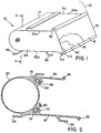
- FIG. 1 an air bag module 10 constructed according to one embodiment of the present invention is shown mounted in the instrument panel 12 of an automotive vehicle.
- the module 10 includes a reaction canister 14 which houses a folded air bag 16.
- a cover 18 for the air bag 16 is provided to prevent extraneous material from falling thereon and also into the reaction canister 14. The manner of attaching the cover forms no part of the present invention and, therefore, will not further be described herein.
- Integrally formed with the reaction canister 14 is an elongated continuous circumference one piece diffuser tube 20.
- Axially spaced inflating gas exit ports or slots 22 are provided in the portion of the wall of the diffuser tube 20 that faces the air bag 16.
- an inflator 24 Positioned within the diffuser tube 20 and rigidly held in a selected angular relation thereto, as further described hereinafter, is an inflator 24.
- Brackets 26 and 28 which are attached to the exterior of the reaction canister 14 are provided for facilitating the installation of the module 10 in the instrument panel 12.
- a decorative cover (not shown) which matches the profile of the surface of the instrument panel may be provided. When the module 10 is installed, such decorative cover forms part of the surface of the instrument panel.
- the reaction canister 14 includes a top panel 30 and a bottom panel 32, each of which have a respective first edge 30a, 32a and a respective second edge 30b, 32b.
- the top panel 30 and bottom panel 32 in conjunction with the diffuser tube 20, a first end plate 34, and a second end plate 36 define a cavity 38.
- the air bag 16, folded in a conventional manner, is housed in cavity 38.
- the cover 18 has been partially broken away to reveal the folded air bag therein.
- FIG. 2 shows a sectional view of the continuous circumference one piece diffuser tube 20 with the integrally formed top panel 30 and bottom panel 32 of the reaction canister 14.
- the diffuser 20 and the top panel 30 and the bottom panel 32 are formed as a continuous or unitary structure.
- this configuration can be produced in extruded aluminum.
- the slots 22 in the diffuser half of the diffuser tube 20, that half which faces the air bag 16 and the top panel 30 and the bottom panel 32, are located and sized so as to provide a desired distribution of gas generated by the inflator 24 into the air bag 16.
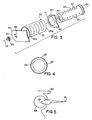
- the inflator 24 has an elongated cylindrical configuration, as shown in FIG. 3, and is retained in the diffuser tube 20, in concentric relation therewith, between the end plates 34 and 36.
- a circular opening 40 is provided in a first end 41 of the second end plate 36 and a smaller opening 42 with a key slot therein is provided in a first end 43 of the first end plate 34. Also, as shown, a flange 44 is provided on a first end of the inflator 24 and a threaded keyed stud 46 is provided on the second end thereof.
- the size of the opening 40 in the second end plate 36 is such as to allow the inflator 24 to be inserted in a snug fit with the second of the inflator 24, that having the stud 46 thereon, being passed therethrough.
- the size of the keyed opening 42 in the first end plate 34 is such as to snugly receive the stud 46.
- the arrangement is such that the relative angular positions of the inflator 24 and the diffuser tube 20 about the common longitudinal axis 48 thereof is determined by the keyed opening 42 in the first end plate 34 and the keyed inflator stud 46.
- a nut 50 on the stud 46 serves to hold the end plates 34 and 36 against first and second ends 20c and 20d, respectively, of the diffuser tube 20 with the inflator 24 captured therein.
- the second end 51 of the end plate 36 and the second end 53 of the end plate 34 are fixedly attached to the first and second edges, respectively, of the top panel 30 and the bottom panel 32 by drive screws 52 and 54. Screws 52 and 54 are screwed into grooves 56 and 58 that are provided at the respectively associated forwardly located edges of the top panel 30 and bottom panel 32.
- the internal components of the inflator 24 forms no part of this aspect of the present invention and may be any of the number of known constructions that are available commercially.
- such internal components may comprise that disclosed in U.S. Patent No. 4,890,860 granted to F.E. Schneiter on January 2, 1990 and assigned to the assignee of the present invention.
- FIG. 3 several longitudinal rows of axially spaced openings or exhaust ports 60 are provided on one side of inflator 24 parallel to the longitudinal axis 48 thereof and several substantially identical longitudinal rows of axially spaced exhaust ports 62 are provided on the other side thereof.
- the keying of the opening 42 in the first end plate 30 and of the inflator stud 46 is such as to cause the inflator rows of exhaust ports 60 and 62 to be selectively displaced angularly with respect to the diffuser slots 22 in the diffuser tube 20. This, as illustrated in FIG. 4, enables biasing of the jet flow of gases issuing from the slots 22. Selection of the degree of bias may readily be accomplished by appropriately angularly positioning, as by stamping, for example, of the keyed slot 42 in the first end plate 34 relatively to the keyed stud 46 on the end of the inflator 24.
- a pair of elongated key hole shaped slots or grooves 68 and 70 which are provided at the forward end of the cavity 38 in association, respectively, with the top panel 30 and the bottom panel 32.
- the fabric is formed and sewn into a loop, specifically a loop 64 at the upper side and a loop 66 at the lower side, as shown in FIG. 2.
- Each of the loops 64 and 66 is inserted in a respectively associated elongated groove 68 and 70 that are formed at the forward ends of the upper and lower panels 30 and 32, respectively.
- Squeezing of the loops 64 and 66 is required to facilitate such insertion through a narrow entry way provided into each of the grooves 68 and 70.
- Retention of the loops 64 and 66 in the grooves 68 and 70, and thereby attachment of the air bag 16 to the reaction canister 14 and diffuser tube 20, is effected by the insertion of rods 72 and 74 through the loops 64 and 66, respectively, and thereby through the respectively associated grooves 68 and 70.
- the rods 72 and 74 may be fastened securely in fully inserted position in any suitable manner.
- a reaction canister including a diffuser tube integral therewith for housing and positioning an inflator and an inflatable bag and for directing an inflating gas jet produced by the inflator for inflating the bag.
- the diffuser is a continuous circumference one piece diffuser.
- FIGS. 6 - 8 illustrate another aspect of the invention.
- These figures illustrate an extruded reaction canister or, more briefly, can body part, generally designated by the reference numeral 100, which includes the general form of a long, narrow, open receptacle or trough.
- the reaction canister body part 100 is shown separately in FIG. 6 and as a part of an air bag module assembly, generally designated by the reference numeral 105, in FIGS. 7 and 8.
- the reaction canister body part 100 includes an integrally shaped inflator chamber 106 having an exterior surface 107 and an interior surface 108 and, like inflator chambers that are commonly included in inflators designed and used in air bag module assemblies, can serve to house a gas generant material, such as commonly associated with pyrotechnic inflators, such as a gas generant pack 109, as shown in FIG. 7.
- a gas generant material such as commonly associated with pyrotechnic inflators, such as a gas generant pack 109, as shown in FIG. 7.
- inflator chamber in the form of a tube having a circular cross section will generally be preferred as such a structure is generally best suited for use in such applications wherein the chamber must withstand such pressure operation. It is to be understood, however, that in the practice of the invention, if desired, other shapes or forms of inflator chamber can be used.
- the internal components of the inflator chamber 106 and the composition and form of the gas generant material housed therein form no part of the present invention and may be any of a number of known constructions/formulations such as are commercially available. As discussed above and by way of example and not limitation, such internal components may comprise that disclosed in commonly assigned U.S. Patent No. 4,890,860 granted to F. E. Schneiter on January 2, 1990.
- the reaction canister body part 100 includes first and second opposite side walls or panels, e.g., a top side wall and a bottom side wall, 110 and 112, respectively, and first and second opposite ends, 114 and 115, respectively.
- the side walls can, for example, be formed directly continuous with the integrally shaped inflator chamber 106 or, as shown, continuously formed therewith via side wall connecting portions 116 and 118, respectively.
- the side walls 110 and 112, respectively, can generally be spaced apart so as to form an air bag retaining cavity, generally designated by the reference numeral 120, therebetween.
- the spaced apart side walls are generally parallel to each other, ensuring a more uniformly shaped air bag retaining cavity and thereby reducing the possibility of the air bag housed within the cavity therebetween undesirably getting caught or snagged such as by a protruding surface or edge of the reaction canister body part.
- the side walls can be otherwise angularly positioned relative to one another as may be desired in specific applications, such as to permit the accommodation of the reaction canister into a specifically shaped dash board or instrument panel opening.
- the side walls 110 and 112 are shown as being of different lengths, with the bottom side wall 112 being of a longer length than the top side wall 110.
- reaction canisters so shaped can more conveniently be incorporated within the dash board/instrument panel of most common automotive vehicles. It is to be understood, however, that the invention is not limited to use in conjunction with reaction canister side walls of such relative length. That is, the invention can similarly be used in conjunction with reaction canister body parts having side walls of similar lengths as well as reaction canister body parts wherein the length of the top side wall exceeds that of the bottom side wall.
- the inflator chamber 106 includes gas exit vents or ports 126 along a side 130 thereof. Such gas exit vents permit the gas generated within the inflation chamber to exit from the chamber and be directed for inflation of an air bag 134, as can more easily be seen by reference to FIGS. 7 and 8.
- one or more flow directing devices can be incorporated within the reaction canister assembly.
- flow directing devices can take the shape or form of baffles or gas port passages of particular size, shape and/or arrangement.
- such flow directing devices can take the form of and/or include an air bag retainer/diffuser device 140, as shown in FIGS. 7 and 8.
- the air bag retainer/diffuser device 140 includes a plurality of openings 141 therein to permit the passage of gas therethrough.
- the openings 141 are located and sized so as to provide a desired distribution of gas into the air bag 134.
- a preferred such device or system for use in the practice of the invention is a retainer device/system such as described in commonly assigned U.S. Patent Application 07/993,280, filed on December 18, 1992, and which device/system incorporates diffuser face member features such as described in commonly assigned U.S. Patent Application 07/993,277, also filed on December 18, 1992, the text of which applications are fully incorporated herein by reference.
- the size, geometry, and arrangement of the gas passage openings can be appropriately designed to satisfy specific application needs and the invention is not necessarily limited to use with a diffuser with gas passage openings of any specific configuration.
- such a diffuser device/system in addition to fostering desired gas diffusion can also assist in: 1) facilitating module assembly; 2) maintaining proper air bag retention within the assembly, and 3) maintaining desired separation of the hot inflator surfaces from both the surface of the air bag as well as from contact by the vehicle occupants.
- a means of retaining an air bag can advantageously avoid or minimize the need for conventional fastener devices such as screws or rivets, for example.
- a diffuser device/system such as the diffuser 140, can serve to facilitate control of bell mouthing of the reaction canister, thereby assisting in maintaining the integrity of the reaction canister.
- the reaction canister body part 100 includes, as a part of the side walls 110 and 112, integrally formed attachment sleeves 142.
- attachment sleeves allow for the fastenerless attachment of an air bag within an inflatable safety system.
- an alternative form of air bag retention/diffuser attachment preparation can be used, such as those that include fastener devices such as screws or rivets, such as described in the above-referenced U.S. patent application 07/993,277, for example.
- the invention can be practiced via the utilization of a cushion retainer, such as disclosed in the above-referenced U.S. Patent Application 07/993,280, which device serves to retain an air bag (e.g., a cushion) within the assembly while minimizing or, preferably, avoiding the use of fasteners such as screws or rivets, but which in this case does not necessarily incorporate diffuser features therein.
- a cushion retainer such as disclosed in the above-referenced U.S. Patent Application 07/993,280, which device serves to retain an air bag (e.g., a cushion) within the assembly while minimizing or, preferably, avoiding the use of fasteners such as screws or rivets, but which in this case does not necessarily incorporate diffuser features therein.
- the invention can be practiced both without the utilization of the referenced diffuser features and while making use of common forms of air bag attachment, such as the use of fasteners such as screws and/or rivets, for example.
- air bags in inflatable restraint systems can include one or more vent holes (not shown) therein whereby gases, such as produced via a gas generant material such as housed within the inflator chamber 106, can desirably be vented out of the air bag.
- gases such as produced via a gas generant material such as housed within the inflator chamber 106
- Such air bag vent holes can advantageously assist in post deployment venting of the air bag both immediately after a crash event (e.g., as may be desired to soften the bag upon contact by a vehicle occupant thereby resulting in a greater cushioning effect and to reduce the likelihood or extent of rebound by such vehicle occupant upon such contact) and subsequent thereto (e.g., such as may be desired to facilitate the exiting from the vehicle by the occupant subsequent to the deployment event).
- the air bag 134 has a thickened peripheral edge 143.
- Such thickening of an air bag is described in the above-referenced U.S. patent applications, i.e., 07/993,277 and 07/993,280, and can take the form, as shown, of a hemmed loop 144 of air bag material at the gas inlet opening edge of the air bag into which a selected bead material 145 is placed to better ensure positive engagement of the air bag 134 into the assembly 105.
- the air bag retainer/diffuser device 140 includes a channel 146 thereabout into which channel the thickened peripheral edge of the air bag can be inserted so as to be in cooperative relation with said attachment sleeve preparation and thus secured to form an air bag/diffuser subassembly for joinder to the reaction canister body part, as shown and as described in detail in the above-referenced patent applications.
- the bead material can suitably be fabricated from a wide range of materials such as metal or, preferably, plastic, especially an extruded thermoplastic and can take various shapes or forms to meet the needs of particular applications.
- the illustrated reaction canister body part 100 further includes canister vent holes 149 about the side wall connecting portions 116 and 118, respectively (see FIG. 8).
- canister vent holes allow for "behind the bag venting", whereby gas is vented from the canister in a rearward fashion thereby minimizing the likelihood of contact between the vented gas and the vehicle occupant.
- canister vent holes permit a leveling off the breakout pressure, e.g., the pressure at which an air bag initially being deployed breaks out through the cover layer of the assembly, such as from the air bag retaining cavity and into the interior of the vehicle, for example.
- the reaction canister body part 100 forms gas cooling cavities 150 wherein vented gases can suitably be cooled.
- a thermal conductive material 151 can be placed within the cooling cavities 150 to assist in the cooling of, e.g., removal of heat from, the gases vented out from the air bag.
- a thermal conductive material preferably has a large surface and is capable of absorbing large amounts of heat while permitting the vented gas to be passed therethrough.
- the so positioned thermal conductive material thus functions to assist in retaining generated or resulting heat within the confines of the reaction canister and thus away from the vehicle occupant.
- such a thermal conductive material can take the form of a metallic wool such as steel wool or, more preferably, due to the relatively greater heat conducting ability and lighter weight of aluminum, an aluminum wool.
- the body part further includes protective cover retaining preparations 152, shown as taking the form of slots about the outer extremity of each of the side walls 110 and 112, respectively.
- a protective cover 154 such as of fiber reinforced paper, for example, can be included as a part of the air bag module assembly 105 in the form of a wrap joined to the reaction canister body part 100 about the air bag 134 within the air bag retaining cavity 120 of the assembly.
- Such a protective cover 154 can be secured to the reaction canister body part 100 such as with an elastic band or other selected bead material 158 placed about the outer edge 160 of the protective cover 154, with the bead material secured within such a protective cover retainer slot preparation 152.
- Such a protective cover serves to help protect the air bag from damage such as by accidental or other undesired contact such as by or with other elements of the inflatable restraint system as well as extraneous elements in the environment to which the air bag can be exposed. Also, such a protective cover serves to desirably keep debris out of the reaction canister assembly.
- such a protective cover is preferably fabricated of a tough, wear resistant material which, while normally tear resistant, can be preferably broken or ruptured at predetermined or selected sites such as through the aid of perforations therein.
- a protective cover can be fabricated of fiber reinforced paper, such as that sold by E.I. Du Pont de Nemours Co. under the name TYVEK. It is to be understood, however, that other appropriate materials such as having such described or preferred properties or characteristics can also be used.
- the reaction canister body part 100 includes a plurality of end closure attachment preparations 164.
- Such attachment preparations can take the form of a hollow or, as the body part is preferably prepared by extrusion fabrication, such attachment preparations can preferably take the form of a groove or what is commonly referred to in the extrusion field as a "screw slot.” It is to be understood, however, that the attachment preparations and the form of attachment are not limited to the use of screw fasteners.
- attachment preparations 164 are preferably spaced about the periphery of the body part 100, both along the side walls 110 and 112, and about the inflator chamber 106, preferably about the exterior surface 107 thereof, so as to ensure secure attachment of end closures 170 (see FIG. 7) to the reaction canister body part 100 and preferably at least at each of the opposite ends 114 and 115 thereof.
- the end closures 170 retain the cross sectional shape of the reaction canister body part 100.
- the end closures can take the form of end plates such as with an integral inflator chamber base or, as may be preferred and as is shown in FIG. 7, a combination of end plates 174 (individually designated as 174A and 174B, respectively) and end bases 178 (individually designated as 178A and 178B, respectively).
- fasteners 180 such as swaging screw fasteners, such as made of appropriately hardened steel and which permits use in such pressure applications, can be used in securing such end closures in the assembly. Further, in one preferred embodiment of the invention and as illustrated in FIGS.
- the fasteners denominated 180A are used in simultaneously securing both end plates and end bases, while the fasteners denominated 180B are used to secure end plates and not end bases.
- the end plates 174 primarily serve to enclose the ends of the air bag retaining cavity formed by the reaction canister body part 100
- the end bases 178 primarily serve to enclose the ends of the integral inflator chamber 106 formed in the reaction canister body part 100 of the invention.
- the end bases 178 include a mating face 181 which upon assembly mates with the integral inflator chamber 106. That is, the mating face 181 properly receives one of the ends of the integrally shaped inflator chamber 106 to provide closure to the chamber 106.
- end bases comprising thicker and/or stronger materials than used in the end plates will typically be preferred as the end closures at the inflator chamber will typically be subjected to significantly greater pressures than the end closures of the air bag retaining cavity.
- the attachment preparations used for securing such end bases to the assembly typically must be able to withstand such significantly greater pressures.
- the end closure attachment preparations for use in attaching such end bases to the reaction canister body part e.g., the end closure attachment preparations designated 164A and generally in the form of four screw slots relatively equally spaced about the exterior surface 107 of the inflator chamber 106, and the fasteners used in combination therewith, i.e., the fasteners 180A, are of both a larger diameter and the fasteners are of a greater length than the end closure attachment preparations and fasteners, i.e., the preparations 164B and the fasteners 180B, that are used solely in securing end plates 174 to the reaction canister body part 100.
- Such a system and method of end closure attachment provides a relatively inexpensive, yet secure system and method for attaching end closures within the assembly to the reaction canister body part of the invention.
- the reaction canister body part 100 can also include one or more mounting portions, generally designated by the reference numeral 184.
- Such mounting portions can be either of an external type, i.e., for mounting of the reaction canister body part within a selected vehicle, or an internal or semi-internal type, i.e., for mounting of items to or within the reaction canister body part.
- an external mounting portion such as the mounting bracket 184A, can be appropriately positioned, orientated, shaped, and sized as desired to effect the desired result.
- an internal or semi-internal type mounting portion such as the mounting bracket 184B
- a mounting bracket 184B can, for example, be used in the formation of a shielded cavity or recess 190 useful in distancing and shielding the air bag from fastening nuts or other elements (not shown) used in the reaction canister assembly.
- the body part 100 is preferably fabricated by a continuous extrusion of an extrudable material, such as magnesium or, preferably, aluminum; which material is able to withstand the high temperatures and pressures to which such body part would typically be subjected to in such inflatable restraint system applications.
- extrusion fabrication of the body part permits and facilitates the incorporation into the design thereof, as needed or desired, of various design features and/or characteristics.
- such design features/characteristics can, for example, include as desired or needed one or more of the following: diffuser and/or air bag retainer attachment preparations, vent holes to facilitate desired gas venting, cooling cavities to permit desired gas cooling, protective cover retaining preparations to facilitate the retaining of a protective cover about the assembly, end closure attachment preparations whereby the attachment of end closures such as end plates or end plate/end base combinations to the reaction canister body part can be simplified, and mounting portions (both external, e.g., for mounting of the reaction canister body part within a selected vehicle, and internal or semi-internal, e.g., for mounting of items to or within the reaction canister body part).
- extrusion fabrication of the body part permits the rapid fabrication of the body with the added advantage that the extrusion can be cut to varying lengths to permit incorporation thereof in variously sized assemblies.
- end closures e.g., end plates and/or end plates with end bases, assist in maintaining the shape of the body part 100.
- end closures may be made of the same material as the reaction canister body part, e.g., aluminum, and can be stamped, machined, formed or extruded, as desired.
- reaction canister In order to counteract the forces, described above, to which a reaction canister will typically be subjected to during air bag deployment and which forces can result in undesired bell mouthing of the reaction canister, which in turn can result in damage to the surrounding instrument panel structure or components, it is generally desirable that the reaction canister be relatively rigid.
- a reaction canister body part incorporating one or more of the features described above will have increase rigidity as a result of the shape and forms added to effect the incorporation of the features therein.
- the reaction canister body part of the invention will preferably be formed from one material and it will be preferred that the wall forming the inflator chamber will be thicker than the balance of the wall portions of the part, i.e., the thickness of the wall 192 will exceed the thickness of the top side wall 110 and the bottom side wall 112.
- Such thicker wall portions are better suited to contain the relatively high gas generant pressures, e.g., 1500-3000 psi, such as would be expected to be produced therein with common pyrotechnic gas generant materials.
- the swaging screw is a form of fastener that has been found to have particular utility in the practice of the invention.
- Swaging screw fasteners generally form or swage a thread into a fastener hole or other attachment preparation upon insertion. (The swaging process produces a removal torque in excess of 80% of the screw setting torque.)
- Such thread formation generally occurs as a result of a stretching or a displacement of the material, typically metal, into which it is inserted, as opposed to a general removal of such material as commonly occurs when using a conventional thread cutting screw fastener.
- the fasteners are for use in conjunction with component parts of a vehicular inflatable restraining system
- the use of a thread cutting screw fastener can result in the formation of fine metal filings which are undesirable and not easily removed.
- metal filings are generally not created with swaging screw fasteners.
- the use of swaging screw fasteners allows the attachment preparations in the reaction canister body part of the invention to be formed by simple extrusion during the manufacture process, with the swaging screw fastener forming the threading during insertion.
- fasteners such as rivets, bolts, or other screw fasteners, for example, can, if desired, be used in the practice of the invention.
- reaction canister body part having an integral inflator chamber also both simplifies the manufacture and assembly of corresponding inflatable restraint modules and assures greater safety in operation as the disposition of the gas exit vents or ports in the inflator chamber is fixed relative to the reaction canister.
- time and effort normally required in assembly to ensure that the gas exit vents are properly orientated, as well as the likelihood of incorrect orientation, such as due to misalignment of the gas exit vents are virtually eliminated.
Landscapes
- Engineering & Computer Science (AREA)
- Mechanical Engineering (AREA)
- Physics & Mathematics (AREA)
- Fluid Mechanics (AREA)
- Air Bags (AREA)
Applications Claiming Priority (4)
| Application Number | Priority Date | Filing Date | Title |
|---|---|---|---|
| US46692 | 1993-04-12 | ||
| US08/046,692 US5407227A (en) | 1992-02-24 | 1993-04-12 | Inflatable restraint system reaction canister with integral inflator chamber |
| US43960 | 1993-04-13 | ||
| US08/043,960 US5407226A (en) | 1992-02-24 | 1993-04-13 | Inflatable restraint system reaction canister |
Publications (2)
| Publication Number | Publication Date |
|---|---|
| EP0620139A1 true EP0620139A1 (de) | 1994-10-19 |
| EP0620139B1 EP0620139B1 (de) | 1999-11-17 |
Family
ID=26721027
Family Applications (2)
| Application Number | Title | Priority Date | Filing Date |
|---|---|---|---|
| EP94302029A Expired - Lifetime EP0620140B2 (de) | 1993-04-12 | 1994-03-22 | Reaktionsgehäuse eines aufblasbaren Rückhaltesystems |
| EP19940302028 Expired - Lifetime EP0620139B1 (de) | 1993-04-12 | 1994-03-22 | Reaktionsgehäuse eines aufblasbaren Rückhaltesystems mit integriertem Ausblasvorrichtungsraum |
Family Applications Before (1)
| Application Number | Title | Priority Date | Filing Date |
|---|---|---|---|
| EP94302029A Expired - Lifetime EP0620140B2 (de) | 1993-04-12 | 1994-03-22 | Reaktionsgehäuse eines aufblasbaren Rückhaltesystems |
Country Status (3)
| Country | Link |
|---|---|
| EP (2) | EP0620140B2 (de) |
| DE (2) | DE69421638T2 (de) |
| ES (1) | ES2141798T3 (de) |
Cited By (16)
| Publication number | Priority date | Publication date | Assignee | Title |
|---|---|---|---|---|
| WO1995015871A1 (en) * | 1993-12-06 | 1995-06-15 | Alliedsignal, Inc. | Driver side air bag module with extruded housing |
| EP0672560A2 (de) * | 1994-03-14 | 1995-09-20 | Morton International, Inc. | Gaserzeugende Körper und kombinierte Reaktionsgehäuse und Aufblasvorrichtung |
| GB2289029A (en) * | 1994-05-04 | 1995-11-08 | Breed Automotive Tech | Two stage inflator with module venting for passenger side airbags |
| DE19602471A1 (de) * | 1995-01-24 | 1996-07-25 | Trw Vehicle Safety Systems | Airbagmodul |
| WO1996025309A1 (de) * | 1995-02-17 | 1996-08-22 | Petri Ag | Airbagmodul |
| EP0748723A1 (de) * | 1995-06-15 | 1996-12-18 | Morton International, Inc. | Mit Knautschzone versehene Seitenwand eines Airbagmoduls |
| EP0758599A1 (de) * | 1995-08-10 | 1997-02-19 | Morton International, Inc. | Überdruckableitung für Reaktionsbehältereinheit |
| EP0761506A2 (de) * | 1995-09-05 | 1997-03-12 | TRW Occupant Restraint Systems GmbH | Gassack-Rückhaltemodul |
| EP0787628A2 (de) * | 1995-09-23 | 1997-08-06 | VAW Aluminium AG | Airbagmodul-Profil |
| EP0794091A1 (de) * | 1996-03-08 | 1997-09-10 | TRW Occupant Restraint Systems GmbH | Gassack-Rückhaltemodul |
| EP0803409A2 (de) * | 1996-04-27 | 1997-10-29 | MST Automotive GmbH Automobil-Sicherheitstechnik | Beifahrer-Airbag-Modul |
| WO1998016410A1 (en) * | 1996-10-16 | 1998-04-23 | Breed Automotive Technology, Inc. | Air bag module with deployment flap |
| EP0769426A3 (de) * | 1995-10-19 | 1999-12-15 | MST Automotive GmbH Automobil-Sicherheitstechnik | Airbag-Gehäuse |
| EP1022196A3 (de) * | 1995-09-05 | 2000-10-11 | TRW Occupant Restraint Systems GmbH & Co. KG | Gassack-Rückhaltemodul |
| US6371509B1 (en) * | 1998-09-30 | 2002-04-16 | Trw Occupant Restraint Systems Gmbh & Co. Kg | Gas bag for a vehicle occupant restraint system |
| WO2006050718A1 (de) * | 2004-11-15 | 2006-05-18 | Takata-Petri Ag | Airbagmodul zum einbau in ein kraftfahrzeug |
Families Citing this family (15)
| Publication number | Priority date | Publication date | Assignee | Title |
|---|---|---|---|---|
| US5967551A (en) * | 1992-12-18 | 1999-10-19 | Autoliv Asp, Inc. | Reduced airbag deployment skewness with non-symmetric gas output inflators |
| DE4340855C2 (de) * | 1993-12-01 | 1996-05-09 | Opel Adam Ag | Befestigung eines Luftsackes im Gehäuse eines Airbagmoduls |
| US5435595A (en) * | 1994-01-14 | 1995-07-25 | Morton International, Inc. | Passenger side airbag module having lengthened reaction canister |
| EP0677433A1 (de) * | 1994-04-15 | 1995-10-18 | Morton International, Inc. | Luftsackmodul und Diffusor dafür |
| US5431433A (en) * | 1994-05-02 | 1995-07-11 | Morton International, Inc. | Fastenerless tethered deployment door for passenger-side airbag module |
| US5454588A (en) * | 1994-08-12 | 1995-10-03 | Morton International, Inc. | Inflatable cushion assembly |
| DE4442202C2 (de) * | 1994-11-17 | 1998-10-15 | Petri Ag | Beifahrer-Airbag-Modul |
| US5639111A (en) * | 1995-03-29 | 1997-06-17 | General Motors Corporation | Air bag module |
| US5570905A (en) * | 1995-03-28 | 1996-11-05 | Morton International, Inc. | Airbag tether attachment |
| EP0742124A1 (de) * | 1995-05-09 | 1996-11-13 | Morton International, Inc. | Wartungsfähiger Niet für ein Beifahrergaskissen-Modul |
| US5611562A (en) * | 1995-11-02 | 1997-03-18 | Trw Vehicle Safety Systems Inc. | Inflatable restraint module with inflator clamping reaction canister |
| DE202005010864U1 (de) | 2004-11-15 | 2005-09-22 | Takata-Petri Ag | Airbagmodul zum Einbau in ein Kraftfahrzeug |
| DE202005016457U1 (de) | 2005-10-17 | 2006-01-19 | Takata-Petri Ag | Airbagmodul für ein Kraftfahrzeug |
| WO2015067367A1 (de) * | 2013-11-08 | 2015-05-14 | Trw Automotive Gmbh | Gassack-modul |
| US11572030B1 (en) * | 2021-09-08 | 2023-02-07 | Autoliv Asp, Inc. | Airbag inflator assembly |
Citations (4)
| Publication number | Priority date | Publication date | Assignee | Title |
|---|---|---|---|---|
| US4941678A (en) * | 1989-06-29 | 1990-07-17 | Morton Thiokol, Inc. | Lightweight reaction can for passenger inflators |
| EP0496267A1 (de) * | 1991-01-19 | 1992-07-29 | Dynamit Nobel Aktiengesellschaft | Gasgenerator, insbesondere für Airbag |
| EP0529304A1 (de) * | 1991-08-20 | 1993-03-03 | Trw Repa Gmbh | Gassack-Rückhaltesystem-Baugruppe |
| EP0558240A1 (de) * | 1992-02-24 | 1993-09-01 | Morton International, Inc. | Reaktionsdose mit kreisförmigem Diffusor |
Family Cites Families (4)
| Publication number | Priority date | Publication date | Assignee | Title |
|---|---|---|---|---|
| DE2143166A1 (de) † | 1971-08-28 | 1973-03-08 | Heckler & Koch Gmbh | Passive sicherheitseinrichtung vom air-bag-typ fuer transportmittel |
| US3778085A (en) † | 1971-10-06 | 1973-12-11 | M Lipkin | Concealed pneumatic safety system |
| US5087071A (en) † | 1990-08-01 | 1992-02-11 | Trw Vehicle Safety Systems Inc. | Vehicle air bag structure and method of forming |
| US5263739A (en) * | 1992-12-28 | 1993-11-23 | General Motors Corporation | Air bag module |
-
1994
- 1994-03-22 EP EP94302029A patent/EP0620140B2/de not_active Expired - Lifetime
- 1994-03-22 DE DE1994621638 patent/DE69421638T2/de not_active Expired - Fee Related
- 1994-03-22 EP EP19940302028 patent/EP0620139B1/de not_active Expired - Lifetime
- 1994-03-22 DE DE1994610870 patent/DE69410870T3/de not_active Expired - Fee Related
- 1994-03-22 ES ES94302028T patent/ES2141798T3/es not_active Expired - Lifetime
Patent Citations (4)
| Publication number | Priority date | Publication date | Assignee | Title |
|---|---|---|---|---|
| US4941678A (en) * | 1989-06-29 | 1990-07-17 | Morton Thiokol, Inc. | Lightweight reaction can for passenger inflators |
| EP0496267A1 (de) * | 1991-01-19 | 1992-07-29 | Dynamit Nobel Aktiengesellschaft | Gasgenerator, insbesondere für Airbag |
| EP0529304A1 (de) * | 1991-08-20 | 1993-03-03 | Trw Repa Gmbh | Gassack-Rückhaltesystem-Baugruppe |
| EP0558240A1 (de) * | 1992-02-24 | 1993-09-01 | Morton International, Inc. | Reaktionsdose mit kreisförmigem Diffusor |
Cited By (28)
| Publication number | Priority date | Publication date | Assignee | Title |
|---|---|---|---|---|
| WO1995015871A1 (en) * | 1993-12-06 | 1995-06-15 | Alliedsignal, Inc. | Driver side air bag module with extruded housing |
| EP0672560A2 (de) * | 1994-03-14 | 1995-09-20 | Morton International, Inc. | Gaserzeugende Körper und kombinierte Reaktionsgehäuse und Aufblasvorrichtung |
| EP0672560A3 (de) * | 1994-03-14 | 1995-11-22 | Morton Int Inc | Gaserzeugende Körper und kombinierte Reaktionsgehäuse und Aufblasvorrichtung. |
| GB2289029A (en) * | 1994-05-04 | 1995-11-08 | Breed Automotive Tech | Two stage inflator with module venting for passenger side airbags |
| DE19602471A1 (de) * | 1995-01-24 | 1996-07-25 | Trw Vehicle Safety Systems | Airbagmodul |
| US6109649A (en) * | 1995-02-17 | 2000-08-29 | Petri Ag, Niederlassung Berlin | Airbag module |
| WO1996025309A1 (de) * | 1995-02-17 | 1996-08-22 | Petri Ag | Airbagmodul |
| EP0748723A1 (de) * | 1995-06-15 | 1996-12-18 | Morton International, Inc. | Mit Knautschzone versehene Seitenwand eines Airbagmoduls |
| EP0758599A1 (de) * | 1995-08-10 | 1997-02-19 | Morton International, Inc. | Überdruckableitung für Reaktionsbehältereinheit |
| EP0761506A2 (de) * | 1995-09-05 | 1997-03-12 | TRW Occupant Restraint Systems GmbH | Gassack-Rückhaltemodul |
| EP0761506A3 (de) * | 1995-09-05 | 1997-08-06 | Trw Repa Gmbh | Gassack-Rückhaltemodul |
| EP1022196A3 (de) * | 1995-09-05 | 2000-10-11 | TRW Occupant Restraint Systems GmbH & Co. KG | Gassack-Rückhaltemodul |
| US5732971A (en) * | 1995-09-05 | 1998-03-31 | Trw Occupant Restraint Systems Gmbh | Gas bag restraint module |
| EP0787628A2 (de) * | 1995-09-23 | 1997-08-06 | VAW Aluminium AG | Airbagmodul-Profil |
| US5816607A (en) * | 1995-09-23 | 1998-10-06 | Vaw Aluminium Ag | Airbag system |
| EP0787628A3 (de) * | 1995-09-23 | 1998-06-10 | VAW Aluminium AG | Airbagmodul-Profil |
| EP0769426A3 (de) * | 1995-10-19 | 1999-12-15 | MST Automotive GmbH Automobil-Sicherheitstechnik | Airbag-Gehäuse |
| US5934700A (en) * | 1996-03-08 | 1999-08-10 | Trw Occupant Restraint Systems Gmbh | Gas bag restraint module |
| EP0794091A1 (de) * | 1996-03-08 | 1997-09-10 | TRW Occupant Restraint Systems GmbH | Gassack-Rückhaltemodul |
| EP0803409A3 (de) * | 1996-04-27 | 1999-01-13 | MST Automotive GmbH Automobil-Sicherheitstechnik | Beifahrer-Airbag-Modul |
| US5944340A (en) * | 1996-04-27 | 1999-08-31 | Mst Automotive Gmbh | Airbag module for passenger seat |
| EP0803409A2 (de) * | 1996-04-27 | 1997-10-29 | MST Automotive GmbH Automobil-Sicherheitstechnik | Beifahrer-Airbag-Modul |
| US5823566A (en) * | 1996-10-16 | 1998-10-20 | Alliedsignal Inc. | Air bag module with deployment flap |
| WO1998016410A1 (en) * | 1996-10-16 | 1998-04-23 | Breed Automotive Technology, Inc. | Air bag module with deployment flap |
| US6371509B1 (en) * | 1998-09-30 | 2002-04-16 | Trw Occupant Restraint Systems Gmbh & Co. Kg | Gas bag for a vehicle occupant restraint system |
| WO2006050718A1 (de) * | 2004-11-15 | 2006-05-18 | Takata-Petri Ag | Airbagmodul zum einbau in ein kraftfahrzeug |
| WO2006050719A1 (de) | 2004-11-15 | 2006-05-18 | Takata-Petri Ag | Modulbaugruppe für eine airbageinrichtung zum schutz von insassen eines kraftfahrzeugs |
| US7644949B2 (en) | 2004-11-15 | 2010-01-12 | Takata-Petri Ag | Airbag module assembly |
Also Published As
| Publication number | Publication date |
|---|---|
| EP0620140B1 (de) | 1998-06-10 |
| DE69410870T3 (de) | 2001-05-23 |
| EP0620140B2 (de) | 2001-01-24 |
| DE69421638D1 (de) | 1999-12-23 |
| DE69410870T2 (de) | 1999-01-14 |
| EP0620140A1 (de) | 1994-10-19 |
| DE69421638T2 (de) | 2000-06-15 |
| EP0620139B1 (de) | 1999-11-17 |
| DE69410870D1 (de) | 1998-07-16 |
| ES2141798T3 (es) | 2000-04-01 |
Similar Documents
| Publication | Publication Date | Title |
|---|---|---|
| US5407227A (en) | Inflatable restraint system reaction canister with integral inflator chamber | |
| EP0620139B1 (de) | Reaktionsgehäuse eines aufblasbaren Rückhaltesystems mit integriertem Ausblasvorrichtungsraum | |
| EP0558240B1 (de) | Reaktionsdose mit kreisförmigem Diffusor | |
| US5407226A (en) | Inflatable restraint system reaction canister | |
| US5470105A (en) | Diffuser device and incorporation thereof in an inflatable restraint system | |
| US4941678A (en) | Lightweight reaction can for passenger inflators | |
| US7195279B2 (en) | Gas flow deflection apparatus and method for airbag systems | |
| JPH08230596A (ja) | 同乗者用エアバック拘束装置 | |
| US5791680A (en) | Attachment of airbag module assembly protective cover | |
| US5967551A (en) | Reduced airbag deployment skewness with non-symmetric gas output inflators | |
| AU658782B2 (en) | Inflatable restraint system reaction canister with integral inflator chamber | |
| US5566975A (en) | Controlled pressure relief of an inflatable restraint reaction canister | |
| AU660120B2 (en) | Inflatable restraint system reaction canister | |
| EP0694446A2 (de) | Verminderte Luftsack-Entfaltungsverzerrung mit Unsymmetrischem Aufblasvorrichtungsgasaustritt | |
| US11572030B1 (en) | Airbag inflator assembly | |
| US5779265A (en) | Reaction canister with inflator output treatment fins | |
| EP0791512B1 (de) | Vorrichtung und Verfahren zur Gasflussregelung von einer Aufblasvorrichtung eines Gassacks | |
| CA2210009C (en) | Continuous circumference diffuser reaction canister |
Legal Events
| Date | Code | Title | Description |
|---|---|---|---|
| PUAI | Public reference made under article 153(3) epc to a published international application that has entered the european phase |
Free format text: ORIGINAL CODE: 0009012 |
|
| AK | Designated contracting states |
Kind code of ref document: A1 Designated state(s): BE DE ES FR GB IT NL SE |
|
| 17P | Request for examination filed |
Effective date: 19950313 |
|
| 17Q | First examination report despatched |
Effective date: 19970530 |
|
| GRAG | Despatch of communication of intention to grant |
Free format text: ORIGINAL CODE: EPIDOS AGRA |
|
| GRAG | Despatch of communication of intention to grant |
Free format text: ORIGINAL CODE: EPIDOS AGRA |
|
| GRAH | Despatch of communication of intention to grant a patent |
Free format text: ORIGINAL CODE: EPIDOS IGRA |
|
| GRAH | Despatch of communication of intention to grant a patent |
Free format text: ORIGINAL CODE: EPIDOS IGRA |
|
| RAP1 | Party data changed (applicant data changed or rights of an application transferred) |
Owner name: AUTOLIV ASP, INC. |
|
| GRAA | (expected) grant |
Free format text: ORIGINAL CODE: 0009210 |
|
| AK | Designated contracting states |
Kind code of ref document: B1 Designated state(s): BE DE ES FR GB IT NL SE |
|
| PG25 | Lapsed in a contracting state [announced via postgrant information from national office to epo] |
Ref country code: IT Free format text: LAPSE BECAUSE OF FAILURE TO SUBMIT A TRANSLATION OF THE DESCRIPTION OR TO PAY THE FEE WITHIN THE PRESCRIBED TIME-LIMIT;WARNING: LAPSES OF ITALIAN PATENTS WITH EFFECTIVE DATE BEFORE 2007 MAY HAVE OCCURRED AT ANY TIME BEFORE 2007. THE CORRECT EFFECTIVE DATE MAY BE DIFFERENT FROM THE ONE RECORDED. Effective date: 19991117 Ref country code: BE Free format text: LAPSE BECAUSE OF FAILURE TO SUBMIT A TRANSLATION OF THE DESCRIPTION OR TO PAY THE FEE WITHIN THE PRESCRIBED TIME-LIMIT Effective date: 19991117 |
|
| REF | Corresponds to: |
Ref document number: 69421638 Country of ref document: DE Date of ref document: 19991223 |
|
| ET | Fr: translation filed | ||
| REG | Reference to a national code |
Ref country code: ES Ref legal event code: FG2A Ref document number: 2141798 Country of ref document: ES Kind code of ref document: T3 |
|
| PLBE | No opposition filed within time limit |
Free format text: ORIGINAL CODE: 0009261 |
|
| STAA | Information on the status of an ep patent application or granted ep patent |
Free format text: STATUS: NO OPPOSITION FILED WITHIN TIME LIMIT |
|
| 26N | No opposition filed | ||
| REG | Reference to a national code |
Ref country code: GB Ref legal event code: IF02 |
|
| PGFP | Annual fee paid to national office [announced via postgrant information from national office to epo] |
Ref country code: NL Payment date: 20040229 Year of fee payment: 11 |
|
| PGFP | Annual fee paid to national office [announced via postgrant information from national office to epo] |
Ref country code: GB Payment date: 20040317 Year of fee payment: 11 |
|
| PGFP | Annual fee paid to national office [announced via postgrant information from national office to epo] |
Ref country code: SE Payment date: 20040319 Year of fee payment: 11 |
|
| PG25 | Lapsed in a contracting state [announced via postgrant information from national office to epo] |
Ref country code: GB Free format text: LAPSE BECAUSE OF NON-PAYMENT OF DUE FEES Effective date: 20050322 |
|
| PG25 | Lapsed in a contracting state [announced via postgrant information from national office to epo] |
Ref country code: SE Free format text: LAPSE BECAUSE OF NON-PAYMENT OF DUE FEES Effective date: 20050323 |
|
| PG25 | Lapsed in a contracting state [announced via postgrant information from national office to epo] |
Ref country code: NL Free format text: LAPSE BECAUSE OF NON-PAYMENT OF DUE FEES Effective date: 20051001 |
|
| EUG | Se: european patent has lapsed | ||
| GBPC | Gb: european patent ceased through non-payment of renewal fee |
Effective date: 20050322 |
|
| NLV4 | Nl: lapsed or anulled due to non-payment of the annual fee |
Effective date: 20051001 |
|
| PGFP | Annual fee paid to national office [announced via postgrant information from national office to epo] |
Ref country code: ES Payment date: 20090318 Year of fee payment: 16 |
|
| PGFP | Annual fee paid to national office [announced via postgrant information from national office to epo] |
Ref country code: DE Payment date: 20090127 Year of fee payment: 16 |
|
| PGFP | Annual fee paid to national office [announced via postgrant information from national office to epo] |
Ref country code: FR Payment date: 20090121 Year of fee payment: 16 |
|
| REG | Reference to a national code |
Ref country code: FR Ref legal event code: ST Effective date: 20101130 |
|
| PG25 | Lapsed in a contracting state [announced via postgrant information from national office to epo] |
Ref country code: FR Free format text: LAPSE BECAUSE OF NON-PAYMENT OF DUE FEES Effective date: 20100331 |
|
| PG25 | Lapsed in a contracting state [announced via postgrant information from national office to epo] |
Ref country code: DE Free format text: LAPSE BECAUSE OF NON-PAYMENT OF DUE FEES Effective date: 20101001 |
|
| REG | Reference to a national code |
Ref country code: ES Ref legal event code: FD2A Effective date: 20110418 |
|
| PG25 | Lapsed in a contracting state [announced via postgrant information from national office to epo] |
Ref country code: ES Free format text: LAPSE BECAUSE OF NON-PAYMENT OF DUE FEES Effective date: 20110404 |
|
| PG25 | Lapsed in a contracting state [announced via postgrant information from national office to epo] |
Ref country code: ES Free format text: LAPSE BECAUSE OF NON-PAYMENT OF DUE FEES Effective date: 20100323 |