EP0620076B1 - Verfahren und System zum Messen der Temperatur in einem Retort - Google Patents
Verfahren und System zum Messen der Temperatur in einem Retort Download PDFInfo
- Publication number
- EP0620076B1 EP0620076B1 EP94105484A EP94105484A EP0620076B1 EP 0620076 B1 EP0620076 B1 EP 0620076B1 EP 94105484 A EP94105484 A EP 94105484A EP 94105484 A EP94105484 A EP 94105484A EP 0620076 B1 EP0620076 B1 EP 0620076B1
- Authority
- EP
- European Patent Office
- Prior art keywords
- retort
- workpiece
- temperature
- diffusion bonding
- end portion
- Prior art date
- Legal status (The legal status is an assumption and is not a legal conclusion. Google has not performed a legal analysis and makes no representation as to the accuracy of the status listed.)
- Expired - Lifetime
Links
- 238000000034 method Methods 0.000 title claims description 53
- 238000009792 diffusion process Methods 0.000 claims description 48
- 239000002184 metal Substances 0.000 claims description 19
- 229910052751 metal Inorganic materials 0.000 claims description 19
- 239000000463 material Substances 0.000 claims description 13
- 238000010438 heat treatment Methods 0.000 claims description 4
- 238000005219 brazing Methods 0.000 claims description 2
- 238000007789 sealing Methods 0.000 claims 3
- 238000005259 measurement Methods 0.000 description 8
- 238000012544 monitoring process Methods 0.000 description 7
- 238000009529 body temperature measurement Methods 0.000 description 5
- 150000002739 metals Chemical class 0.000 description 5
- 229910045601 alloy Inorganic materials 0.000 description 3
- 239000000956 alloy Substances 0.000 description 3
- 238000013459 approach Methods 0.000 description 3
- IJGRMHOSHXDMSA-UHFFFAOYSA-N Atomic nitrogen Chemical compound N#N IJGRMHOSHXDMSA-UHFFFAOYSA-N 0.000 description 2
- RTAQQCXQSZGOHL-UHFFFAOYSA-N Titanium Chemical compound [Ti] RTAQQCXQSZGOHL-UHFFFAOYSA-N 0.000 description 2
- 238000007906 compression Methods 0.000 description 2
- 239000004020 conductor Substances 0.000 description 2
- 239000000356 contaminant Substances 0.000 description 2
- 238000011109 contamination Methods 0.000 description 2
- 230000003028 elevating effect Effects 0.000 description 2
- 239000007789 gas Substances 0.000 description 2
- 238000005304 joining Methods 0.000 description 2
- 230000002093 peripheral effect Effects 0.000 description 2
- 238000012545 processing Methods 0.000 description 2
- 239000010936 titanium Substances 0.000 description 2
- 229910052719 titanium Inorganic materials 0.000 description 2
- 229910021324 titanium aluminide Inorganic materials 0.000 description 2
- 229910001069 Ti alloy Inorganic materials 0.000 description 1
- OQPDWFJSZHWILH-UHFFFAOYSA-N [Al].[Al].[Al].[Ti] Chemical compound [Al].[Al].[Al].[Ti] OQPDWFJSZHWILH-UHFFFAOYSA-N 0.000 description 1
- QVGXLLKOCUKJST-UHFFFAOYSA-N atomic oxygen Chemical compound [O] QVGXLLKOCUKJST-UHFFFAOYSA-N 0.000 description 1
- 230000003749 cleanliness Effects 0.000 description 1
- 238000001816 cooling Methods 0.000 description 1
- 230000001419 dependent effect Effects 0.000 description 1
- 238000013461 design Methods 0.000 description 1
- 238000009826 distribution Methods 0.000 description 1
- 238000012625 in-situ measurement Methods 0.000 description 1
- 239000011261 inert gas Substances 0.000 description 1
- 238000003780 insertion Methods 0.000 description 1
- 230000037431 insertion Effects 0.000 description 1
- 238000004519 manufacturing process Methods 0.000 description 1
- 238000002844 melting Methods 0.000 description 1
- 230000008018 melting Effects 0.000 description 1
- 239000007769 metal material Substances 0.000 description 1
- 238000012806 monitoring device Methods 0.000 description 1
- 229910052757 nitrogen Inorganic materials 0.000 description 1
- 239000001301 oxygen Substances 0.000 description 1
- 229910052760 oxygen Inorganic materials 0.000 description 1
- 238000004886 process control Methods 0.000 description 1
- 230000001681 protective effect Effects 0.000 description 1
- 238000005086 pumping Methods 0.000 description 1
- 238000009877 rendering Methods 0.000 description 1
- 239000010935 stainless steel Substances 0.000 description 1
- 229910001220 stainless steel Inorganic materials 0.000 description 1
- 238000012546 transfer Methods 0.000 description 1
- 239000011800 void material Substances 0.000 description 1
- XLYOFNOQVPJJNP-UHFFFAOYSA-N water Chemical compound O XLYOFNOQVPJJNP-UHFFFAOYSA-N 0.000 description 1
- 238000003466 welding Methods 0.000 description 1
Images

Classifications
-
- B—PERFORMING OPERATIONS; TRANSPORTING
- B23—MACHINE TOOLS; METAL-WORKING NOT OTHERWISE PROVIDED FOR
- B23K—SOLDERING OR UNSOLDERING; WELDING; CLADDING OR PLATING BY SOLDERING OR WELDING; CUTTING BY APPLYING HEAT LOCALLY, e.g. FLAME CUTTING; WORKING BY LASER BEAM
- B23K20/00—Non-electric welding by applying impact or other pressure, with or without the application of heat, e.g. cladding or plating
- B23K20/02—Non-electric welding by applying impact or other pressure, with or without the application of heat, e.g. cladding or plating by means of a press ; Diffusion bonding
- B23K20/023—Thermo-compression bonding
-
- G—PHYSICS
- G01—MEASURING; TESTING
- G01K—MEASURING TEMPERATURE; MEASURING QUANTITY OF HEAT; THERMALLY-SENSITIVE ELEMENTS NOT OTHERWISE PROVIDED FOR
- G01K1/00—Details of thermometers not specially adapted for particular types of thermometer
- G01K1/14—Supports; Fastening devices; Arrangements for mounting thermometers in particular locations
Definitions
- the present invention generally relates to methods and systems for temperature measurement and control inside a container during a high temperature heating process, and more particularly to the measurement and control of temperatures within a sealed container or retort prior to and during diffusion bonding of a metallic sandwich structure.
- a well-known technique for joining metal is diffusion bonding. This process involves metallurgically joining surfaces of similar or dissimilar metals by applying heat and pressure for a time duration so as to cause co-mingling of atoms at the joint interface.
- the application of pressure accomplishes a plastic flow of the material to fill normal void areas. If the pressure is too low, small voids will remain at the joint interface and the joint strength will be less than the maximum attainable.
- the application of pressure also breaks up the surface oxides and surface asperites so as to press clean surfaces for bonding.
- the elevated temperatures used for diffusion bonding serve to accelerate diffusion of atoms at the joint interfaces as well as to provide a metal softening which aids in surface deformation thereby allowing more intimate contact for atom bonding and movement across the joint interface.
- the controlled environment has been attained through the use of a closed, sealed and evacuated metallic envelope known as a "retort".
- a retort typically, the retort is provided with external instrumentation for the purpose of monitoring the parameters of the diffusion bonding process.
- exact measurement inside the retort of the temperatures of the components necessary for successful and repeatable diffusion bonding is not attainable.
- first and second articles of metal are disposed within a flexible container that comprises telescoping elements.
- the interior of the flexible container communicates with a source of inert gas through a conduit.
- the temperature of the interior of the container is advantageously measured by a thermocouple which is connected by wires to external circuitry for display of the temperature.
- Another object of the present invention is to provide apparatus and a method for monitoring temperatures within a chamber heated to diffusion bonding temperatures without disturbing the chamber.
- Another object of the present invention is to provide temperature monitoring apparatus for placement at selected locations about a workpiece secured within diffusion bonding tooling without disturbing the tooling once the latter is set up.
- Yet another object of the invention is to provide an apparatus for making in-situ measurements of temperature within a sealed retort, without disrupting either the bonding process or the evacuated, controlled environment.
- Still another object is to provide a method of measuring thermal control parameters for a workpiece within a sealed retort via strategically located measurement devices in a diffusion bonding processing chamber whereby thermal processing control parameters for subsequent diffusion bonding processes can be established.
- the invention includes a metallic container or "retort" enveloping a workpiece prepared for diffusion bonding and temperature measuring apparatus including thermocouple devices strategically placed at locations on or about the workpiece.
- the retort comprises upper and lower metal sheets which are to be sealed at edges about the workpiece.
- Vacuum lines connected to the chamber formed between the upper and lower sheets within which the workpiece is contained, also carry leads from the thermocouple devices to temperature display and recording apparatus located outside the retort. Thereafter, the vacuum line entry points for the thermocouple leads are sealed to prevent ingress of contaminants into the retort during the diffusion bonding process.
- the temperatures on or about the workpiece are measured during the course of the diffusion bonding process, and the relationship between the time over which the temperature is elevated and the temperatures at the specified locations is determined. This relationship is then used in the current process, as well as in subsequent processes, to control both the external temperature to which the retort is subjected (for elevating the workpiece to the target temperature) and the time at which the specified temperature is to be applied.
- diffusion bonding is a process through which separate elements can be joined to form a single unitary mass.
- the quality of the bond and the parameters employed necessarily vary for each particular choice of material used.
- the present invention is particularly directed to reactive metals which have surfaces that would be contaminated at the elevated temperatures required for both diffusion bonding and superplastic pre-forming, i.e., at the temperatures of 1700° F to about 1900° F depending on the specific alloy used.
- the invention contemplates the application of diffusion bonding techniques to a stack of sheets of such reactive metals.
- the invention is especially suited for the monitoring and control of temperatures during diffusion bonding of a stack of sheets of titanium aluminide.
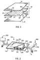
- Figure 1 shows a typical stacked arrangement 40 of sheets of metal which have been prepared, by application of stop-off material at predetermined locations, for diffusion bonding prior to being formed into a sandwich structure.
- the stacked arrangement 40 includes three sheets 10, 12, 14 each having upper principal surfaces 15, 17, and 19, and lower principal surfaces opposite the upper surfaces (not numbered).
- Various areas of the sheets see areas 30, 32, 34, 92 and 94) have been covered with stop-off material to prevent bonding at those locations.
- the number of sheets used to form the stack varies with loading conditions and design requirements; however, a minimum of two sheets must be used. At least one of the sheets must exhibit superplastic properties, and of greatest interest are materials that exhibit superplastic properties within a temperature range required for diffusion bonding and that are subject to contamination at forming temperatures, as for example titanium aluminides. It is important to note that the forming temperature for such materials can be as great as 1800° F.
- the initial thickness of metal blanks 10, 12, 14 is determined as a function of the dimensions of the part to be formed.
- the stack of metal sheets must be contained within an envelope or retort (as seen at 100 in Figure 2) in order to prevent contamination by the environment in which the process of diffusion bonding is to take place.
- the retort is formed from two thin sheets of metal, fabricated from a material such as stainless steel. The sheets are of the same size and are disposed in face to face relationship and secured (as by welding) to one another about the peripheral edges of the sheets.
- SPF superplastic forming
- the stop-off material applied to areas 92 and 94 prevent bonding of the sheets of the stack so that tubes used in the superplastic forming process can be inserted into the stack interior to permit introduction of cleansing gas or evacuation of the interior of the stack.
- superplastic forming of the diffusion bonded stack of sheets can take place within the retort before its removal.
- FIG. 2 shows the workpiece sealed within retort 100 which comprises upper and lower sheets 102, 104 of metal sealed to one another along their peripheral edges (shown at 110 in the Figure 2 representation).
- retort 100 which comprises upper and lower sheets 102, 104 of metal sealed to one another along their peripheral edges (shown at 110 in the Figure 2 representation).
- temperature monitoring devices are disposed at predetermined locations. These temperature monitoring instruments (discussed in more detail below) are used to measure the temperature which the stack edges have attained during the heating up process in advance of, and during, the gas pressure diffusion bonding process.
- the present invention provides a cure for that problem, by allowing placement of thermocouples at the stack edges and within the retort.
- thermocouples or similar temperature sensing devices 210, 212, 214 have been disposed at spaced locations along one edge of the stack, while a second set of thermocouples or similar temperature sensing devices 220, 222, 224 have been disposed at spaced locations along an opposite edge of the stack.
- thermocouples in Figure 2 are shown as having been placed on opposite sides of the stack, it is to be understood that the present invention embraces the placement of such temperature sensing devices all around the perimeter of the stack, or at whatever locations about the stack would most accurately reflect the temperature gradient or distribution within the various sheets of the stack. While the embodiment depicted in this application includes two sets of three thermocouples, any number of thermocouples or similar devices can be used.
- the wires connected to the first set of thermocouples 210, 212, 214 extend from the inside of the retort to a tube 230 at one end of the retort, while the wires associated with the second set of thermocouples extend from the thermocouples inside the retort to a tube 240 at the opposite end of the retort.
- the invention contemplates that the wires associated with both the first set and the second set of thermocouples could extend from the interior of the retort at the same single side thereof through the same tube (either tube 230 or tube 240).
- the configuration of the tube would allow for application of a vacuum through one retort end with a vacuum gage at the opposite end merely to measure and/or record the vacuum level.
- tubes 230 and 240 are provided primarily for the purpose of connecting the interior of the retort with apparatus for placing the retort interior under a vacuum, they also enable temperature monitoring of the interior volume of the retort while the retort volume is under vacuum conditions, as well as prior to, during, and following the diffusion bonding process.
- the tubes 230 and 240 are fabricated from a material which is strong enough to maintain their cylindrical configuration throughout the entire window of time during which a vacuum is impressed on the retort and then diffusion bonding pressures are applied to the retort. More particularly, the tube 230 communicates vacuum pump 250 with the retort interior volume from the retort one end (the left hand side in Figure 2), while the tube 240 communicates valving and metering apparatus 260 with the retort interior volume from the retort other end (the right hand side in Figure 2).
- Figure 3 is an enlarged view of a region of one of the tubes shown in the vicinity of the branched tube portions 232 and 234.
- Tube portion 232 is coupled with the vacuum equipment (the valving and metering apparatus 260) while tube portion 234 contains the thermocouple wires passing from within the retort to a point of connection with temperature measurement display apparatus (not shown) located outside of the retort.
- FIG 4 is a cross-sectional view of the tube portion carrying the thermocouple wires (note Figure 3) looking down into the tube portion from the end of the tube portion.
- thermocouple wires there are three thermocouple wires disposed within the tube, the three wires being substan- tially snuggly engaged with one another and with the internal cylindrical surface of the tube.
- Each wire includes at least one inner conductor, an outer sheathing and a tube surrounding the outer sheathing, with the outer sheathing being swaged about the inner conductor.
- thermocouples Since the temperature measurement system has become an integral part of the vacuum pumping system, it is necessary that the exit port of the thermocouples be leak tight.
- One method to achieve leak tightness is to flow an appropriate braze alloy between the sheaths of the thermocouples and the vacuum exit port tubing. If this method is used, the junction must be a sufficient distance from the heat source to prevent subsequent metal flow or melting.
- the apparatus thus described facilitates the measurement of temperature-related parameters for a workpiece disposed in a sealed retort located within a diffusion bonding chamber so that a set of thermal control parameters can be established for use in effecting subsequent diffusion bonding operations.
- This is accomplished by strategically locating temperature measurement devices in a diffusion bonding process chamber on or adjacent the edges of a workpiece within the retort. While measuring the temperatures on or about the workpiece during the process, the relationship between the time over which the temperature is elevated and the temperatures at the specified locations is determined. This relationship is then used in the current process, as well as in subsequent processes, to control both the external temperature to which the retort is subjected (for elevating the workpiece to the target temperature) and the time at which the specified temperature is to be applied.
- the apparatus and system, respectively, embraced by the invention includes a metallic container or "retort" enveloping a workpiece prepared for diffusion bonding and temperature measuring apparatus including thermocouple devices strategically placed at locations on or about the workpiece.
- the retort consists of upper and lower metal sheets sealable at edges about the workpiece.
- Vacuum conduits communicate the sealed retort chamber with display and recording apparatus located outside the retort. Leads from the thermocouple devices run through the vacuum conduits to the apparatus.
- the vacuum conduits for the thermocouple leads are sealed to prevent ingress of contaminants into the retort during the diffusion bonding process.
- the temperatures on or about the workpiece are measured during the course of the diffusion bonding process, and the relationship between the time over which the temperature is elevated and the temperatures at the specified locations is recorded. This relationship is then used, in the current process as well as in subsequent processes, to control both the external temperature to which the retort is subjected and the time at which the specified temperature is to be applied.
Landscapes
- Engineering & Computer Science (AREA)
- Mechanical Engineering (AREA)
- Physics & Mathematics (AREA)
- General Physics & Mathematics (AREA)
- Pressure Welding/Diffusion-Bonding (AREA)
- Measuring Temperature Or Quantity Of Heat (AREA)
Claims (9)
- Ein System zum Messen der Temperatur eines innerhalb einer Retorte (100) abgedichteten Werkstücks (40) vor und während der Diffusionsverbindung der Werkstückkomponenten, wobei folgendes vorgesehen ist:Temperaturmeßinstrumente (210, 212, 214), angeordnet benachbart zu Teilen des Werkstücks (40) innerhalb der Retorte (100),Verbindungsleitungen, welche die Instrumente (210, 212, 214) mit Anzeigevorrichtungen, angeordnet außerhalb der Retorte (100), verbinden,mit dem Innenraum der Retorte (100) und mit den Anzeigevorrichtungen gekoppelte Leitungen (230, 240), wobei jede der Leitungen zwei verzweigte Endteile aufweist, wobei ein erster Endteil (232) den Innenraum der Retorte (100) mit Vakuumerzeugungsmitteln (250) verbindet, und wobei ferner ein zweiter Endteil (234) mindestens eine Rohrregion aufweist, durch die die Verbindungsleitungen laufen zur Verbindung mit den Anzeigevorrichtungen, undMittel (236) zum Abdichten der ersten und zweiten Endteile, um einen evakuierten Zustand innerhalb der Retorte aufrecht zu erhalten, nachdem ein Vakuum daran angelegt ist.
- System nach Anspruch 1, wobei der erste verzweigte Endteil der mindestens einen Leitungen (240) eine zweite Rohrregion aufweist, und zwar in Verbindung stehend mit den Vakuumerzeugungsmitteln (250), wobei die ersten und zweiten Rohrregionen (232, 234) am gleichen Endteil der Leitung angeordnet sind.
- System nach Anspruch 1, wobei die Mittel zum Abdichten der ersten und zweiten Endteile jeder der Leitungen Hartlötmaterial (236) aufweisen, welches die Verbindungsleitungen umgibt.
- System nach Anspruch 1, wobei die Temperaturmeßinstrumente (210, 212, 214) auf dem Werkstück (40) angeordnet sind.
- System nach Anspruch 1, wobei die Temperaturmeßinstrumente (210, 212, 214) an der Unterseite des Werkstücks befestigt sind.
- System nach Anspruch 1, wobei jedes der Temperaturmeßinstrumente (210, 212, 214) einen Kantenteil des Werkstücks berührend angeordnet ist.
- System nach Anspruch 1, wobei die Temperaturmeßinstrumente Thermoelemente (210, 212, 214) aufweisen, und wobei die Verbindungsleitungen Drähte sind.
- Verfahren zum Erhalt von thermischen Parametern assoziiert mit einem reaktionsfähigen Metallwerkstück (40), angeordnet in einer Retorte (100) während der Diffusionsverbindung der Werkstückkomponenten, wobei die Parameter bei der darauffolgenden Diffusionsverbindung ähnlicher Werkstücke verwendet werden, wobei das Verfahren folgendes vorsieht:(a) Anordnen von Temperaturmeßinstrumenten (210, 212, 214) benachbart zu Teilen des Werkstücks (40) in der Retorte (100), und Verbinden von Verbindungsleitungen zwischen den Instrumenten und den außerhalb der Retorte (100) angeordneten Anzeigevorrichtungen,(b) Vorsehen von Leitungsmitteln (230; 240) für mindestens ein Ende der Retorte (100), wobei jedes der Leitungsmittel den Innenraum der Retorte mit zumindest Vakuumanlegemitteln (250) verbindet, und zwar durch einen ersten verzweigten Endteil (232) der Leitungsmittel,(c) Anordnen der Verbindungsleitungen in den Leitungsmitteln durch einen zweiten verzweigten Endteil (234) davon,(d) Abdichten (236) des zweiten Endteils der Leitungsmittel um die Verbindungsleitungen herum,(e) Aufprägen eines Vakuums auf die Retorte (100), während die Retorte und der Inhalt auf eine Diffusionsverbindungstemperatur erhitzt werden,(f) Messen der Temperatur an verschiedenen Stellen des Werkstücks,(g) Bestimmung der zur Temperatur in Beziehung stehenden Steuerparameter assoziiert mit dem Diffusionsverbindungsprozeß, der ausgeführt wird, und
Wiederholen der Schritte (a) - (e) für jeden darauffolgenden Diffusionsverbindungsprozeß, ausgeführt in einer Retorte (100) für Werkstücke (40) aus ähnlichen Materialien, während die angelegte Temperatur während des Diffusionsverbindungsprozesses gesteuert wird. - Verfahren nach Anspruch 8, wobei der Schritt des Anordnens der Temperaturmeßinstrumente, beispielsweise Thermoelementvorrichtungen, benachbart zu Teilen des Werkstückes (40) das Positionieren der erwähnten Vorrichtungen benachbart zu den Kanten des Werkstücks umfaßt.
Applications Claiming Priority (2)
| Application Number | Priority Date | Filing Date | Title |
|---|---|---|---|
| US45289 | 1979-06-04 | ||
| US08/045,289 US5364008A (en) | 1993-04-12 | 1993-04-12 | Method for temperature measurement inside a retort |
Publications (2)
| Publication Number | Publication Date |
|---|---|
| EP0620076A1 EP0620076A1 (de) | 1994-10-19 |
| EP0620076B1 true EP0620076B1 (de) | 1997-06-04 |
Family
ID=21937047
Family Applications (1)
| Application Number | Title | Priority Date | Filing Date |
|---|---|---|---|
| EP94105484A Expired - Lifetime EP0620076B1 (de) | 1993-04-12 | 1994-04-08 | Verfahren und System zum Messen der Temperatur in einem Retort |
Country Status (4)
| Country | Link |
|---|---|
| US (1) | US5364008A (de) |
| EP (1) | EP0620076B1 (de) |
| JP (1) | JPH0712656A (de) |
| DE (1) | DE69403545T2 (de) |
Families Citing this family (5)
| Publication number | Priority date | Publication date | Assignee | Title |
|---|---|---|---|---|
| CA2212250A1 (en) * | 1997-09-09 | 1999-03-09 | Hang Li | Friction assisted diffusion bonding |
| US7234864B2 (en) * | 2004-09-30 | 2007-06-26 | Rockwell Automation Technologies, Inc. | Measurement of multi-channel cold junction temperature |
| US10160067B2 (en) * | 2013-05-10 | 2018-12-25 | Illinois Tool Works Inc. | Data acquisition using a purge plug |
| CN104048780B (zh) * | 2014-06-06 | 2016-12-07 | 上海大学 | 测量脉冲电流液面扰动凝固细晶工艺中熔体热历史曲线的装置 |
| CN105333967A (zh) * | 2014-08-08 | 2016-02-17 | 许保康 | U型物体内部温度计 |
Family Cites Families (6)
| Publication number | Priority date | Publication date | Assignee | Title |
|---|---|---|---|---|
| US3408728A (en) * | 1963-05-15 | 1968-11-05 | Chicago Bridge & Iron Co | Thermal cladding method |
| US3547599A (en) * | 1967-04-27 | 1970-12-15 | North American Rockwell | Solid state joining method |
| US3971875A (en) * | 1974-01-04 | 1976-07-27 | General Dynamics Corporation | Apparatus and method for vacuum hot press joining, compacting and treating of materials |
| US4444352A (en) * | 1981-09-17 | 1984-04-24 | General Electric Company | Method of thermo-compression diffusion bonding together metal surfaces |
| IT1228950B (it) * | 1987-08-31 | 1991-07-10 | Agip Petroli | Dispositivo per la rilevazione di temperatura di tubi in forni da raffineria e simili. |
| JPH0677830B2 (ja) * | 1987-12-25 | 1994-10-05 | 松下電器産業株式会社 | 基板加熱方法 |
-
1993
- 1993-04-12 US US08/045,289 patent/US5364008A/en not_active Expired - Fee Related
-
1994
- 1994-04-08 JP JP6070512A patent/JPH0712656A/ja active Pending
- 1994-04-08 EP EP94105484A patent/EP0620076B1/de not_active Expired - Lifetime
- 1994-04-08 DE DE69403545T patent/DE69403545T2/de not_active Expired - Fee Related
Also Published As
| Publication number | Publication date |
|---|---|
| JPH0712656A (ja) | 1995-01-17 |
| US5364008A (en) | 1994-11-15 |
| DE69403545T2 (de) | 1998-01-22 |
| EP0620076A1 (de) | 1994-10-19 |
| DE69403545D1 (de) | 1997-07-10 |
Similar Documents
| Publication | Publication Date | Title |
|---|---|---|
| US5277045A (en) | Superplastic forming of metals at temperatures greater than 1000 degree C | |
| US4790471A (en) | Method of cladding tubing and plate products | |
| US5147086A (en) | Preparation of capsule for use in isostatic pressing treatment | |
| US20060108365A1 (en) | Hermetically sealed product and related methods of manufacture | |
| US3971875A (en) | Apparatus and method for vacuum hot press joining, compacting and treating of materials | |
| US5364008A (en) | Method for temperature measurement inside a retort | |
| EP1382403B1 (de) | Verfahren zum Herstellen eines Elements mit einer aus Rohren bestehenden Wand | |
| US10760139B2 (en) | Method for repairing defects on hot parts of turbomachines through hybrid hot isostatic pressing (HIP) process | |
| US5224645A (en) | Diffusion bonding of aluminum and aluminum alloys | |
| US3070880A (en) | Method of bonding the abutted edges of metal members | |
| US5253796A (en) | Retort for gas diffusion bonding of metals under vacuum | |
| US4708008A (en) | Volume control superplastic forming | |
| US4029254A (en) | Method of diffusion bonding and brazing of materials | |
| US20120060704A1 (en) | Object forming assembly | |
| US3748196A (en) | Method of utilizing heat and pressure to cure flaws in metal pieces | |
| EP0622581B1 (de) | Verfahren zum Abdichten von wärmetechnischen Geräten | |
| US3497945A (en) | Method for solid state welding | |
| US6015080A (en) | Method of manufacturing clad metal plates | |
| EP1386680B1 (de) | Gerät zur Herstellung von Verbundkörpern | |
| JP3719945B2 (ja) | 熱間静圧接合法および第一壁構造物の製造方法 | |
| JPH07144286A (ja) | 金属パイプの圧接による封止方法 | |
| EP0095284B1 (de) | Tantal-Verbindungsverfahren | |
| JPH03291179A (ja) | 拡散接合方法およびその接合治具 | |
| EP0761374A1 (de) | Verfahren und Gerät zum Schweissen von Bauteilen aus Titan und Titanlegierungen | |
| JPH06129788A (ja) | ヒートパイプの製造方法 |
Legal Events
| Date | Code | Title | Description |
|---|---|---|---|
| PUAI | Public reference made under article 153(3) epc to a published international application that has entered the european phase |
Free format text: ORIGINAL CODE: 0009012 |
|
| AK | Designated contracting states |
Kind code of ref document: A1 Designated state(s): DE FR GB |
|
| 17P | Request for examination filed |
Effective date: 19941230 |
|
| 17Q | First examination report despatched |
Effective date: 19951123 |
|
| GRAG | Despatch of communication of intention to grant |
Free format text: ORIGINAL CODE: EPIDOS AGRA |
|
| GRAH | Despatch of communication of intention to grant a patent |
Free format text: ORIGINAL CODE: EPIDOS IGRA |
|
| GRAH | Despatch of communication of intention to grant a patent |
Free format text: ORIGINAL CODE: EPIDOS IGRA |
|
| GRAA | (expected) grant |
Free format text: ORIGINAL CODE: 0009210 |
|
| AK | Designated contracting states |
Kind code of ref document: B1 Designated state(s): DE FR GB |
|
| REF | Corresponds to: |
Ref document number: 69403545 Country of ref document: DE Date of ref document: 19970710 |
|
| ET | Fr: translation filed | ||
| PLBE | No opposition filed within time limit |
Free format text: ORIGINAL CODE: 0009261 |
|
| STAA | Information on the status of an ep patent application or granted ep patent |
Free format text: STATUS: NO OPPOSITION FILED WITHIN TIME LIMIT |
|
| 26N | No opposition filed | ||
| REG | Reference to a national code |
Ref country code: GB Ref legal event code: IF02 |
|
| PGFP | Annual fee paid to national office [announced via postgrant information from national office to epo] |
Ref country code: FR Payment date: 20090417 Year of fee payment: 16 Ref country code: DE Payment date: 20090429 Year of fee payment: 16 |
|
| PGFP | Annual fee paid to national office [announced via postgrant information from national office to epo] |
Ref country code: GB Payment date: 20090429 Year of fee payment: 16 |
|
| GBPC | Gb: european patent ceased through non-payment of renewal fee |
Effective date: 20100408 |
|
| REG | Reference to a national code |
Ref country code: FR Ref legal event code: ST Effective date: 20101230 |
|
| PG25 | Lapsed in a contracting state [announced via postgrant information from national office to epo] |
Ref country code: DE Free format text: LAPSE BECAUSE OF NON-PAYMENT OF DUE FEES Effective date: 20101103 |
|
| PG25 | Lapsed in a contracting state [announced via postgrant information from national office to epo] |
Ref country code: GB Free format text: LAPSE BECAUSE OF NON-PAYMENT OF DUE FEES Effective date: 20100408 |
|
| PG25 | Lapsed in a contracting state [announced via postgrant information from national office to epo] |
Ref country code: FR Free format text: LAPSE BECAUSE OF NON-PAYMENT OF DUE FEES Effective date: 20100430 |