EP0618461B1 - Verfahren und Gerät zur Abstandsmessung - Google Patents
Verfahren und Gerät zur Abstandsmessung Download PDFInfo
- Publication number
- EP0618461B1 EP0618461B1 EP94400489A EP94400489A EP0618461B1 EP 0618461 B1 EP0618461 B1 EP 0618461B1 EP 94400489 A EP94400489 A EP 94400489A EP 94400489 A EP94400489 A EP 94400489A EP 0618461 B1 EP0618461 B1 EP 0618461B1
- Authority
- EP
- European Patent Office
- Prior art keywords
- tan
- scanning mirror
- angle
- plane
- image pickup
- Prior art date
- Legal status (The legal status is an assumption and is not a legal conclusion. Google has not performed a legal analysis and makes no representation as to the accuracy of the status listed.)
- Expired - Lifetime
Links
Images


Classifications
-
- G—PHYSICS
- G01—MEASURING; TESTING
- G01S—RADIO DIRECTION-FINDING; RADIO NAVIGATION; DETERMINING DISTANCE OR VELOCITY BY USE OF RADIO WAVES; LOCATING OR PRESENCE-DETECTING BY USE OF THE REFLECTION OR RERADIATION OF RADIO WAVES; ANALOGOUS ARRANGEMENTS USING OTHER WAVES
- G01S17/00—Systems using the reflection or reradiation of electromagnetic waves other than radio waves, e.g. lidar systems
- G01S17/88—Lidar systems specially adapted for specific applications
- G01S17/89—Lidar systems specially adapted for specific applications for mapping or imaging
-
- G—PHYSICS
- G01—MEASURING; TESTING
- G01S—RADIO DIRECTION-FINDING; RADIO NAVIGATION; DETERMINING DISTANCE OR VELOCITY BY USE OF RADIO WAVES; LOCATING OR PRESENCE-DETECTING BY USE OF THE REFLECTION OR RERADIATION OF RADIO WAVES; ANALOGOUS ARRANGEMENTS USING OTHER WAVES
- G01S17/00—Systems using the reflection or reradiation of electromagnetic waves other than radio waves, e.g. lidar systems
- G01S17/02—Systems using the reflection of electromagnetic waves other than radio waves
- G01S17/06—Systems determining position data of a target
- G01S17/46—Indirect determination of position data
Definitions
- the present invention relates to a method and an apparatus for measuring a distance and, more particularly, for measuring the external shape of a three-dimensional object.
- positions on the surface of a three-dimensional object are measured by scanning the surface with a beam of slit light while rotating a scanning mirror, and detecting the points in time when the slit light reflected from the object surface passes through sensing cells arranged on an image pickup plane.
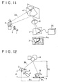
- Fig. 11 shows an exemplary conventional apparatus which carries out such distance measuring method.
- an infrared or similar laser beam emitted from a laser light source 1 is formed into slit light via an optical device 2.
- the slit laser light is then reflected by a scanning mirror 3 consisting of a galvano mirror or the like disposed at a predetermined position.
- the slit light 3S thus reflected from the scanning mirror 3 scans the surface of a three-dimensional object 4, which is to be measured, with rotation of the mirror 3.
- the slit light reflected from the object 4 is focused on an image pickup plane 7 via an optical device 6.
- a controller 5C comprising a differentiator, an integrator and other components
- the rotational position of the scanning mirror 3 is detected by finding the point in time when the slit light reflected from the object 4 passes through each of the image sensing cells, i.e., light receiving cells P ij arranged two-dimensionally on the image pickup plane 7.
- the distance up to the object 4 is measured trigonometrically per sensing cell P ij on the image pickup plane 7 from the positional relationship among the rotational position of the scanning mirror 3, the image pickup plane 7 and the scanning mirror 3.
- Such conventional apparatus are disclosed in document US 4,794,262 and document Araki K. et al.: "High Speed and Continuous Rangefinding System", IEICE Transactions, vol. E74, no. 10, 1 October 1991.
- Fig. 12 schematically shows the principle of measuring three-dimensional coordinate positions on the surface of the object 4 according to the method of triangulation.
- the distance Z ij from the image pickup plane 7 to one surface position on the object 4 whose reflected slit light is focused on the sensing cell P ij of the image pickup plane 7 can be obtained trigonometrically from Eq.
- the three parameters B ij , ⁇ ij and A in Eq. (1) are constants determined uniquely by the arrangement of the light source 1, the optical device 2, the scanning mirror 3, the optical device 6 and the image pickup plane 7.
- the angle ⁇ ij formed by the image pickup plane 7 and the slit light reflected 3S from the scanning mirror 3 can be obtained by, as mentioned, detecting the rotational position of the mirror 3 from the point in time when the slit light reflected from the object 4 passes through the sensing cell P i,j on the image pickup plane 7. Therefore it is possible to trigonometrically calculate the distance Z i,j from each cell on the image pickup plane 7 to the object 4.
- An object of the invention is to provide an improved distance measuring method and apparatus capable of performing accurate and fast measurements of positions on the surface of a three-dimensional object.
- a distance measuring method which scans the surface of an object with slit light while rotating a scanning mirror, and then detects the points in time when the slit light reflected from the object passes through sensing cells arranged on an image pickup plane, thereby measuring the positions on the surface of the object.
- This method comprises the steps of: calculating a count value C 1 indicative of a first angle difference between a first angle of the scanning mirror, where slit light reflected from a reference plane at a first position is incident upon a predetermined one out of a plurality of sensing cells arranged on an image pickup plane, and a second angle of the scanning mirror, where slit light reflected from the reference plane at a second position is incident upon the one sensing cell on the image pickup plane, the second position of the reference plane being spaced apart from the first position by a predetermined distance; calculating a count value C 2 indicative of a second angle difference between the second angle of the scanning mirror and a third angle of the scanning mirror, where slit light reflected from the reference plane at a third position is incident upon the one sensing cell on the image pickup plane, the third position of the reference plane being spaced apart by the same predetermined distance from the second position; calculating a count value C x indicative of a third angle difference between the third angle of the scanning mirror and a fourth angle of the scanning
- a distance measuring apparatus scans the surface of an object with slit light while rotating a scanning mirror, and then detects the points in time when the slit light reflected from the object passes through sensing cells arranged on an image pickup plane, thereby measuring the positions on the surface of the object.
- This apparatus comprises a counter (e.g., counter 12 in Figs. 3 and 4) for outputting a count value indicative of the rotational angle of the scanning mirror; a first subtracter (e.g., subtracter 142A in Fig.
- a calculator for calculating the distance between the object and the first position on the basis of the outputs of the first, second, and third subtracters and the parameter representing the relationship between the rotational angle of the scanning mirror and the output count value of the counter.
- the following advantageous effects are achievable.
- the distance to the object can be measured fast with high precision due to the procedure of calculating a count value C 1 indicative of a first angle difference between a first angle of the scanning mirror, where the slit light reflected from a reference plane at a first position is incident upon a predetermined one of sensing cells arranged on an image pickup plane, and a second angle of the scanning mirror, where the slit light reflected from the reference plane at a second position is incident upon the sensing cell on the image pickup plane, the second position of the reference plane being spaced apart from the first position by a predetermined distance; calculating a count value C 2 indicative of a second angle difference between the second angle of the scanning mirror and a third angle of the scanning mirror, where the slit light reflected from the reference plane at a third position is incident upon the sensing cell on the image pickup plane, the third position of the reference plane being spaced apart from the second position thereof by the same predetermined distance; calculating a count value C x indicative of a third angle difference between
- the distance to the object can be measured fast with high precision due to the constitution which comprises a counter for outputting a count value indicative of the rotational angle of the scanning mirror, a first subtracter for calculating the difference between the output count value of the counter indicative of the first angle of the scanning mirror, where the slit light reflected from a reference plane at a first position is incident upon a predetermined one of the sensing cells arranged on the image pickup plane, and the output count value of the counter indicative of the second angle of the scanning mirror, where the slit light reflected from the reference plane at a second position is incident upon the sensing cell on the image pickup plane, the second position of the reference plane being spaced apart from the first position thereof by a predetermined distance; a second subtracter for calculating the difference between the output count value of the counter indicative of the second angle of the scanning mirror and the output count value of the counter indicative of a third angle of the scanning mirror, where the slit light reflected from the reference plane at a third position is incident upon the sens
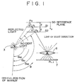
- Fig. 1 illustrates the principle operation adopted in the distance measuring method and apparatus of the invention and Fig. 2 shows the details of the partial geometric relationship in Fig. 1.
- a point in time is detected when slit light reflected from a reference plane set at the first plane position S0 is incident upon (i.e., passed through) each of sensing cells arrayed on an image pickup plane 7.
- a point in time is detected when slit light reflected from the reference plane at a second plane position S1, which is spaced apart by a predetermined distance d from the first plane position S0 and is in parallel therewith, is incident upon each sensing cell on the image pickup plane.
- another point in time is detected when slit light reflected from the reference plane at a third plane position S2, which is spaced apart the same predetermined distance d from the second plane position S1, is incident upon each sensing cell on the image pickup plane 7.
- a scanning mirror 3 is rotated around a center point M 0 at a constant velocity, and an angle ⁇ ⁇ from the original position of the rotating mirror 3 is given by Eq. (3) on the basis of a counter output value C ⁇ which is reset at the original position.
- ⁇ ⁇ k x C ⁇
- the image sensing (light receiving) cells P i,j are arranged two-dimensionally on the image pickup plane 7, and each cell has a specific line of sight direction dependent on an optical device 6, which may be a lens.
- the distance from the reference plane at the first plane position S0 is measured to a point on the surface of the object which intersects the line of sight direction of each cell.
- P 0 , P 1 and P 2 denote the points where the line of sight direction of one sensing cell P i,j on the image pickup plane 7 intersects the reference plane set at the first, second and third plane positions S0, S1 and S2.
- Angles ⁇ S0 , ⁇ S1 and ⁇ S2 denote the angles from the original position of the scanning mirror 3 when the slit light is incident upon such points P 0 , P 1 and P 2 respectively.
- the relationship between the distance a from point P 0 to P 1 and the distance a from point P 1 to P 2 is expressed as Eq. (4).
- Eqs. (10), (11) and (12) represent the relationship between the length B of the segment P 2 P f and the length C of the segment M 0 P f .
- Eq. (13) is obtained from Eqs. (10), (11) and (12).
- tan ⁇ B 2tan ⁇ 2 - tan( ⁇ 1 + ⁇ 2 ) tan ⁇ 2 tan( ⁇ 1 + ⁇ 2 )
- the distance x from the reference plane at the first plane position S0 to the target point P x on the surface of the object being measured is expressed as Eq. (17) on the basis of Eqs. (3), (4), (9) and (16).
- x 2 dtan ( kC 2 )(tan( kC 1 + kC 2 ) - tan( kC x )) tan( kC x ) tan( kC 1 + kC 2 ) - 2tan( kC x ) tan( kC 2 ) + tan( kC 2 ) tan( kC 1 + kC 2 )
- the count value C 1 indicates the angle difference ⁇ 1 between the angle ⁇ S0 of the scanning mirror 3, where the slit light reflected from the reference plane at the first plane position S0 is incident upon the sensing cell P i,j on the image pickup plane, and the angle ⁇ S1 of the scanning mirror 3, where the slit light reflected from the reference plane at the second plane position Sl, which is spaced apart by a predetermined distance d from the first plane position S0, is incident upon the sensing cell P i,j on the image pickup plane 7.
- the count value C 2 indicates the angle difference ⁇ 2 between the angle ⁇ S1 of the scanning mirror 3 and the angle ⁇ S2 of the scanning mirror 3, where the slit light reflected from the reference plane at the third plane position S2, which is spaced apart from the second plane position S1 by the same distance d, is incident upon the sensing cell P i,j on the image pickup plane 7.
- the count value C x indicates the angle ⁇ x which is the difference between the angle ⁇ S2 of the scanning mirror 3 and the angle ⁇ Sx of the scanning mirror 3, where the slit light reflected from the surface of the object is incident upon the sensing cell P i,j on the image pickup plane 7.
- the parameter k representing the relationship between the rotational angle of the scanning mirror 3 and the count value, can be obtained from Eq. (17) under the condition where the reference plane is set at the previously known position other than the aforementioned first, second and third plane positions S0, Sl and S2.
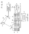
- Fig. 3 shows a preferred embodiment of the distance measuring apparatus according to the present invention.
- slit light 3S emitted from a slit light generating laser 1 is reflected via a scanning mirror 3 consisting of, for example, a galvano mirror so that the slit light 3S is sequentially scanned by a reference plane set at a second position S1 in Fig. 1, subsequently a reference plane set at a third plane position S2 in Fig. 1, and finally a three-dimensional object 4 to be measured.
- the slit light generating laser 1 may consist of a semiconductor laser which produces an output beam of 670 nm in wavelength (10mW at the outside of a lens, and approximately 1 mm in slit-light width).
- Practically an optical device 2 for forming the output beam of the light source 1 into a slit is also provided in the actual apparatus, but such optical device 2 is not shown in Fig. 3 for the purpose of simplifying the illustration.
- the slit light reflected sequentially from the reference plane at the first plane position S0 in Fig. 1, the reference plane at the second plane position Sl in Fig. 1, the reference plane at the third plane position S2 in Fig. 1 and the surface of the object 4 is projected successively onto an image pickup plane 7 via a lens 6 of an image sensor 5.
- the image pickup plane 7 is comprised of a plurality of sensing cells 8 arrayed thereon two-dimensionally. Each sensing cell 8 produces an output signal when the slit light 2 has passed through the reference plane or the object 4 in the line of sight direction, i.e., when the slit light reflected from the reference plane or the object 4 has passed through the slit light itself.
- the output signal of each sensing cell 8 is read by a reader 9, and the count value obtained from a counter 12 is stored in a memory cell 10P of a count value memory 10 which corresponds to the sensing cell 8 having outputted the signal.
- the individual operations of counting up the signals in the counter 12, outputting the signals from the sensing cells 8, and storing the count value in the memory cells 10P are performed in synchronism with an external clock signal 13 (having a frequency of about, e.g., 100 kHz).
- the output of the counter 12 corresponds to the angle data obtained from the mirror 3.
- a processor 14 computes the distance from the first plane position in Fig. 1 to the surface of the object on the basis of the count value stored in each memory cell 10P.
- a scanning mirror controller 15 outputs a reset signal (e.g., at about 60 Hz) every scan of the mirror 3 to thereby reset the contents of the counter 12 and the count value memory 10.
- a reset signal e.g., at about 60 Hz
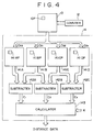
- FIG. 4 shows an exemplary constitution of the processor 14 in Fig. 3.
- a memory plane 141A consists of memory cells equal in number to the cells of the count value memory 10.
- Each memory cell 141AP receives, from the cell 10P of the count value memory 10, a count value C S0 which indicates the angle ⁇ S0 of the scanning mirror 3 where the slit light reflected from the reference plane at the first plane position S0 is incident upon the cell P i,j on the image pickup plane 7.
- the count value C S0 thus received is stored in the memory cell 141AP.
- a memory plane 141B consists of memory cells equal in number to the cells of the count value memory 10.
- Each memory cell 141BP receives, from the cell 10P of the count value memory 10, a count value C S indicative of the angle ⁇ S of the scanning mirror 3 where the slit light reflected from the reference plane at the second plane position Sl, which is spaced apart by a distance d from the first plane position, is incident upon the sensing cell P i,j on the image pickup plane 7.
- the count value C S1 thus received is stored in the memory cell 141BP.
- a memory plane 141C consists of memory cells equal in number to the cells of the count value memory 10.
- Each memory cell 141CP receives, from the cell 10P of the count value memory 10, a count value C S2 indicative of the angle ⁇ S2 of the scanning mirror 3 where the slit light reflected from the reference plane at the third plane position S2, which is spaced apart by the same distance d from the second plane position, is incident upon the sensing cell P i,j on the image pickup plane 7.
- the count value C S2 thus received is stored in the memory cell 141CP.
- a memory plane 141D consists of memory cells equal in number to the cells of the count value memory 10.
- Each memory cell 141DP receives, from the cell 10P of the count value memory 10, a count value C Sx which indicates the angle ⁇ Sx of the scanning mirror 3 where the slit light reflected from the surface of the object 4 is incident upon the sensing cell P i,j on the image pickup plane 7.
- the count value C Sx thus received is stored in the memory cell 141DP.
- a subtracter 142A calculates the difference C 1 between the output count value C S0 of the memory plane 141A and the output count value C S1 of the memory plane 141B, and then supplies the difference C 1 to a calculator 143.
- a subtracter 142B calculates the difference C 2 between the output count value C S1 of the memory plane 141B and the output count value C S2 of the memory plane 141C, and supplies the difference C 2 to the calculator 143.
- a subtracter 142C calculates the difference C x between the output count value C S2 of the memory plane 141C and the output count value C Sx of the memory plane 141D, and supplies the difference C x to the calculator 143.
- the calculator 143 receives the parameter k together with the count values C 1 , C 2 and C x from the subtracters 142A, 142B and 142C respectively and calculates the distance x by executing Eq. (17).
- Eq. (17) is executed by the calculator 143.
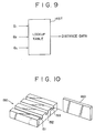
- the desired distance can be obtained faster by another procedure which comprises the steps of previously calculating the distances x relative to the count values C 1 , C 2 and C x possibly assumable with regard to the individual sensing cells 8 (P i,j ) on the image pickup plane 7.
- Such distances are then stored in the lookup table 143T shown in Fig. 5 and the distance x is output from the lookup table 143T in response to each of the count values C 1 , C 2 and C x received from the subtracters 142A, 142B and 143C in Fig. 4.
- the variable is the count value C x alone, so that the distance x can be obtained merely by inputting the count value C x only as in the lookup table 144T of Fig. 6.
- first, second and third plane positions S0, Sl and S2 are determined to be parallel with the image pickup plane 7, i.e., in case each reference plane is set to be parallel with the image pickup plane 7, the same lookup table is commonly usable for a plurality of sensing cells arranged vertically on the image pickup plane 7. More specifically, when 8 sensing cells are arranged horizontally on the image pickup plane 7 as shown in Fig. 7, the requirement is satisfied by preparing only 8 lookup tables 144Tl, 144T2, 144T3, .... 144T8.
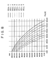
- Fig. 8 shows exemplary contents of a lookup table prepared for converting into a distance the count values of 8 horizontal sensing cells on an 8 x 16 image pickup plane (consisting of 8 horizontal cells x 16 vertical cells).
- the length a is set to 90 mm, and each distance shown is from the first plane position S0 which is spaced apart approximately by 33 cm from the image pickup plane of a camera.
- the distance x is obtained by executing the calculation of Eq. (17) in the calculator 143 of Fig. 4 on the basis of the count values C 1 , C 2 and C x , or by using the lookup table 143T or 144T of Fig. 5 or 6.
- the distance x may be obtained by using, besides the count values C 1 , C 2 and C x described above, any other value indicating the rotation angles ⁇ 1 , ⁇ 2 and ⁇ x of the scanning mirror 3.
- setting of the reference plane at the mutually parallel and equidistant first, second and third positions S0, Sl and S2 can be achieved by providing, as illustrated in Fig. 10, a position setting jig 150 which has mutually parallel and equidistant grooves 151, 152 and 153 corresponding respectively to the first, second and third plane positions S0, Sl and S2, and then placing a reference plane plate 160 sequentially in such grooves 151, 152 and 153.
- the parameter k is calculated according to Eq. (17) under the condition where the reference plane is set at the previously known plane position other than the first, second and third plane positions S0, Sl and S2.
- the reference plane is set at the previously known plane position other than the first, second and third plane positions S0, Sl and S2.
- the distance measurement can be performed also by setting the reference plane at four or more plane positions which are mutually parallel and equidistant.
- each three-dimensional coordinate position on the surface of the object is calculated with reference to the first plane position S0, it is also possible to obtain the three-dimensional coordinate position on the object surface with reference to the position of the distance measuring apparatus by previously finding the positional relationship between the first plane position and the distance measuring apparatus.
Landscapes
- Physics & Mathematics (AREA)
- Engineering & Computer Science (AREA)
- Electromagnetism (AREA)
- Computer Networks & Wireless Communication (AREA)
- General Physics & Mathematics (AREA)
- Radar, Positioning & Navigation (AREA)
- Remote Sensing (AREA)
- Length Measuring Devices By Optical Means (AREA)
- Measurement Of Optical Distance (AREA)
- Image Processing (AREA)
- Image Analysis (AREA)
Claims (6)
- Abstandsmeßverfahren zur Messung von Abständen zu Positionen auf einer Oberfläche eines dreidimensionalen Objekts (4) durch Abtasten der Oberfläche des betreffenden Objekts mittels Spaltlicht (3S) während des Drehens eines Abtastspiegels (3) und Ermitteln der Punkte zu der Zeit, zu der das von dem betreffenden Objekt reflektierte Spaltlicht in einer Bildaufnahmeebene (7) angeordnete Abtastzellen (Pij) überstreicht, gekennzeichnet durch die Schritte:Berechnen eines Zählwertes (C1), der kennzeichnend ist für eine erste Winkeldifferenz (1) zwischen einem ersten Winkel (SO) des Abtastspiegels, wobei das von einer Referenzebene in bzw. an einer ersten Position (SO) reflektierte Spaltlicht auf eine bestimmte Abtastzelle der Abtastzellen einfällt, die in der Bildaufnahmeebene angeordnet sind, und einem zweiten Winkel (Sl) des betreffenden Abtastspiegels, wobei das von der Referenzebene in bzw. an einer zweiten Position (S1) reflektierte Spaltlicht auf die genannte eine Abtastzelle in der Bildaufnahmeebene einfällt und wobei die zweite Position der Referenzebene um einen bestimmten Abstand (d) von der genannten ersten Position in Abstand vorgesehen ist;Berechnen eines Zählwerts (C2), der kennzeichnend ist für eine zweite Winkeldifferenz (2) zwischen dem zweiten Winkel (S1) des genannten Abtastspiegels und einem dritten Winkel (S2) des betreffenden Abtastspiegels, wobei das von der Referenzebene in bzw. an einer dritten Position reflektierte Spaltlicht auf die genannte eine Abtastzelle in der Bildaufnahmeebene einfällt und wobei die genannte dritte Position der Referenzebene um den genannten bestimmten Abstand (d) von der genannten zweiten Position in Abstand vorgesehen ist; Berechnen eines Zählwerte (Cx), der kennzeichnend ist für eine dritte Winkeldifferenz (x) zwischen dem dritten Winkel des Abtastspiegels und einem vierten Winkel (3x) des betreffenden Abtastspiegels, wobei das von der Oberfläche des zu messenden Objekts reflektierte Licht auf die genannte eine Abtastzelle in der Bildaufnahmeebene einfällt;Berechnen eines Parameters (k), der kennzeichnend ist für eine Beziehung zwischen einem Drehwinkel des genannten Abtastspiegels und einem Zählwert;und Berechnen eines Abstands (x) zwischen der genannten ersten Position und dem genannten Objekt aus der folgenden Gleichung:
- Abstandsmeßverfahren nach Anspruch 1, dadurch gekennzeichnet, dass der Schritt des Berechnens des Abstands (x) zwischen dem genannten Objekt (4) und der genannten ersten Position (S0) den Schritt der Verwendung einer Nachschlagtabelle (143T; 144T; 144T1, 144T2..., 144T8) umfaßt.
- Abstandsmeßverfahren nach Anspruch 1, dadurch gekennzeichnet, dass der Abstand (x) zwischen dem genannten Objekt (4) und der genannten ersten Position (S0) mehrmals berechnet wird, während der genannte Abtastspiegel (3) gedreht wird, derart, dass eine äußere Form des genannten Objekts gemessen wird.
- Vorrichtung zur Messung von Abständen zu Positionen auf einer Oberfläche eines dreidimensionalen Objekts (4), umfassend einen Abtastspiegel (3), eine Einrichtung zur Drehung des genannten Abtastspiegels und eine Zähleinrichtung (12) zur Abgabe eines Zählwerts, der kennzeichnend ist für den Drehwinkel des genannten Abtastspiegels,
dadurch gekennzeichnet, dass ferner eine erste Subtraktionseinrichtung (142A) vorgesehen ist zur Berechnung der Differenz (C1) zwischen einem ersten Zählwert (CS0) der betreffenden Zähleinrichtung, der kennzeichnend ist für einen ersten Winkel (S0) des Abtastspiegels, wobei von einer Referenzebene in bzw. an einer ersten Position (S0) reflektiertes Spaltlicht auf eine bestimmte Abtastzelle aus einer Vielzahl von Abtastzellen (Pij) einfällt, die in einer Bildaufnahmeebene (7) angeordnet sind, und einem zweiten Zählwert (CS1) der Zähleinrichtung, der kennzeichnend ist für einen zweiten Winkel (S1) des betreffenden Abtastspiegels, wobei von der Referenzebene in bzw. an einer zweiten Position (S1) reflektiertes Spaltlicht auf die genannte eine Abtastzelle in der Bildaufnahmeebene einfällt und
wobei die genannte zweite Position der Bildaufnahmeebene um einen bestimmten Abstand (d) von der genannten ersten Position in Abstand vorgesehen ist;dass eine zweite Subtraktionseinrichtung (142B) vorgesehen ist zur Berechnung der Differenz (C2) zwischen dem zweiten Zählwert (CS1) der genannten Zähleinrichtung, der kennzeichnend ist für den zweiten Winkel (S1) des Abtastspiegels, und einem dritten Zählwert (CS2) der Zähleinrichtung, der kennzeichnend ist für einen dritten Winkel (S2) des betreffenden Abtastspiegels, wobei von der Referenzebene in bzw. an einer dritten Position (S2) reflektiertes Spaltlicht auf die genannte eine Abtastzelle in der Biidaufnahmeebene einfällt und wobei die genannte dritte Position der Bildaufnahmeebene um den genannten bestimmten Abstand (d) von der genannten zweiten Position in Abstand vorgesehen ist;dass eine dritte Subtraktionseinrichtung (142C) vorgesehen ist zur Berechnung der Differenz (Cx) zwischen dem dritten Zählwert (CS2) der Zähleinrichtung, der kennzeichnend ist für den dritten Winkel (S2) des Abtastspiegels, und einem vierten Zählwert (CSx) der Zähleinrichtung, der kennzeichnend ist für einen vierten Winkel (Sx) des Abtastspiegels, wobei von der Oberfläche des zu messenden Objekts reflektiertes Spaltlicht auf die genannte eine Abtastzelle in der Bildaufnahmeebene einfällt;und dass eine Recheneinrichtung (143) vorgesehen ist zur Berechnung des Abstands (x) zwischen dem genannten Objekt (4) und der genannten ersten Position (S0) durch Heranziehen der Ausgangssignale der ersten, zweiten und dritten Subtraktionseinrichtungen sowie eines Parameters (k), der kennzeichnend ist für die Beziehung zwischen dem Drehwinkel des genannten Abtastspiegels und dem Ausgangs-Zählwert der genannten Zähleinrichtung, wobei die genannte Recheneinrichtung (143) folgende Gleichung ausführt: - Abstandsmeßvorrichtung nach Anspruch 4, dadurch gekennzeichnet, dass die genannte Recheneinrichtung (143) eine Nachschlagtabelle (143T; 144T; 144T1, 144T2, ... 144T8) umfaßt.
- Abstandsmeßvorrichtung nach Anspruch 4, dadurch gekennzeichnet, dass die genannte Recheneinrichtung (143) den Abstand (x) zwischen dem genannten Objekt (4) und der genannten ersten Position (S0) mehrmals berechnet, während der Abtastspiegel (3) gedreht wird, derart, dass eine äußere Form des betreffenden Objekts gemessen wird.
Applications Claiming Priority (3)
| Application Number | Priority Date | Filing Date | Title |
|---|---|---|---|
| JP07292693A JP3175393B2 (ja) | 1993-03-08 | 1993-03-08 | 距離測定方法および装置 |
| JP72926/93 | 1993-03-08 | ||
| JP7292693 | 1993-03-08 |
Publications (3)
| Publication Number | Publication Date |
|---|---|
| EP0618461A2 EP0618461A2 (de) | 1994-10-05 |
| EP0618461A3 EP0618461A3 (de) | 1997-11-19 |
| EP0618461B1 true EP0618461B1 (de) | 2000-12-27 |
Family
ID=13503455
Family Applications (1)
| Application Number | Title | Priority Date | Filing Date |
|---|---|---|---|
| EP94400489A Expired - Lifetime EP0618461B1 (de) | 1993-03-08 | 1994-03-08 | Verfahren und Gerät zur Abstandsmessung |
Country Status (5)
| Country | Link |
|---|---|
| US (1) | US5436727A (de) |
| EP (1) | EP0618461B1 (de) |
| JP (1) | JP3175393B2 (de) |
| KR (1) | KR940022056A (de) |
| DE (1) | DE69426468T2 (de) |
Cited By (1)
| Publication number | Priority date | Publication date | Assignee | Title |
|---|---|---|---|---|
| WO2023019286A1 (en) * | 2021-08-20 | 2023-02-23 | Omniscient Neurotechnology Pty Limited | Measuring 3-dimensional distances in medical imaging data |
Families Citing this family (7)
| Publication number | Priority date | Publication date | Assignee | Title |
|---|---|---|---|---|
| GB2292605B (en) * | 1994-08-24 | 1998-04-08 | Guy Richard John Fowler | Scanning arrangement and method |
| US5778367A (en) | 1995-12-14 | 1998-07-07 | Network Engineering Software, Inc. | Automated on-line information service and directory, particularly for the world wide web |
| US5826014A (en) | 1996-02-06 | 1998-10-20 | Network Engineering Software | Firewall system for protecting network elements connected to a public network |
| US5898830A (en) * | 1996-10-17 | 1999-04-27 | Network Engineering Software | Firewall providing enhanced network security and user transparency |
| JP3417377B2 (ja) * | 1999-04-30 | 2003-06-16 | 日本電気株式会社 | 三次元形状計測方法及び装置並びに記録媒体 |
| US6421132B1 (en) | 1999-10-15 | 2002-07-16 | Vladimir M. Brajovic | Method and apparatus for rapid range imaging |
| US7107144B2 (en) | 2003-02-27 | 2006-09-12 | Spectra Research, Inc. | Non-intrusive traffic monitoring system |
Family Cites Families (9)
| Publication number | Priority date | Publication date | Assignee | Title |
|---|---|---|---|---|
| US4158507A (en) * | 1977-07-27 | 1979-06-19 | Recognition Equipment Incorporated | Laser measuring system for inspection |
| US4325639A (en) * | 1980-02-04 | 1982-04-20 | H. A. Schlatter Ag | Method for measuring distances and apparatus for performing the method |
| US4936676A (en) * | 1984-11-28 | 1990-06-26 | Honeywell Inc. | Surface position sensor |
| US4794262A (en) * | 1985-12-03 | 1988-12-27 | Yukio Sato | Method and apparatus for measuring profile of three-dimensional object |
| JPS633212A (ja) * | 1986-06-24 | 1988-01-08 | N T T Gijutsu Iten Kk | 計測装置 |
| JPH0718692B2 (ja) * | 1989-06-16 | 1995-03-06 | 三菱電機株式会社 | 光切断法による物体の立体形状検知装置 |
| JPH0718693B2 (ja) * | 1989-06-27 | 1995-03-06 | 三菱電機株式会社 | 光切断法による物体の立体形状検知装置 |
| US5022751A (en) * | 1989-08-21 | 1991-06-11 | Sundstrand Data Control, Inc. | Portable localizer siting system |
| US5129010A (en) * | 1989-12-15 | 1992-07-07 | Kabushiki Kaisha Toyoto Chuo Kenkyusho | System for measuring shapes and dimensions of gaps and flushnesses on three dimensional surfaces of objects |
-
1993
- 1993-03-08 JP JP07292693A patent/JP3175393B2/ja not_active Expired - Fee Related
-
1994
- 1994-03-01 US US08/203,567 patent/US5436727A/en not_active Expired - Lifetime
- 1994-03-07 KR KR1019940004368A patent/KR940022056A/ko not_active Withdrawn
- 1994-03-08 DE DE69426468T patent/DE69426468T2/de not_active Expired - Fee Related
- 1994-03-08 EP EP94400489A patent/EP0618461B1/de not_active Expired - Lifetime
Cited By (1)
| Publication number | Priority date | Publication date | Assignee | Title |
|---|---|---|---|---|
| WO2023019286A1 (en) * | 2021-08-20 | 2023-02-23 | Omniscient Neurotechnology Pty Limited | Measuring 3-dimensional distances in medical imaging data |
Also Published As
| Publication number | Publication date |
|---|---|
| EP0618461A2 (de) | 1994-10-05 |
| JPH06258042A (ja) | 1994-09-16 |
| US5436727A (en) | 1995-07-25 |
| JP3175393B2 (ja) | 2001-06-11 |
| DE69426468D1 (de) | 2001-02-01 |
| DE69426468T2 (de) | 2001-05-31 |
| EP0618461A3 (de) | 1997-11-19 |
| KR940022056A (ko) | 1994-10-20 |
Similar Documents
| Publication | Publication Date | Title |
|---|---|---|
| EP1493990B1 (de) | Vermessungsinstrument und elektronisches speichermedium | |
| US7787134B2 (en) | Multiple fanned laser beam metrology system | |
| EP1024342B1 (de) | Automatische Vermessungsgerät und Verfahren zum dreidimensionalen Messen | |
| EP0448111A2 (de) | Lidar-Abtast-System | |
| US7633609B2 (en) | Measuring system | |
| WO1990009561A2 (en) | Laser range imaging system using projective geometry | |
| CN110573928A (zh) | 光检测和测距系统中的角校准 | |
| US6172755B1 (en) | Three dimensional measurement system and pickup apparatus | |
| EP0618461B1 (de) | Verfahren und Gerät zur Abstandsmessung | |
| US20020089675A1 (en) | Three-dimensional input device | |
| JPH102722A (ja) | 三次元位置計測装置 | |
| US6421114B1 (en) | Three-dimensional information measuring apparatus | |
| JP2001296124A (ja) | 3次元座標計測方法及び3次元座標計測装置 | |
| JP2001051058A (ja) | 距離測定装置 | |
| JP2001221636A (ja) | 3次元座標計測方法及び計測装置 | |
| JPH11173840A (ja) | 測距装置及び測距方法 | |
| JP7324097B2 (ja) | 3次元測量装置、3次元測量方法および3次元測量プログラム | |
| JP3356321B2 (ja) | 物体の形状測定装置 | |
| JP2694647B2 (ja) | 測距経緯儀 | |
| JPH11230699A (ja) | 弾丸の標的到達位置計測装置 | |
| JPH07190773A (ja) | 光学式3次元位置検出装置 | |
| JPS6010563B2 (ja) | 平板の平坦度測定方法 | |
| Golnabi | Design and operation of a laser scanning system | |
| JPH0798429A (ja) | 距離計測装置 | |
| JP3112538B2 (ja) | 光学的三次元形状測定方法と測定装置 |
Legal Events
| Date | Code | Title | Description |
|---|---|---|---|
| PUAI | Public reference made under article 153(3) epc to a published international application that has entered the european phase |
Free format text: ORIGINAL CODE: 0009012 |
|
| AK | Designated contracting states |
Kind code of ref document: A2 Designated state(s): DE FR GB |
|
| PUAL | Search report despatched |
Free format text: ORIGINAL CODE: 0009013 |
|
| AK | Designated contracting states |
Kind code of ref document: A3 Designated state(s): DE FR GB |
|
| 17P | Request for examination filed |
Effective date: 19980507 |
|
| 17Q | First examination report despatched |
Effective date: 19990408 |
|
| GRAG | Despatch of communication of intention to grant |
Free format text: ORIGINAL CODE: EPIDOS AGRA |
|
| GRAG | Despatch of communication of intention to grant |
Free format text: ORIGINAL CODE: EPIDOS AGRA |
|
| GRAG | Despatch of communication of intention to grant |
Free format text: ORIGINAL CODE: EPIDOS AGRA |
|
| GRAH | Despatch of communication of intention to grant a patent |
Free format text: ORIGINAL CODE: EPIDOS IGRA |
|
| GRAH | Despatch of communication of intention to grant a patent |
Free format text: ORIGINAL CODE: EPIDOS IGRA |
|
| GRAA | (expected) grant |
Free format text: ORIGINAL CODE: 0009210 |
|
| AK | Designated contracting states |
Kind code of ref document: B1 Designated state(s): DE FR GB |
|
| REF | Corresponds to: |
Ref document number: 69426468 Country of ref document: DE Date of ref document: 20010201 |
|
| PGFP | Annual fee paid to national office [announced via postgrant information from national office to epo] |
Ref country code: DE Payment date: 20010228 Year of fee payment: 8 |
|
| PGFP | Annual fee paid to national office [announced via postgrant information from national office to epo] |
Ref country code: FR Payment date: 20010313 Year of fee payment: 8 |
|
| ET | Fr: translation filed | ||
| PLBE | No opposition filed within time limit |
Free format text: ORIGINAL CODE: 0009261 |
|
| STAA | Information on the status of an ep patent application or granted ep patent |
Free format text: STATUS: NO OPPOSITION FILED WITHIN TIME LIMIT |
|
| 26N | No opposition filed | ||
| REG | Reference to a national code |
Ref country code: GB Ref legal event code: IF02 |
|
| PG25 | Lapsed in a contracting state [announced via postgrant information from national office to epo] |
Ref country code: DE Free format text: LAPSE BECAUSE OF NON-PAYMENT OF DUE FEES Effective date: 20021001 |
|
| PG25 | Lapsed in a contracting state [announced via postgrant information from national office to epo] |
Ref country code: FR Free format text: LAPSE BECAUSE OF NON-PAYMENT OF DUE FEES Effective date: 20021129 |
|
| REG | Reference to a national code |
Ref country code: FR Ref legal event code: ST |
|
| PGFP | Annual fee paid to national office [announced via postgrant information from national office to epo] |
Ref country code: GB Payment date: 20070307 Year of fee payment: 14 |
|
| GBPC | Gb: european patent ceased through non-payment of renewal fee |
Effective date: 20080308 |
|
| PG25 | Lapsed in a contracting state [announced via postgrant information from national office to epo] |
Ref country code: GB Free format text: LAPSE BECAUSE OF NON-PAYMENT OF DUE FEES Effective date: 20080308 |