EP0618460B1 - System for determining the position and/or velocity of an object by means of surface wave identification tags, to be used especially for loading and handling systems - Google Patents
System for determining the position and/or velocity of an object by means of surface wave identification tags, to be used especially for loading and handling systems Download PDFInfo
- Publication number
- EP0618460B1 EP0618460B1 EP94104638A EP94104638A EP0618460B1 EP 0618460 B1 EP0618460 B1 EP 0618460B1 EP 94104638 A EP94104638 A EP 94104638A EP 94104638 A EP94104638 A EP 94104638A EP 0618460 B1 EP0618460 B1 EP 0618460B1
- Authority
- EP
- European Patent Office
- Prior art keywords
- identification
- distance
- objects
- antenna
- identification mark
- Prior art date
- Legal status (The legal status is an assumption and is not a legal conclusion. Google has not performed a legal analysis and makes no representation as to the accuracy of the status listed.)
- Expired - Lifetime
Links
- 238000011156 evaluation Methods 0.000 claims abstract description 18
- 238000000034 method Methods 0.000 claims description 10
- 230000008878 coupling Effects 0.000 claims description 3
- 238000010168 coupling process Methods 0.000 claims description 3
- 238000005859 coupling reaction Methods 0.000 claims description 3
- 238000010897 surface acoustic wave method Methods 0.000 claims description 3
- 238000013459 approach Methods 0.000 claims description 2
- 238000009826 distribution Methods 0.000 claims description 2
- 239000000725 suspension Substances 0.000 claims 1
- 238000005259 measurement Methods 0.000 abstract description 6
- 238000001514 detection method Methods 0.000 abstract description 5
- 230000010363 phase shift Effects 0.000 abstract description 2
- 230000005540 biological transmission Effects 0.000 description 4
- 238000010586 diagram Methods 0.000 description 4
- 238000011161 development Methods 0.000 description 2
- 230000018109 developmental process Effects 0.000 description 2
- 238000001208 nuclear magnetic resonance pulse sequence Methods 0.000 description 2
- 238000003860 storage Methods 0.000 description 2
- 239000000758 substrate Substances 0.000 description 2
- WSMQKESQZFQMFW-UHFFFAOYSA-N 5-methyl-pyrazole-3-carboxylic acid Chemical compound CC1=CC(C(O)=O)=NN1 WSMQKESQZFQMFW-UHFFFAOYSA-N 0.000 description 1
- 238000010276 construction Methods 0.000 description 1
- 230000003111 delayed effect Effects 0.000 description 1
- 238000002592 echocardiography Methods 0.000 description 1
- 238000005538 encapsulation Methods 0.000 description 1
- 238000009434 installation Methods 0.000 description 1
- GQYHUHYESMUTHG-UHFFFAOYSA-N lithium niobate Chemical compound [Li+].[O-][Nb](=O)=O GQYHUHYESMUTHG-UHFFFAOYSA-N 0.000 description 1
- 238000012423 maintenance Methods 0.000 description 1
- 238000004519 manufacturing process Methods 0.000 description 1
- 239000000463 material Substances 0.000 description 1
- 238000012545 processing Methods 0.000 description 1
- 230000005855 radiation Effects 0.000 description 1
Images

Classifications
-
- G—PHYSICS
- G01—MEASURING; TESTING
- G01S—RADIO DIRECTION-FINDING; RADIO NAVIGATION; DETERMINING DISTANCE OR VELOCITY BY USE OF RADIO WAVES; LOCATING OR PRESENCE-DETECTING BY USE OF THE REFLECTION OR RERADIATION OF RADIO WAVES; ANALOGOUS ARRANGEMENTS USING OTHER WAVES
- G01S13/00—Systems using the reflection or reradiation of radio waves, e.g. radar systems; Analogous systems using reflection or reradiation of waves whose nature or wavelength is irrelevant or unspecified
- G01S13/74—Systems using reradiation of radio waves, e.g. secondary radar systems; Analogous systems
- G01S13/75—Systems using reradiation of radio waves, e.g. secondary radar systems; Analogous systems using transponders powered from received waves, e.g. using passive transponders, or using passive reflectors
- G01S13/751—Systems using reradiation of radio waves, e.g. secondary radar systems; Analogous systems using transponders powered from received waves, e.g. using passive transponders, or using passive reflectors wherein the responder or reflector radiates a coded signal
- G01S13/755—Systems using reradiation of radio waves, e.g. secondary radar systems; Analogous systems using transponders powered from received waves, e.g. using passive transponders, or using passive reflectors wherein the responder or reflector radiates a coded signal using delay lines, e.g. acoustic delay lines
-
- B—PERFORMING OPERATIONS; TRANSPORTING
- B66—HOISTING; LIFTING; HAULING
- B66C—CRANES; LOAD-ENGAGING ELEMENTS OR DEVICES FOR CRANES, CAPSTANS, WINCHES, OR TACKLES
- B66C13/00—Other constructional features or details
- B66C13/18—Control systems or devices
- B66C13/46—Position indicators for suspended loads or for crane elements
-
- G—PHYSICS
- G01—MEASURING; TESTING
- G01S—RADIO DIRECTION-FINDING; RADIO NAVIGATION; DETERMINING DISTANCE OR VELOCITY BY USE OF RADIO WAVES; LOCATING OR PRESENCE-DETECTING BY USE OF THE REFLECTION OR RERADIATION OF RADIO WAVES; ANALOGOUS ARRANGEMENTS USING OTHER WAVES
- G01S5/00—Position-fixing by co-ordinating two or more direction or position line determinations; Position-fixing by co-ordinating two or more distance determinations
- G01S5/02—Position-fixing by co-ordinating two or more direction or position line determinations; Position-fixing by co-ordinating two or more distance determinations using radio waves
- G01S5/0247—Determining attitude
Definitions
- the present invention relates to a detection system the relative position and / or the relative movement two objects to each other, by means of radio-technical location using passive surface wave identification marks (ID tag).
- ID tag passive surface wave identification marks
- the system according to the invention is in particular for operating areas with loading and handling with Chargers and / or hoists for moving loads as such relevant objects.
- loads / objects are special Containers, whose transshipment with e.g. Crane systems using of the system according to the invention, at least to the extent that it is automatic is feasible that the accuracy and precision of the Controlling the chargers and objects to each other no longer depends on the skill of the people involved.
- ID tags use the one on a piezoelectric substrate body existing surface wave stripe structure with an electromechanical / mechanoelectric Interdigital converter structure and a reflector structure and one to the transducer structure connected input / output antenna.
- ID tags / identification marks are passive working elements with electrical input and output, but acoustomechanical Functionality. To function as intended, need they don't have their own power supply. They are extraordinary in construction robust and work due to their hermetic encapsulation practically completely independent of dirt. she are therefore suitable even for very rough technical operations in even a hostile environment.
- Such identification marks have at the remote-queryable built by Siemens The toll system of the city's highway system Oslo large-scale application found. They are very inexpensive to manufacture, do not require any maintenance in operation and are extremely durable without losing its precision.
- Such passive identification marks are used as follows: With an interrogation device, radio pulses in the decimeter wave range are continuously transmitted via its transmitting antenna. In the range of the transmitter, this identification mark receives this radio pulse (burst) by means of its input antenna, from which the received pulse signal is fed to the converter already mentioned. With the reflector present in the identification mark, a characteristic pulse sequence pattern is impressed on the surface acoustic wave generated by the transducer in the reflector. The pattern can be determined or determined by the chosen structure of the reflector. With conventional identification marks of this type, the variety, ie the number of possible codings, is a multiple of 10 9 possibilities.
- an electromagnetic (response) signal is sent back to the antenna (previously used as a transmitting antenna), which is now used as the receiving antenna of the evaluation device, via the antenna of the identification mark.
- Impulse response consists of one of the specified coding the pulse sequence corresponding to the reflector structure with a Carrier frequency that is either equal to the transmit frequency or their deviation from the transmission frequency a further signal information is how this is described below becomes.
- the impulse response is advantageously the identification mark delayed by approximately 1 ⁇ s compared to the transmission pulse. Any echoes from the nearby area, which are much earlier can receive the receiving antenna of the evaluation device can easily be hidden in time. Interference from Echo signals are not a problem here. Otherwise, the Query distance advantageously limited and limited, so that problems with spatially adjacent radio / high-frequency systems are at least easily manageable.
- a system for determining the distance of objects is known from WO 90/15343, with which the removal of a passive SAW transponder attached to the object (Identification mark with surface wave component) in the detection cone a query signal can be determined.
- a charging device with a sensor arrangement is known from WO 90/09336, which determines the relative position of a container to the loading device.
- Several sensors on the charging harness each measure by reflecting one Send signal the distance to the container, so that the positioning of the Loading harness can be controlled automatically.
- the object of the present invention is to use identification marks to provide an alternative system and method, with which the loading business can be automated and / or carried out with greater precision is when this is usually human-executable.
- the present invention relates to advantageous use such passively working surface identification marks for contactless identification and for recognizing positions and / or movement speeds of e.g. Containers or the like, as they are used regularly in transportation Find.
- identification marks as described above (with surface wave structure and input / output antenna) on featured positions e.g. to place such containers on their outer surface, e.g. to stick, to attach or the like can also vehicles or their cargo areas with each one or more such identification marks his.
- the system according to the invention is essentially also possible about how in a sensible way with such in principle already known identification marks worked advantageously and which evaluations are to be provided or carried out are e.g. the loading gear of a crane, by the crane operator roughly controlled, with high precision automatically on e.g. the To bring the loading eyelets of a container down to the cm, and this even with relatively poor visibility, e.g. in night mode.
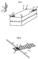
- FIG. 1 shows, designated C, a container with eyelets 7 for attaching a crane hook 8 to a loading harness L. With 1 and 1 'two identification marks are designated as they will be described in more detail below. With 9 it is Transmitting / receiving antenna of an interrogation / evaluation device.
- 1 is an identification tag also known as an ID tag shown schematically.
- substrate body made preferably piezoelectric strongly coupling material such as lithium niobate, tantalate and the like.
- Striped structure On the surface of the with 2 designated substrate body made preferably piezoelectric strongly coupling material such as lithium niobate, tantalate and the like, there is a photolithographically applied one Striped structure.
- the portion of this stripe structure denoted by 3 is the digital converter, at its electrical connections the dipoles of antenna 4 are connected.
- With 5 is the stripe structure of the reflector.
- a in practice, such reflector structure 5 has several 100 in periodically arranged reflector strips, from which the large number of coding options can be seen.
- Figure 3 shows that in the impulse response of the identification mark 1 contained pulse train 10 (envelope), which is the response of the Coding of the reflector structure 5 on a received burst 11 is.
- pulse train 10 envelope
- the change in the time interval between the burst pulse 11 and the response pulses 10, starting from a predetermined one Value for a known distance is a reference for a change in the spatial distance between the antennas 9 and 4 of the two objects, e.g. between the charging harness L and the location of the responding identification marks 1 or 1 '.
- the amplitude levels of the pulse peaks 10 and 11 are not shown to scale to one another.
- the invention relates to the detection of the relative position two objects to each other, namely one on the storage bin parked container C as e.g. one object and one Loading harnesses L of a crane as e.g. the other object.
- the container as a rule stands still and only the loading gear is moved.
- a further development of the invention relates to detection of the movement, specifically the speed of movement of two objects relative to each other.
- the evaluation takes place under Use of the resulting speed values, e.g. alone of the loading gear when the container is stationary and parked.
- both evaluations can be used.
- one object e.g. the Containers to affix several identification marks.
- This several identification marks are to be placed in such a way that they mark relevant locations of the container. For example is a (respective) identification mark near an eyelet 7 attached for hooking the load harness.
- a (respective) identification mark near an eyelet 7 attached for hooking the load harness.
- the signal processing knowing the pattern, i. h. must know which parts of the container this is by definition are. If several identification marks 1, 1 'are provided, so they advantageously have different coding, so that they are distinguishable for the evaluation device are recognizable.
- identification marks 1, 1 'with different Coding also with different forms or assembly means to provide.
- the shot on object C has the corresponding form.
- these two Identification marks base plates, with their rectangular Form each corner is cut off. With one or the like measure can be achieved that a respective identification mark with a specific coding unmistakable only on an optionally specified one Can be attached to the container.
- the antenna 9 of the query / evaluation device for transmitting the Query pulse signal and attached to receive the pulse signal.
- the (straight) distance can be measured with just one measurement between the antenna 9 and the identification mark 1, 1 'can be roughly determined. This current distance results from the time delay that the impulse response is due to back and forth distance distance required. Become the distances from the transmitting / receiving antenna 9 at least three identification marks attached to the container at predetermined locations (with different coding) measured, can the position of the antenna 9, i.e. the position of the lifting gear, clearly determined in relation to the container become. So that the lifting gear can automatically on the Containers are brought, and also on the correct container if taken into account in the evaluation which container which encodings of its individual Has identification marks.
- the relative speed of the two objects to one another result in Doppler frequency shifts in the carrier frequency of the impulse response signal.
- the received carrier frequency is the impulse response at the transmission frequency f S f S +/- ⁇ f .
- the Doppler frequency shift ⁇ f is very small and the phase shift ⁇ is evaluated for evaluation.
- ⁇ 2 . 2 ⁇ ⁇ r / ⁇ where ⁇ is the wavelength of the transmission frequency of the interrogation pulse.
- the factor 2 in turn is based on the double passage of the distance / r /.
- Another evaluation measure according to the invention is to determine the course and the sign of the Doppler speed and the change in the phase angle ⁇ and to use them to determine the relative position of this antenna and the identification mark.
- the transmitting / receiving antenna 9 moving at a speed v at a distance past the identification mark 1 queried in each case can be seen from the distance ⁇ x of the antenna on the path of the antenna between two measurements and the change in the distance ⁇ r between this antenna 9 and determine the distance a from the identification mark in which this antenna is moved past the identification mark on its path of movement.
- This distance variable a defined in this way cannot be determined by evaluating the Doppler shift, because this distance a is directed perpendicular to the relative movement of the antenna, that is to say the Doppler shift at this point is zero.
- the calculation of the intersection of the radiation of the interrogation pulses emitted by the movement path 21 at the angle ⁇ is carried out using the following two equations for the unknown a (with the unknown location coordinate x 0 on the path 21).
- a [r 1 2nd - (x 0 - x 1 ) 2nd ] 1/2
- a [r 2nd 2nd - (x 0 - x 2nd ) 2nd ] 1/2
- the distance a of FIG. 4 can thus be determined at a known speed v.
- the speed v at which the transmitting / receiving antenna 20, ie the lifting gear, is moved is known or can be determined from the movement by the computer.
- the point x 0 ie the point of the smallest distance a, of the movement path 2 of the charging device, or the antenna 9, which runs past the identification mark 1, of the relevant identification mark 1 is the one at which the Doppler frequency shift of the frequency of the carrier of the impulse response is the sign changes (ie as already stated above the Doppler frequency shift goes through zero).
- this point can usually only be determined with limited accuracy because the measure of the frequency shift in the vicinity of this point x 0 with the smallest distance a approaches the value zero with a small gradient.
- the speed at which the z. B. lifting gear is moved can be set using sensors (tachometers) in the system determine or is using ultrasonic or microwave sensors (e.g. towards another fixed location, e.g. one determine the supports of the portal for a portal crane, the possibly existing speed of movement on the ground on your part is determined tachometrically.
- the speed at that moves the antenna attached to the lifting gear also from the asymptote of the course of the Doppler frequency shift be determined because at a great distance from the queried identification mark from the Doppler shift derived speed equals true speed of the lifting gear.
- movement is common of the lifting gear is an accelerated movement.
- the Speed can then be taken from the mean between the two asymptotically determined speed values determined the asymptotic value before driving past and the one after driving past the requested one Identification mark.
- the lifting gear i.e. the Transmitting / receiving antenna of the system
- the same identification mark query and accordingly the impulse response received at two different locations in the room and the corresponding different terms or Doppler shift and evaluate their course and the like.
- the steepness of the Moving the input / output antenna 9 past the identification mark 1 detectable change in Doppler frequency also a measure of the distance of the web from the identification mark. The greater the slope, the lower this distance. The same can be achieved if you use the lifting gear on two parallel paths at a distance from each other lets the relevant identification tag pass.
- Uniqueness can also be achieved by (practically simultaneously) several on the container attached identification marks with different coding be queried. Knowledge about the approximate location of the identification mark to be queried and their installation. Likewise, plausible Assumptions are used for simplification, e.g. that the container is on the ground. Further a priori and learned knowledge can be used with fuzzy logic.
- this is an object a container and the other object one Hoist.
- this does not limit the general applicability the invention on two other objects, the z. B. an object and a fork lift truck, the z. B. the crane hook 8 hanging charge (with the transmit / receive antenna 9 preferably is attached to the hook) and a loading area of a transport vehicle or the hatch of a ship's storage space as a loading area or, e.g. the eye of the drawbar of a standing, to be coupled and the trailer coupling of the shunting Can be towing vehicle.
Landscapes
- Engineering & Computer Science (AREA)
- Radar, Positioning & Navigation (AREA)
- Remote Sensing (AREA)
- Computer Networks & Wireless Communication (AREA)
- Physics & Mathematics (AREA)
- General Physics & Mathematics (AREA)
- Automation & Control Theory (AREA)
- Mechanical Engineering (AREA)
- Radar Systems Or Details Thereof (AREA)
- Control And Safety Of Cranes (AREA)
- Machine Tool Sensing Apparatuses (AREA)
Abstract
Description
Die vorliegende Erfindung bezieht sich auf ein System zum Erkennen der relativen Position und/oder der relativen Bewegung zweier Objekte zueinander, und zwar mittels funktechnischer Ortung unter Verwendung von passiven Oberflächenwellen-Identifikationsmarken (ID-Tag). Das erfindungsgemäße System ist insbesondere für Betriebsbereiche mit Laden und Umschlagen von mit Ladegeräten und/oder Hebezeugen zu bewegenden Lasten als solche relevanten Objekte vorgesehen. Solche Lasten/Objekte sind insbesondere Container, deren Umschlag mit z.B. Krananlagen mittels des erfindungsgemäßen Systems wenigstens soweit automatisch durchführbar ist, daß die Genauigkeit und Präzision der Ansteuerung der Ladegeräte und Objekte zueinander nicht mehr von der Geschicklichkeit des dabei beteiligten Menschen abhängt.The present invention relates to a detection system the relative position and / or the relative movement two objects to each other, by means of radio-technical location using passive surface wave identification marks (ID tag). The system according to the invention is in particular for operating areas with loading and handling with Chargers and / or hoists for moving loads as such relevant objects. Such loads / objects are special Containers, whose transshipment with e.g. Crane systems using of the system according to the invention, at least to the extent that it is automatic is feasible that the accuracy and precision of the Controlling the chargers and objects to each other no longer depends on the skill of the people involved.
Automatisierungen auf dem technischen Gebiet des Lade- und Umschlagwesens in Häfen und Güterbahnhöfen sind bekannt. Es wird dort auch mit Schallwellen und/oder Funkwellen zur Identifikation und Positionsbestimmung gearbeitet. Der technische Aufwand bekannter Anlagen ist aber derart, daß deren Verbreitung sich in Grenzen hält bzw. Voraussetzungen bedingt, die breiteste Einführung solcher automatischen Systeme im Wege stehen.Automation in the technical field of loading and handling in ports and freight stations are known. It will there also with sound waves and / or radio waves for identification and position determination worked. The technical effort known systems is such that their spread limits or conditions, the widest Obstacles to the introduction of such automatic systems.
Es ist bekannt, als ID-Tags bekannte Identifizierungsmarken zu verwenden, die eine auf einem piezoelektrischen Substratkörper vorhandene Oberflächenwellen-Streifenstruktur mit einer elektromechanischen/mechanoelektrischen Interdigitalwandler-Struktur und einer Reflektorstruktur und eine an die Wandlerstruktur angeschlossene Eingangs-/Ausgangsantenne umfassen. Solche ID-Tags/Identifizierungsmarken sind passiv arbeitende Elemente mit elektrischem Eingang und Ausgang, jedoch akustomechanischer Funktionsweise. Um wie vorgesehen zu funktionieren, bedürfen sie keiner eigenen Stromversorgung. Sie sind im Aufbau außerordentlich robust und arbeiten infolge ihrer hermetischen Kapselung praktisch vollständig unabhängig von Verschmutzungen. Sie eignen sich daher selbst für sehr rauhen technischen Betrieb in sogar umweltfeindlicher Umgebung. Solche Identifizierungsmarken haben bei dem von der Firma Siemens aufgebauten, fernabfragbaren Gebührenerfassungsystem des Autobahnsystems der Stadt Oslo großtechnische Anwendung gefunden. Sie sind sehr preiswert herzustellen, bedürfen im Betrieb keinerlei Wartung und sind außerordentlich langlebig ohne ihre Präzision zu verlieren.It is known to provide identification marks known as ID tags use the one on a piezoelectric substrate body existing surface wave stripe structure with an electromechanical / mechanoelectric Interdigital converter structure and a reflector structure and one to the transducer structure connected input / output antenna. Such ID tags / identification marks are passive working elements with electrical input and output, but acoustomechanical Functionality. To function as intended, need they don't have their own power supply. They are extraordinary in construction robust and work due to their hermetic encapsulation practically completely independent of dirt. she are therefore suitable even for very rough technical operations in even a hostile environment. Such identification marks have at the remote-queryable built by Siemens The toll system of the city's highway system Oslo large-scale application found. They are very inexpensive to manufacture, do not require any maintenance in operation and are extremely durable without losing its precision.
Mit solchen passiven Identifizierungsmarken wird wie folgt gearbeitet: Mit einem Abfragegerät werden über dessen Sendeantenne fortlaufend Funkimpulse im Dezimeterwellenbereich ausgesandt. Im Reichweitebereich des Senders empfängt diese Identifizierungsmarke diesen Funkimpuls (Burst) mittels ihrer Eingangsantenne, von der aus das empfangene Impulssignal dem bereits genannten Wandler zugeführt wird. Mit dem in der Identifizierungsmarke vorhandenen Reflektor wird der mittels des Wandlers erzeugten akustischen Oberflächenwelle in dem Reflektor ein charakteristisches Impulsfolgemuster aufgeprägt. Das Muster ist durch die jeweils gewählte Struktur des Reflektors bestimmbar bzw. bestimmt. Bei üblichen Identifizierungsmarken solcher Art beträgt die Variationsvielfalt, d.h. die Anzahl der möglichen Kodierungen ein mehrfaches von 109 Möglichkeiten. Der speziellen Kodierung des Reflektors entsprechend wird über die Antenne der Identifizierungsmarke ein elektromagnetisches (Anwort-) Signal, als Impulsantwort bekannt, an die (zuvor als Sendeantenne benutzte) jetzt als Empfangsantenne des Auswertegerätes benutzte Antenne zurückgesandt. Diese Such passive identification marks are used as follows: With an interrogation device, radio pulses in the decimeter wave range are continuously transmitted via its transmitting antenna. In the range of the transmitter, this identification mark receives this radio pulse (burst) by means of its input antenna, from which the received pulse signal is fed to the converter already mentioned. With the reflector present in the identification mark, a characteristic pulse sequence pattern is impressed on the surface acoustic wave generated by the transducer in the reflector. The pattern can be determined or determined by the chosen structure of the reflector. With conventional identification marks of this type, the variety, ie the number of possible codings, is a multiple of 10 9 possibilities. According to the special coding of the reflector, an electromagnetic (response) signal, known as an impulse response, is sent back to the antenna (previously used as a transmitting antenna), which is now used as the receiving antenna of the evaluation device, via the antenna of the identification mark. This
Impulsantwort besteht aus einer der vorgegebenen Codierung der Reflektorstruktur entsprechenden Impulsfolge mit einer Trägerfrequenz, die entweder gleich der Sendefrequenz ist oder deren Abweichung von der Sendefrequenz eine weitere Signalinformation ist, wie dies noch weiter unten beschrieben wird.Impulse response consists of one of the specified coding the pulse sequence corresponding to the reflector structure with a Carrier frequency that is either equal to the transmit frequency or their deviation from the transmission frequency a further signal information is how this is described below becomes.
Vorteilhafterweise ist die Impulsantwort der Identifizierungsmarke um etwa 1 µs verzögert gegenüber dem Sendeimpuls. Etwaige Echos aus der nahen Umgebung, die viel zeitiger am die Empfangsantenne des Auswertegerätes gelangen, können somit problemlos zeitlich ausgeblendet werden. Störungen durch Echosignale sind hier also kein Problem. Im übrigen ist die Abfragedistanz vorteilhafterweise relativ begrenzt und begrenzbar, sodaß Probleme mit räumlich benachbarten Funk/Hochfrequenzan-lagen zumindest leicht beherrschbar sind.The impulse response is advantageously the identification mark delayed by approximately 1 µs compared to the transmission pulse. Any echoes from the nearby area, which are much earlier can receive the receiving antenna of the evaluation device can easily be hidden in time. Interference from Echo signals are not a problem here. Otherwise, the Query distance advantageously limited and limited, so that problems with spatially adjacent radio / high-frequency systems are at least easily manageable.
Aus WO 90/15343 ist ein System zur Abstandsbestimmung von Objekten bekannt, mit dem die Entfernung eines am Objekt angebrachten passiven SAW-Transponders (Identifizierungsmarke mit Oberflächenwellen-Bauteil) im Erfassungskegel eines Abfragesignals festgestellt werden kann.A system for determining the distance of objects is known from WO 90/15343, with which the removal of a passive SAW transponder attached to the object (Identification mark with surface wave component) in the detection cone a query signal can be determined.
Aus US 4 739 329 ist ein Radarsystem bekannt, bei dem mittels aufeinanderfolgender Dopplermessungen eine Relativgeschwindigkeit zwischen einem Sender an einem Flugobjekt und einem Radargerät ermittelt werden kann.From US 4,739,329 a radar system is known, in which means of successive Doppler measurements are a relative speed between a transmitter can be determined on a flying object and a radar device.
Aus WO 90/09336 ist eine Ladevorrichtung mit einer Sensoranordnung bekannt, welche die relative Position eines Containers zur Ladevorrichtung feststellt. Mehrere Sensoren am Ladegeschirr messen jeweils durch Reflektion eines Sendesignals den Abstand zum Container, so daß die Positionierung des Ladegeschirrs automatisch gesteuert erfolgen kann.A charging device with a sensor arrangement is known from WO 90/09336, which determines the relative position of a container to the loading device. Several sensors on the charging harness each measure by reflecting one Send signal the distance to the container, so that the positioning of the Loading harness can be controlled automatically.
Aufgabe der vorliegenden Erfindung ist es, unter Verwendung von Identifizierungsmarken ein alternatives System und ein alternatives Verfahren anzugeben, mit dem das Ladegeschäft automatisiert und/oder mit höherer Präzision durchzuführen ist, als dies in der Regel von Menschen ausführbar ist. The object of the present invention is to use identification marks to provide an alternative system and method, with which the loading business can be automated and / or carried out with greater precision is when this is usually human-executable.
Die Merkmale eines die Aufgabe lösenden Systems bzw. Verfahrens
sind im Patentanspruch 1 bzw. Patentanspruch 5 angegeben.
Die Unteransprüche geben Weiterbildungen der Erfindung
an.The characteristics of a system or method that solves the task
are specified in
Die vorliegende Erfindung betrifft den vorteilhaften Einsatz solcher passiv arbeitenden Oberflächen-Identifizierungsmarken zur berührungslosen Identifikation und zum Erkennen von Positionen und/oder Bewegungsgeschwindigkeiten von z.B. Containern oder dgl., wie sie im Transportwesen regelmäßig Verwendung finden. Im Zusammenhang mit der Erfindung ist vorgesehen, daß solche wie oben beschriebene Identifizierungsmarken (mit Oberflächenwellenstruktur und Eingangs/Ausgangsan-tenne) an vorge benen Stellen z.B. solcher Container auf deren Außenfläche anzubringen, z.B. anzukleben, anzuheften oder dgl.. Sinngemäß können auch Fahrzeuge bzw. deren Ladungsflächen mit jeweils einer oder mehreren solchen Identifizierungsmarken versehen sein.The present invention relates to advantageous use such passively working surface identification marks for contactless identification and for recognizing positions and / or movement speeds of e.g. Containers or the like, as they are used regularly in transportation Find. In connection with the invention it is provided that such identification marks as described above (with surface wave structure and input / output antenna) on featured positions e.g. to place such containers on their outer surface, e.g. to stick, to attach or the like can also vehicles or their cargo areas with each one or more such identification marks his.
Bei dem erfindungsgemäßen System geht es im wesentlichen auch darum, wie in sinnvoller Weise mit solchen im Prinzip nach schon bekannten Identifizierungsmarken vorteilhaft gearbeitet werden kann und welche Auswertungen vorzusehen bzw. vorzunehmen sind, um z.B. das Ladegeschirr eines Kranes, vom Kranführer grob gesteuert, mit hoher Präzision automatisch an z.B. die Ladeösen eines Containers cm-genau heranzuführen, und zwar dies selbst bei relativ schlechter Sicht, z.B. im Nachtbetrieb.The system according to the invention is essentially also possible about how in a sensible way with such in principle already known identification marks worked advantageously and which evaluations are to be provided or carried out are e.g. the loading gear of a crane, by the crane operator roughly controlled, with high precision automatically on e.g. the To bring the loading eyelets of a container down to the cm, and this even with relatively poor visibility, e.g. in night mode.
Die Erfindung wird nachfolgend anhand der beigefügten Figuren noch ins einzelne gehend erläutert.
- Die
Figur 1 - zeigt eine Prinzipdarstellung zu einer Anwendung der Erfindung.
- Die
Figur 2 - zeigt den prinzipiellen Aufbau einer bei dem bzw.
für das erfindungsgemäße System zu verwenden
Identifizierungsmarke 1. - Die
Figur 3 - zeigt das Diagramm eines Impulsantwort-Signals.
- Die Figur 4
- zeigt ein Diagramm für eine Positionsbestimmung aus relativen Bewegungen der Objekte zueinander.
- Figure 1
- shows a schematic diagram of an application of the invention.
- Figure 2
- shows the basic structure of an
identification mark 1 to be used in or for the system according to the invention. - Figure 3
- shows the diagram of an impulse response signal.
- Figure 4
- shows a diagram for a position determination from relative movements of the objects to each other.
Die Figur 1 zeigt, mit C bezeichnet, einen Container mit Ösen 7 zum Einhängen eines Kranhakens 8 eines Ladegeschirres L. Mit 1 und 1' sind zwei Identifizierungsmarken bezeichnet, wie sie noch nachfolgend näher beschrieben werden. Mit 9 ist die Sende-/Empfangsantenne eines Abfrage-/Auswertegerätes bezeichnet. FIG. 1 shows, designated C, a container with eyelets 7 for attaching a crane hook 8 to a loading harness L. With 1 and 1 'two identification marks are designated as they will be described in more detail below. With 9 it is Transmitting / receiving antenna of an interrogation / evaluation device.
In Figur 2 ist mit 1 eine auch als ID-Tag bekannte Identifizierungsmarke
schematisch dargestellt. Auf der Oberfläche des
mit 2 bezeichneten Substratkörpers aus vorzugsweise piezoelektrisch
stark koppelndem Material wie Lithiumniobat, -tantalat
und dgl., befindet sich eine photolithographisch aufgebrachte
Streifenstruktur. Der mit 3 bezeichnete Anteil dieser Streifenstruktur
ist der Indigitalwandler, an dessen elektrischen Anschlüssen
die Dipole der Antenne 4 angeschlossen sind. Mit 5
ist die Streifenstruktur des Reflektors bezeichnet. Die nur mit
Punktierung angedeuteten, tatsächlich jedoch freien Plätze 5'
weggelassener Reflektorstreifen, genauer deren Verteilung in
der Reflektorstruktur 5, bilden die vorgebbare Codierung. Eine
solche Reflektorstruktur 5 hat in der Praxis mehrere 100 in
periodischer Folge angeordnete Reflektorstreifen, woraus die
große Anzahl der Codierungsmöglichkeiten ersichtlich ist.In Figure 2, 1 is an identification tag also known as an ID tag
shown schematically. On the surface of the
with 2 designated substrate body made preferably piezoelectric
strongly coupling material such as lithium niobate, tantalate
and the like, there is a photolithographically applied one
Striped structure. The portion of this stripe structure denoted by 3
is the digital converter, at its electrical connections
the dipoles of antenna 4 are connected. With 5
is the stripe structure of the reflector. The only with
Doting indicated, but actually free spaces 5 '
omitted reflector strips, more precisely their distribution in
the
Figur 3 zeigt die in der Impulsantwort der Identifizierungsmarke
1 enthaltene Impulsfolge 10 (Hüllkurve), die die Antwort der
Codierung der Reflektorstruktur 5 auf einen empfangenen Burst
11 ist.Figure 3 shows that in the impulse response of the
Die Veränderung des zeitlichen Abstands zwischen dem Burstimpuls
11 und den Antwortimpulsen 10, ausgehend von einem vorgegebenen
Wert für einen bekannten Abstand, ist eine Bezugsgröße
für eine Änderung des räumlichen Abstands zwischen den Antennen
9 und 4 der jeweils zwei Objekte, z.B. zwischen dem Ladegeschirr
L und dem Ort der antwortenden Identifizierungsmarken 1
bzw. 1'. In der Figur sind die Amplitudenhöhen der Impulsspitzen
von 10 und 11 nicht maßstäblich zueinander wiedergegeben. The change in the time interval between the burst pulse
11 and the response pulses 10, starting from a predetermined one
Value for a known distance is a reference
for a change in the spatial distance between the antennas
9 and 4 of the two objects, e.g. between the charging harness
L and the location of the responding
Die Erfindung betrifft das Erkennen der relativen Position zweier Objekte zueinander, nämlich eines auf dem Lagerplatz abgestellten Containers C als z.B. das eine Objekt und eines Ladegeschirres L eines Kranes als z.B. das andere Objekt. Während der von Hand oder automatisch gesteuerten Bewegung des Ladegeschirres hin zu dem Container werden die relativen Positionsbestimmungen ausgeführt, wobei der Container im Regelfall stillsteht und nur das Ladegeschirr bewegt wird.The invention relates to the detection of the relative position two objects to each other, namely one on the storage bin parked container C as e.g. one object and one Loading harnesses L of a crane as e.g. the other object. During the manually or automatically controlled movement of the loading gear towards the container are the relative Position determinations carried out, the container as a rule stands still and only the loading gear is moved.
Eine Weiterbildung der Erfindung betrifft Erkennen der Bewegung, speziell der Geschwindigkeit der Bewegung von zwei Objekten relativ zueinander. Die Auswertung erfolgt dabei unter Nutzung der sich ergebenden Geschwindigkeitswerte, z.B. allein des Ladegeschirres bei stillstehendem, abgestelltem Container.A further development of the invention relates to detection of the movement, specifically the speed of movement of two objects relative to each other. The evaluation takes place under Use of the resulting speed values, e.g. alone of the loading gear when the container is stationary and parked.
Mit einem erfindungsgemäßen System können beide Auswertungen herangezogen werden.With a system according to the invention, both evaluations can be used.
Für beide Auswertungen sind an dem einen Objekt, z.B. dem
Container, mehrere Identifizierungsmarken anzubringen. Diese
mehrere Identifizierungsmarken sind so zu plazieren, daß sie
relevante Stellen des Containers kennzeichnen. Zum Beispiel
ist eine (jeweilige) Identifizierungsmarke nahe einer Öse 7
zum Einhaken des Ladegeschirrs angebracht. Zum Erkennen der
Gestalt bzw. der Richtungsposition des abgestellten Containers
benötigt man ein Muster aus wenigstens zwei, im Abstand
voneinander am Container angebrachten Identifizierungsmarken
1 und 1', wobei die Signalverarbeitung das Muster kennen, d.
h.wissen muß, welche Stellen des Containers dies definitionsgemäß
sind. Sind mehrere Identifizierungsmarken 1, 1' vorgesehen,
so haben diese vorteilhafterweise unterschiedliche Kodierung,
damit sie für das Auswertegerät unterscheidungsfähig
erkennbar sind. For both evaluations, one object, e.g. the
Containers to affix several identification marks. This
several identification marks are to be placed in such a way that they
mark relevant locations of the container. For example
is a (respective) identification mark near an eyelet 7
attached for hooking the load harness. To recognize the
Shape or direction of the parked container
you need a pattern of at least two, at a distance
Identification marks attached to each other on the
Es ist auch vorteilhaft, Identifizierungsmarken 1, 1' mit verschiedener Kodierung auch mit unterschiedlicher Form bzw. Montagemittel zu versehen. Die Aufnahme am Objekt C hat die jeweils entsprechende Form. In Figur 1 haben diese beiden Identifizierungsmarken Basisplatten, bei deren rechteckiger Form jeweils eine Ecke abgeschnitten ist. Mit einer solchen oder dergleichen Maßnahme kann erreicht werden, daß eine jeweilige Identifizierungsmarke mit einer bestimmten Kodierung unverwechselbar nur an einer wahlweise vorgegeben bestimmten Stelle am Container angebracht werden kann.It is also advantageous to use identification marks 1, 1 'with different Coding also with different forms or assembly means to provide. The shot on object C has the corresponding form. In Figure 1, these two Identification marks base plates, with their rectangular Form each corner is cut off. With one or the like measure can be achieved that a respective identification mark with a specific coding unmistakable only on an optionally specified one Can be attached to the container.
Weiter ist erforderlich, daß zwischen diesen Stellen bzw. Identifizierungsmarken am Container und der Antenne am Ladegeschirr direkte Funk-(Sicht-)-Verbindung besteht.It is also necessary that between these locations or identification marks on the container and the antenna on the charger direct radio (sight) connection exists.
Wie gesagt, ist an dem anderen Objekt, z.B. dem Ladegeschirr L, die Antenne 9 des Abfrage-/Auswertegerätes zum Aussenden des Abfrageimpulssignals und zum Empfang des Impulssignals angebracht.As I said, on the other object, e.g. the L loading harness, the antenna 9 of the query / evaluation device for transmitting the Query pulse signal and attached to receive the pulse signal.
Schon mit einer einzigen Messung kann der (gradlinige) Abstand
zwischen der Antenne 9 und der (einen) Identifizierungsmarke 1,
1' grob ermittelt werden. Dieser aktuelle Abstand ergibt sich
aus der Zeitverzögerung, die die Impulsantwort aufgrund der
hin- und her durchlaufenen Abstandsstrecke benötigt hat. Werden
die Abstände von der Sende-/Empfangsantenne 9 zu wenigstens
drei, am Container an vorgegebenen Stellen angebrachten Identifizierungsmarken
(mit unterschiedlicher Kodierung) gemessen,
kann mit einem Rechner die Position der Antenne 9, d.h. die Position
des Hebegeschirrs, gegenüber dem Container eindeutig bestimmt
werden. Damit kann das Hebegeschirr automatisch auf den
Container hingeführt werden, und zwar außerdem auch auf den
richtigen Container, wenn in der Auswertung berücksichtigt
wird, welcher Container welche Kodierungen seiner individuellen
Identifizierungsmarken hat. The (straight) distance can be measured with just one measurement
between the antenna 9 and the
Zur Figur 3 ist anzumerken, daß ein großer Anteil der zeitlichen
Verzögerung des Impulsantwortsignals 10 auf der Signallaufzeit
in der Oberflächenwellenstruktur 3, 5 beruht. Bei nur
noch sehr geringen Abständen zwischen den Antennen 9 und 4 geht
man zur Auswertung der Phasenänderung (gegenüber einer Bezugsphase)
über.Regarding FIG. 3, it should be noted that a large proportion of the time
Delay of the impulse response signal 10 on the signal transit time
in the
Bei Messung mit laufend bewegtem Hebegeschirr, d.h. mit nicht
ruhender Sende-/Empfangsantenne des Abfrage-/Auswertegerätes,
ergeben sich aus der Relativgeschwindigkeit der beiden Objekte
zueinander, nämlich des Hebegeschirres und des (hier angenommener
ruhenden) Containers Dopplerfrequenzverschiebungen der
Trägerfrequenz des Impulsantwortsignals. Bei vorhandener Relativgeschwindigkeit
ist bei der Sendefrequenz fS die empfangene
Trägerfrequenz der Impulsantwort
Die Figur 4 zeigt das zu diesen Ausführungen gehörende Diagramm,
worin die fortlaufend bestimmbare Richtung
Die Stelle x0, d.h. die Stelle kleinsten Abstandes a, der an
der Identifizierungsmarke 1 vorbei verlaufenden Bewegungsbahn 2
des Ladegeschirrs, bzw. der Antenne 9, von der betreffenden
Identifizierungsmarke 1 ist diejenige, bei der die Dopplerfrequenzverschiebung
der Frequenz des Trägers der Impulsantwort
das Vorzeichen wechselt (d.h. wie oben schon angegeben die
Dopplerfrequenzverschiebung durch Null geht). Allerdings ist
dieser Punkt im Regelfall nur mit begrenzter Genauigkeit ermittelbar,
weil das Maß der Frequenzverschiebung in der Nähe
dieses Punktes x0 mit geringstem Abstand a sich mit kleinem
Gradienten dem Wert Null nähert.The point x 0 , ie the point of the smallest distance a, of the
Die Geschwindigkeit mit der das z. B. Hebegeschirr bewegt wird,
läßt sich mittels im System vorhandener Sensoren (Tachometer)
ermitteln oder wird mittels Ultraschall- oder Mikrowellensensoren
(z.B. gegenüber einem sonstigen festen Ort, z.B. einer
der Stützen des Portals bei einem Portalkran bestimmen, dessen
eventuell vorhandene Bewegungsgeschwindigkeit über Grund ihrerseits
tachometrisch festgestellt wird. Die Geschwindigkeit, mit
der die am Hebegeschirr angebrachte Antenne bewegt wird, kann
auch aus der Asymptote des Verlaufes der Dopplerfrequenzverschiebung
ermittelt werden, weil in großer Entfernung von der
abgefragten Identifizierungsmarke die aus der Dopplerverschiebung
abgeleitete Geschwindigkeit gleich der wahren Geschwindigkeit
des Hebegeschirrs ist. Häufig wird jedoch die Bewegung
des Hebegeschirrs eine beschleunigte Bewegung sein. Die
Geschwindigkeit kann dann aus dem Mittelwert zwischen den beiden
asymptotisch ermittelten Geschwindigkeitswerten festgestellt
werden, nämlich dem asymptotischen Wert vor dem Vorbeifahren
und demjenigen nach dem Vorbeifahren an der abgefragten
Identifizierungsmarke. Mit einem auf gradliniger Bahn erfolgendem
Vorbeilauf des Hebegeschirrs, d.h. der
Sende-/Empfangsantenne des Systems, an der jeweils abgefragten Identifizierungsmarke
läßt sich noch keine eindeutige Aussage machen,
in welcher Richtung des vollen 360° Kreises um diese Bewegungsbahn
man an der Identifizierungsmarke vorbeigelaufen
ist. Eindeutige Aussage läßt sich diesbezüglich jedoch dann machen,
wenn an dem Hebegeschirr in einem Abstand voneinander
zwei solche Antennen angebracht sind, die dieselbe Identifizierungsmarke
abfragen und die dementsprechend die Impulsantwort
an zwei verschiedenen Orten des Raumes empfangen und die entsprechend
unterschiedlichen Laufzeiten bzw. Dopplerverschiebung
und deren Verlauf und dgl.auswerten. Die Steilheit der beim
Vorbeibewegen der Eingangs-/Ausgangsantenne 9 an der Identifizierungsmarke
1 feststellbaren Änderung der Dopplerfrequenz ist
ebenfalls ein Maß für den Abstand der Bahn von der Identifizierungsmarke.
Je größer die Steilheit ist, umso geringer ist
dieser Abstand. Entsprechendes ist erreichbar, wenn man das Hebegeschirr
auf zwei im Abstand voneinander parallelen Bahnen an
der betreffenden Identifizierungsmarke vorbeilaufen läßt. Bereits
mit nur einem Durchlauf und nur einer Antenne läßt sich
jedoch Eindeutigkeit hinsichtlich des Ortes der abgefragten
Identifizierungsmarke aus mehreren aufeinanderfolgenden Abfragen
erzielen, wenn diese Bewegungsbahn eine gekrümmte Bahn ist,
was z.B. bei einem um seine senkrechte Achse schwenkenden Kran
regelmäßig der Fall ist. Eindeutigkeit kann auch erreicht
werden, indem (praktisch gleichzeitig) mehrere am Container
angebrachte Identifizierungsmarken mit verschiedener Kodierung
abgefragt werden. In die Auswertung kann auch Wissen über die
ungefähre Lage der abzufragenden Identifizierungsmarke und
ihrer Anbringung einbezogen werden. Ebenso können plausible
Annahmen vereinfachender Weise hinzugezogen werden, z.B. daß
der Container auf dem Boden steht. Weiter kann a priori- und
erlerntes Wissen mit Fuzzy-Logik genutzt werden.The speed at which the z. B. lifting gear is moved,
can be set using sensors (tachometers) in the system
determine or is using ultrasonic or microwave sensors
(e.g. towards another fixed location, e.g. one
determine the supports of the portal for a portal crane, the
possibly existing speed of movement on the ground on your part
is determined tachometrically. The speed at
that moves the antenna attached to the lifting gear
also from the asymptote of the course of the Doppler frequency shift
be determined because at a great distance from the
queried identification mark from the Doppler shift
derived speed equals true speed
of the lifting gear. However, movement is common
of the lifting gear is an accelerated movement. The
Speed can then be taken from the mean between the two
asymptotically determined speed values determined
the asymptotic value before driving past
and the one after driving past the requested one
Identification mark. With one that takes place on a straight line
Passing the lifting gear, i.e. the
Transmitting / receiving antenna of the system, at the requested identification mark
there is still no clear statement
in which direction of the full 360 ° circle around this trajectory
you walked past the identification tag
is. Clear statements can be made in this regard, however,
if on the lifting gear at a distance from each other
two such antennas are attached, the same identification mark
query and accordingly the impulse response
received at two different locations in the room and the corresponding
different terms or Doppler shift
and evaluate their course and the like. The steepness of the
Moving the input / output antenna 9 past the
Bei dem voranstehend beschriebenen Beispiel ist das eine Objekt ein Container und das andere Objekt ein, Hebezeug. Dies schränkt aber nicht die ganz allgemeine Anwendbarkeit der Erfindung auf zwei sonstige Objekte ein, die z. B. ein Gegenstand und ein Gabelspapler, die z. B. die am Kranhaken 8 hängende Ladung (wobei die Sende-/Empfangsantenne 9 vorzugsweise am Haken angebracht ist) und eine Ladefläche eines Transportfahrzeugs oder die Luke eines Schiffs-Stauraums als Beladefläche ist, oder die z.B. die Öse der Deichsel eines stehenden, zu kuppelnden Anhängers und die Anhängerkupplung des rangierenden Zugfahrzeuges sein können.In the example described above, this is an object a container and the other object one Hoist. However, this does not limit the general applicability the invention on two other objects, the z. B. an object and a fork lift truck, the z. B. the crane hook 8 hanging charge (with the transmit / receive antenna 9 preferably is attached to the hook) and a loading area of a transport vehicle or the hatch of a ship's storage space as a loading area or, e.g. the eye of the drawbar of a standing, to be coupled and the trailer coupling of the shunting Can be towing vehicle.
Claims (12)
- System for determining the relative distance between two objects by means of radio positioning-finding using a passive identification mark (ID tag) (1) which has an input/output antenna (4), in the case of which the identification mark (1) is a surface acoustic wave component having a converter and reflector structure, characterized in that, in order to determine the relative position between two objects at a distance from one another uniquely, a plurality of identification marks (1) with different coding are applied at a predetermined point on one of the two objects, and a transmitting/receiving antenna (9) is applied at a predetermined point on the second object with respect to this, via which antenna (9) the radio pulses (11) can be transmitted and pulsed response signals can be received, and which is connected to an interrogation/evaluation appliance, and in which case the interrogation/evaluation appliance is designed such that the received pulsed response signal (10) can be used to determine an instantaneous distance (r) between the transmitting/receiving antenna (9) of the interrogation appliance and the identification marks (1), from the delay times for the path lengths between the antennas and/or from the phase, with respect to a reference phase, and, from this, the position of the first object relative to the second object.
- System according to Claim 1, in which three identification marks (1), in each case at a distance from one another and at predetermined points on the object, are applied to one object for orientation identification, the coding of the pulsed response signals from which identification marks (1) differs.
- System according to Claim 1 or 2, in which identification marks having different coding are applied to the object in accordance with a pattern whose distribution is predetermined.
- System according to Claim 3, in which one identification mark has the shape/mounting means associated with a specific coding, by means of which such an identification mark can be distinguished from identification marks with a different coding, in terms of the mechanical application.
- Method for determining the relative distance between two objects by means of radio positioning-finding using a passive identification mark (ID tag) (1) which has an input/output antenna (4), in the case of which the identification mark (1) is a surface acoustic wave component having a converter and reflector structure, characterized in that, in order to determine the relative position between two objects at a distance from one another uniquely, a plurality of identification marks (1) with different coding are applied at a predetermined point on one of the two objects, and a transmitting/receiving antenna (9) is applied at a predetermined point at the second object with respect to this, via which antenna (9) the radio pulses (11) can be transmitted and pulsed response signals can be received, and which is connected to an interrogation/evaluation appliance, and in which case the interrogation/evaluation appliance is designed such that the received pulsed response signal (10) can be used to determine an instantaneous distance (r) between the transmitting/receiving antenna (9) of the interrogation appliance and the identification marks (1), from the delay times for the path lengths between the antennas and/or from the phase, with respect to a reference phase, and, from this, the position of the first object relative to the second object.
- Method according to Claim 5, in which the speed of movement of two objects relative to one another is determined with the aid of at least two pulsed response signals which are interrogated successively in time.
- Method according to Claim 5 or 6, in which the profile of the Doppler frequency shift is used to determine the path velocity and/or to determine the path point at the shortest distance from the interrogated identification mark.
- Use of a system according to one of Claims 1 to 4 or of a method according to one of Claims 5 to 7 for gripping, shunting and/or handling a container as the one object, by means of a gripping/suspension apparatus as the other object.
- Use of a system according to one of Claims 1 to 4 and of a method according to one of Claims 5 to 7, for identifying the position and aligning a loading surface as the one object, and a loading harness as the other object.
- Use of a system according to one of Claims 1 to 4 and of a method according to one of Claims 5 to 7, for coupling a stationary vehicle as the one object to a vehicle which can move, as the other object.
- Use of a system according to one of Claims 1 to 5 and of a method according to one of Claims 6 to 10, having a fork-lift truck as the one object and having an object which can be picked up by the fork-lift truck as the other object.
- Use of a system according to one of Claims 1 to 5 and of a method according to one of Claims 6 to 10, for automatically controlling the two objects as they approach one another.
Applications Claiming Priority (2)
| Application Number | Priority Date | Filing Date | Title |
|---|---|---|---|
| DE4310609 | 1993-03-31 | ||
| DE4310609 | 1993-03-31 |
Publications (3)
| Publication Number | Publication Date |
|---|---|
| EP0618460A2 EP0618460A2 (en) | 1994-10-05 |
| EP0618460A3 EP0618460A3 (en) | 1995-08-16 |
| EP0618460B1 true EP0618460B1 (en) | 2000-03-01 |
Family
ID=6484414
Family Applications (1)
| Application Number | Title | Priority Date | Filing Date |
|---|---|---|---|
| EP94104638A Expired - Lifetime EP0618460B1 (en) | 1993-03-31 | 1994-03-23 | System for determining the position and/or velocity of an object by means of surface wave identification tags, to be used especially for loading and handling systems |
Country Status (3)
| Country | Link |
|---|---|
| EP (1) | EP0618460B1 (en) |
| AT (1) | ATE190135T1 (en) |
| DE (1) | DE59409160D1 (en) |
Families Citing this family (8)
| Publication number | Priority date | Publication date | Assignee | Title |
|---|---|---|---|---|
| DE19631623C2 (en) | 1996-08-05 | 1999-01-14 | Siemens Ag | Device for determining the position of a load pick-up in hoists |
| DE19946204A1 (en) * | 1999-09-27 | 2001-03-29 | Siemens Ag | Measuring device for determining the position of load suspension devices in hoists |
| DE10024474A1 (en) * | 2000-05-18 | 2001-11-29 | Siemens Ag | Method and device for wireless position and / or position determination of at least one object |
| DE10026075B4 (en) * | 2000-05-25 | 2004-08-12 | Siemens Ag | Container identification device for vehicles and hoists used in container terminals |
| WO2002029435A1 (en) * | 2000-10-04 | 2002-04-11 | Siemens Aktiengesellschaft | Method and device for the wireless measurement of a movement of at least one object |
| DE60109424T2 (en) * | 2001-05-25 | 2006-01-26 | Raytheon Co., El Segundo | Passive Doppler proximity fuse |
| FR2884241B1 (en) * | 2005-04-12 | 2008-12-12 | Jean Sebillaud | APPARATUS FOR HANDLING LOADS, SUCH AS BAGGAGE, PARTICULARLY IN AIRPORTS |
| EP2159740A3 (en) * | 2008-08-27 | 2010-05-26 | Albis Technologies AG | Method for locating a RFID tag |
Family Cites Families (5)
| Publication number | Priority date | Publication date | Assignee | Title |
|---|---|---|---|---|
| US4188629A (en) * | 1976-07-19 | 1980-02-12 | Motorola, Inc. | Passive navigation system with frequency coding |
| US4739329A (en) * | 1986-04-16 | 1988-04-19 | Motorola, Inc. | Scaler scoring system |
| SE8900568D0 (en) * | 1989-02-17 | 1989-02-17 | Bromma Conquip Ab | SENSING ARRANGEMENTS AT LIFTKK |
| NO169267C (en) * | 1989-06-08 | 1992-05-27 | Miros As | PROCEDURE FOR THE DETECTION, LOCATION AND CLASSIFICATION OF TARGET OBJECTS |
| DE9104179U1 (en) * | 1991-04-06 | 1991-05-29 | Fritz Schäfer GmbH, 57290 Neunkirchen | Transport and/or storage containers, in particular boxes |
-
1994
- 1994-03-23 AT AT94104638T patent/ATE190135T1/en not_active IP Right Cessation
- 1994-03-23 DE DE59409160T patent/DE59409160D1/en not_active Expired - Fee Related
- 1994-03-23 EP EP94104638A patent/EP0618460B1/en not_active Expired - Lifetime
Also Published As
| Publication number | Publication date |
|---|---|
| DE59409160D1 (en) | 2000-04-06 |
| EP0618460A3 (en) | 1995-08-16 |
| ATE190135T1 (en) | 2000-03-15 |
| EP0618460A2 (en) | 1994-10-05 |
Similar Documents
| Publication | Publication Date | Title |
|---|---|---|
| DE2734998A1 (en) | DOPPLER RADAR SYSTEM AS A SAFETY DEVICE FOR VEHICLES | |
| EP3060942B1 (en) | Method for determining a position of at least two sensors, and sensor network | |
| EP0618460B1 (en) | System for determining the position and/or velocity of an object by means of surface wave identification tags, to be used especially for loading and handling systems | |
| EP3857256B1 (en) | Method for detecting road users | |
| DE2408333C2 (en) | Device for distance measurement | |
| WO1995029471A1 (en) | System for traffic information acquisition in vehicles | |
| DE4310610A1 (en) | Target braking system for vehicles | |
| DE19910715C2 (en) | Process for autonomous driving robotic vehicles in halls and radar station for carrying out the process | |
| DE2327186C2 (en) | Reflectance measuring device | |
| DE102016014060A1 (en) | Method for radar-based determination of a height of an object | |
| DE19946168B4 (en) | FMCW method for determining the distance between two vehicles | |
| DE19841570C2 (en) | Quay crane for loading and unloading containers | |
| DE2124474C3 (en) | Doppler radar impact detector for vehicles with two transmit / receive antennas | |
| EP3279686A1 (en) | Radio frequency identification device for communicating with rfid transponders and method for allocating rfid transponders | |
| DE3930109C1 (en) | ||
| DE10054468B4 (en) | Control device for driving and lifting equipment used in container terminals | |
| EP1157961B1 (en) | Container identification apparatus for the transporting- and lifting devices of a container terminal | |
| DE3501952C1 (en) | Method of locating targets by reflected beam - measures frequency of reflected signal using monostatic radar system at transmitter, or multiple remote multistatic radar | |
| WO2008071457A1 (en) | Method and system for position determination | |
| DE19535542A1 (en) | Identification and/or sensor system for contactless measurement using remote operation by radio | |
| DE3933437C2 (en) | ||
| DE10355249B4 (en) | Driver assistance system for a motor vehicle | |
| EP3719533B1 (en) | Multi-dimensional reflection microwave barrier | |
| DE19540928A1 (en) | Driverless transport positioning method for factory or warehouse | |
| DE102020126179A1 (en) | Method for operating a radar system, radar system and vehicle with at least one radar system |
Legal Events
| Date | Code | Title | Description |
|---|---|---|---|
| PUAI | Public reference made under article 153(3) epc to a published international application that has entered the european phase |
Free format text: ORIGINAL CODE: 0009012 |
|
| AK | Designated contracting states |
Kind code of ref document: A2 Designated state(s): AT CH DE FR IT LI |
|
| PUAL | Search report despatched |
Free format text: ORIGINAL CODE: 0009013 |
|
| AK | Designated contracting states |
Kind code of ref document: A3 Designated state(s): AT CH DE FR IT LI |
|
| 17P | Request for examination filed |
Effective date: 19950904 |
|
| 17Q | First examination report despatched |
Effective date: 19980219 |
|
| GRAG | Despatch of communication of intention to grant |
Free format text: ORIGINAL CODE: EPIDOS AGRA |
|
| GRAG | Despatch of communication of intention to grant |
Free format text: ORIGINAL CODE: EPIDOS AGRA |
|
| GRAH | Despatch of communication of intention to grant a patent |
Free format text: ORIGINAL CODE: EPIDOS IGRA |
|
| GRAH | Despatch of communication of intention to grant a patent |
Free format text: ORIGINAL CODE: EPIDOS IGRA |
|
| GRAA | (expected) grant |
Free format text: ORIGINAL CODE: 0009210 |
|
| AK | Designated contracting states |
Kind code of ref document: B1 Designated state(s): AT CH DE FR IT LI |
|
| REF | Corresponds to: |
Ref document number: 190135 Country of ref document: AT Date of ref document: 20000315 Kind code of ref document: T |
|
| RIN1 | Information on inventor provided before grant (corrected) |
Inventor name: MAGORI, VALENTIN, DIPL.-PHYS. |
|
| REG | Reference to a national code |
Ref country code: CH Ref legal event code: NV Representative=s name: SIEMENS SCHWEIZ AG Ref country code: CH Ref legal event code: EP |
|
| REF | Corresponds to: |
Ref document number: 59409160 Country of ref document: DE Date of ref document: 20000406 |
|
| ET | Fr: translation filed | ||
| ITF | It: translation for a ep patent filed | ||
| PLBE | No opposition filed within time limit |
Free format text: ORIGINAL CODE: 0009261 |
|
| STAA | Information on the status of an ep patent application or granted ep patent |
Free format text: STATUS: NO OPPOSITION FILED WITHIN TIME LIMIT |
|
| 26N | No opposition filed | ||
| PGFP | Annual fee paid to national office [announced via postgrant information from national office to epo] |
Ref country code: AT Payment date: 20020220 Year of fee payment: 9 |
|
| PG25 | Lapsed in a contracting state [announced via postgrant information from national office to epo] |
Ref country code: AT Free format text: LAPSE BECAUSE OF NON-PAYMENT OF DUE FEES Effective date: 20030323 |
|
| PG25 | Lapsed in a contracting state [announced via postgrant information from national office to epo] |
Ref country code: IT Free format text: LAPSE BECAUSE OF NON-PAYMENT OF DUE FEES;WARNING: LAPSES OF ITALIAN PATENTS WITH EFFECTIVE DATE BEFORE 2007 MAY HAVE OCCURRED AT ANY TIME BEFORE 2007. THE CORRECT EFFECTIVE DATE MAY BE DIFFERENT FROM THE ONE RECORDED. Effective date: 20050323 |
|
| REG | Reference to a national code |
Ref country code: CH Ref legal event code: PUE Owner name: SYMEO GMBH Free format text: SIEMENS AKTIENGESELLSCHAFT#WITTELSBACHERPLATZ 2#80333 MUENCHEN (DE) -TRANSFER TO- SYMEO GMBH#OTTO-HAHN-RING 6#81739 MUENCHEN (DE) Ref country code: CH Ref legal event code: NV Representative=s name: KELLER & PARTNER PATENTANWAELTE AG |
|
| REG | Reference to a national code |
Ref country code: FR Ref legal event code: TP |
|
| REG | Reference to a national code |
Ref country code: CH Ref legal event code: PFA Owner name: SYMEO GMBH Free format text: SYMEO GMBH#OTTO-HAHN-RING 6#81739 MUENCHEN (DE) -TRANSFER TO- SYMEO GMBH#PROF. MESSERSCHMITT-STRASSE 3#85579 NEUBIBERG (DE) |
|
| REG | Reference to a national code |
Ref country code: FR Ref legal event code: CA |
|
| PGFP | Annual fee paid to national office [announced via postgrant information from national office to epo] |
Ref country code: CH Payment date: 20090325 Year of fee payment: 16 |
|
| PGFP | Annual fee paid to national office [announced via postgrant information from national office to epo] |
Ref country code: DE Payment date: 20090218 Year of fee payment: 16 |
|
| PGFP | Annual fee paid to national office [announced via postgrant information from national office to epo] |
Ref country code: FR Payment date: 20090219 Year of fee payment: 16 |
|
| REG | Reference to a national code |
Ref country code: CH Ref legal event code: PL |
|
| REG | Reference to a national code |
Ref country code: FR Ref legal event code: ST Effective date: 20101130 |
|
| PG25 | Lapsed in a contracting state [announced via postgrant information from national office to epo] |
Ref country code: FR Free format text: LAPSE BECAUSE OF NON-PAYMENT OF DUE FEES Effective date: 20100331 |
|
| PG25 | Lapsed in a contracting state [announced via postgrant information from national office to epo] |
Ref country code: LI Free format text: LAPSE BECAUSE OF NON-PAYMENT OF DUE FEES Effective date: 20100331 Ref country code: DE Free format text: LAPSE BECAUSE OF NON-PAYMENT OF DUE FEES Effective date: 20101001 Ref country code: CH Free format text: LAPSE BECAUSE OF NON-PAYMENT OF DUE FEES Effective date: 20100331 |