EP0618367A1 - Westco-type pump - Google Patents
Westco-type pump Download PDFInfo
- Publication number
- EP0618367A1 EP0618367A1 EP94104508A EP94104508A EP0618367A1 EP 0618367 A1 EP0618367 A1 EP 0618367A1 EP 94104508 A EP94104508 A EP 94104508A EP 94104508 A EP94104508 A EP 94104508A EP 0618367 A1 EP0618367 A1 EP 0618367A1
- Authority
- EP
- European Patent Office
- Prior art keywords
- impeller
- grooves
- casing
- seal
- westco
- Prior art date
- Legal status (The legal status is an assumption and is not a legal conclusion. Google has not performed a legal analysis and makes no representation as to the accuracy of the status listed.)
- Granted
Links
Images


Classifications
-
- F—MECHANICAL ENGINEERING; LIGHTING; HEATING; WEAPONS; BLASTING
- F04—POSITIVE - DISPLACEMENT MACHINES FOR LIQUIDS; PUMPS FOR LIQUIDS OR ELASTIC FLUIDS
- F04D—NON-POSITIVE-DISPLACEMENT PUMPS
- F04D1/00—Radial-flow pumps, e.g. centrifugal pumps; Helico-centrifugal pumps
-
- F—MECHANICAL ENGINEERING; LIGHTING; HEATING; WEAPONS; BLASTING
- F04—POSITIVE - DISPLACEMENT MACHINES FOR LIQUIDS; PUMPS FOR LIQUIDS OR ELASTIC FLUIDS
- F04D—NON-POSITIVE-DISPLACEMENT PUMPS
- F04D5/00—Pumps with circumferential or transverse flow
- F04D5/002—Regenerative pumps
-
- F—MECHANICAL ENGINEERING; LIGHTING; HEATING; WEAPONS; BLASTING
- F04—POSITIVE - DISPLACEMENT MACHINES FOR LIQUIDS; PUMPS FOR LIQUIDS OR ELASTIC FLUIDS
- F04D—NON-POSITIVE-DISPLACEMENT PUMPS
- F04D29/00—Details, component parts, or accessories
- F04D29/18—Rotors
- F04D29/188—Rotors specially for regenerative pumps
-
- F—MECHANICAL ENGINEERING; LIGHTING; HEATING; WEAPONS; BLASTING
- F05—INDEXING SCHEMES RELATING TO ENGINES OR PUMPS IN VARIOUS SUBCLASSES OF CLASSES F01-F04
- F05D—INDEXING SCHEME FOR ASPECTS RELATING TO NON-POSITIVE-DISPLACEMENT MACHINES OR ENGINES, GAS-TURBINES OR JET-PROPULSION PLANTS
- F05D2260/00—Function
- F05D2260/30—Retaining components in desired mutual position
- F05D2260/35—Reducing friction between regenerative impeller discs and casing walls
Definitions
- the present invention relates to a Westco-type pump, which is suitable, for example, as an automobile fuel pump.
- the "Westco-type pump” referred herein is also called a vortex pump, a regenerative pump or a periphery pump.
- the Westco-type pump makes use of an impeller which is a disk formed on its entire periphery with a multitude of recesses. A pumping action is effected in a working passage surrounding a portion of the periphery of the impeller. One end of the working passage is communicated via an intake passage with a suction tube and the other end is communicated via a discharge passage with a discharge tube. There is a partition between the discharge passage and the intake passage. There is formed an extremely small radial space between an outer periphery of the impeller and an inner periphery of the partition, and an extremely small axial space (a side clearance) between a radial inward end surface portion of the impeller and a radial inward inner surface portion of a casing.
- Japanese Unexamined Patent Publication No. 58-19745 discloses a recess provided in an inner surface of the casing for generating an axial force urging the impeller, thereby improving the pumping efficiency.
- Japanese Unexamined Patent Publication No. 58-2495 discloses a spiral groove formed on an end surface of the impeller so as to reduce the thrust load acting on the impeller.
- Japanese Unexamined Utility Model Publication No. 57-114195 discloses a number of spiral grooves formed on an end surface of the impeller and an inner surface of the casing.
- Japanese Unexamined Patent Publication No. 60-85284 discloses a wedge-shaped layer formed between an inner wall of the housing and a sliding surface of the impeller, thereby reducing the wear of the impeller.
- the impeller configurations according to these prior arts are incapable of producing a sufficiently uniform fluid film in the side clearance formed between an end surface of the impeller and an inner surface of the housing and then hardly suppress the generation of the linking phenomenon.
- the spiral grooves are formed on the end surface of the impeller, an unbalance of the fluid is positively created within the seal surface region so that the impeller tends to incline due to a slight pressure difference or the like.
- a Westco-type pump for pressurizing a fluid comprising: a casing having a partial annular pumping chamber connecting an intake port and a discharge port, the casing provided at opposite inner wall surfaces thereof with seal surfaces located radial inward of the pumping chamber; and an impeller rotatably disposed within the casing and having a plurality of vanes facing the pumping chamber and end surfaces apart from the seal surface of the casing by small spaces, characterized in that the impeller is provided with grooves which are formed in a portion of the end surface of the impeller facing the seal surface of the casing, and the grooves extend radially to be inclined with respect to a direction of rotation of the impeller, for concentrating fluid between the end surfaces of the impeller and the seal surfaces of the casing to counter rotation edge portions of the grooves so as to flow towards the seal surfaces, and that the grooves are predetermined such that the fluid concentrations is in a substantially uniform fluid pressure distribution with respect to a radial center circle of the seal
- a first embodiment of the present invention which is applied to an automobile fuel feeding pump will be described in connection with Figs. 1 and 2.
- the fuel feeding pump onto which a filter (not shown) is mounted is used to be disposed in a fuel tank.
- the fuel pump 8 comprises a pump portion 10, a motor portion 12 and a discharge portion 14. Fuel introduced through an intake port 16 of the pump portion 10 passes through a motor chamber 18 of the motor portion 12 and is discharged out of the pump 8 through a discharge port 20 of the discharge portion 14.
- the motor portion 12 includes a permanent magnet 24 and an armature 26 which are coaxially accommodated within a cylindrical pump case 22.
- the permanent magnet 24 is secured to an inner wall of the pump case 22 and the armature 26 has a driving shaft 28 rotatably supported by means of bearings 30 and 32.
- a brush (not shown) is slidably contacted to the armature 26 and is electrically connected to a terminal 36 secured to an end cover 34. This end cover 34 is provided with the discharge port 20 of the discharge portion 14.
- the pump portion 10 includes a pump housing 44 secured to an opening portion 22a of the pump case 22.
- the pump housing 44 has a pump cover 38 and a pump casing 40.
- a disk-like space 46 formed between the inner wall surface 38a of the pump cover 38 and the inner wall surface 40a of the pump casing 40, there is disposed rotatably a disk-like impeller 42.
- a peripheral portion of the space 46 is formed into a C-shaped pumping chamber 49 along the periphery of the impeller 42.
- the impeller 42 is fitted to an end portion of the driving shaft 28 rotatably supported by the bearings 30 secured to the pump casing 40. Accordingly, the impeller 42 is axially movable.
- the space 54 is defined between a seal surface formed at the inner wall surface 40a of the pump casing 40 and the end surface 42a of the impeller 42 whereas the space 55 is defined between a seal surface formed at the inner wall surface 38a of the pump cover 38 and the end surface 42a of the impeller 42.
- the seal surfaces are formed in an annular configuration, respectively within an annular area having a radial dimension 1 as shown in Figs. 1 and 2.
- the impeller 42 is provided at a part of periphery thereof with vanes 56 and recesses 58 which alternate with each other as shown in Fig. 1.
- the impeller 42 is provided at a center portion thereof with an axial through hole 60 designed to be engaged with the driving shaft 28 and with pressure relief axial through holes 62, 63 and 64 for reducing the pressure difference between the both sides of the impeller 42.
- each end surface 42a, 42b of the impeller 42 is provided with eight C-shaped grooves each having a U-shaped cross section, which are spaced equiangularly form one another and disposed point-symmetrically about a central of rotation of the impeller 42.
- the C-shaped grooves 66 are oriented so that when the impeller 42 is rotated, the fuel in the U-shaped grooves tends to concentrate at the respective central portion of the C's.
- the depth of the U-shaped cross section of the C-shaped groove is set to a specific value within a range of 0.01 mm to 0.1 mm. Further, in view of the fact that the end surfaces 42a and 42b become sliding surfaces, the flatness thereof is maintained at a level of 0.005 mm.
- each space 54, 55 is maintained at a small value, e.g., 0.01 mm (0.02 mm for both) or less, which is smaller than that in the conventional Westco-type fuel pump. It is 0.01 mm to 0.02 mm (0.02 mm to 0.04 mm for both) in the conventional Westco-type fuel pump.
- the C-shaped grooves 66 are disposed plane-symmetrically with respect to a central surface between the end surfaces 42a and 42b of the impeller 42. All the C-shaped grooves 66 are positioned on the areas of both end surfaces of the impeller 42 facing the corresponding seal surfaces of the pump cover 38 and the pump casing 40, respectively and then communicated with neither a space accommodating the driving shaft 28 nor the pumping chamber 49.
- the central portions 663 of the C-shaped grooves 66 are arranged to substantially coincide with a radial center circle C (indicated by a one dot line in Fig. 1) of the seal surface.
- the C-shaped grooves are moved at high speed relative to the inner wall 38a of the pump cover 38 and the inner wall 40a of the pump casing 40. Then, the fuel in the C-shaped grooves is, due to its viscosity, moved in the C-shaped grooves while being attracted to the inner wall 38a and the inner wall 40a, and when it collides against the downstream side walls 660, the velocity components in the axial direction of the impeller 42 towards the pump casing 40 are obtained to generate a force axially urging the pump cover 38 or the pump casing 40.
- V-shaped grooves 72 are formed on each end surface 42a, 42b of an impeller 42.
- the V-shaped grooves 72 are arranged in a manner such that when the impeller 42 is rotated, the fuel is moved towards angle portions of the V-shaped grooves 72. This is alike for the V-shaped grooves on both end surfaces 42a and 42b of the impeller 42.
- a third embodiment is shown in Fig. 6, in which a plurality of pairs of linear grooves 84a and 84b are formed around a center of an impeller on both end surfaces 42a and 42b thereof.
- Each pair of grooves 84a and 84b are so arranged that they may converge radially outwardly.
- These grooves 84a and 84b are arranged alternately.
- the grooves 84a extend to incline circumferentially outwardly with respect to the direction of rotation of the impeller 42 while the grooves 84b extend to incline circumferentially inwardly with respect to the direction of rotation of the impeller 42.
- the two kinds of the grooves 84a and 84b inclined opposite directions with respect to the direction of rotation of the impeller 42 are formed on both end surfaces 42a and 42b of the impeller 42 to cause the fuel in the spaces 54 and 55 to flow towards the seal surfaces.
- each C-shaped groove or V-shaped groove may be replaced by a pair of independent grooves arranged corresponding to both arm potions thereof. Further, it may be replaced with a W-shaped groove or the like.
- the example 1 uses an impeller having no groove on either end surface thereof.
- the example 2 uses an impeller having spiral grooves 80 formed on both end surfaces 42a and 42b of the impeller 42.
- Japanese Unexamined Patent Publication No. 58-24955 and Japanese Unexamined Utility Model Publication No. 57-114195 show the impeller similar to the example 2.
- the impeller having spiral grooves formed on either end surface thereof can be readily inclined due to slight pressure difference because a fluid unbalance is positively created.
- the pumps using impeller according to the first and the second embodiments have relatively large discharge and less current consumption with respect to the discharge pressure, as compared with the pumps using impeller according to the examples 1 and 2.
- the pumps using impeller according to the first and the second embodiments have higher pumping efficiencies with respect to the discharge pressure, as compared with the pumps using impeller according to the examples 1 and 2.
- the reduction in the pumping efficiency is limited due to that the linking is prevented by the effect of the V-shaped grooves or the C-shaped grooves.
- the example 2 with the spiral grooves causes the pumping efficiency to be reduced as the discharge pressure becomes higher. This is apparently due to that there develops the linking between the impeller and the pump casing or the pump cover to increase the sliding resistance.
- the grooves are formed so as to be involuted unidirectionally, it is found that the fuel within the spaces 54 and 55 is concentrated at a single portion located eccentrically and then a uniform liquid film is hardly formed between the impeller 42 and the housing, making it liable for the impeller 42 to incline, hence occurring the linking phenomenon.
- the C-shaped grooves or V-shaped grooves tend to concentrate the fuel substantially to the radial center circle C and to push it out.
- a substantially uniform liquid film is maintained within the seal surface to limit the inclination of the impeller 42 while the impeller 42 is skimmed with certainty from the inner wall 38a of the pump cover 38 and the inner wall 40a of the pump casing 40, thus making it not liable that the linking phenomenon occurs.
- the grooves formed on both end surfaces of an impeller cause fluid to flow towards seal surfaces with a substantially uniform fluid quantity distribution on the impeller. Accordingly, the liquid film is maintained with certainty between both ends of the impeller and the seal surfaces of the housing to reduce the generation of the linking phenomenon.
- a disk-shaped impeller (42) having on its periphery a multiple radial vanes (56) and a multiple radial impeller grooves (58) is rotatably disposed in a pump housing.
- the fluid in the C-shaped grooves (66) in the impeller (42) acquires a velocity component in an impeller's axial direction to generate a force sufficient to push a pump cover and a pump casing in the axial direction. Accordingly, since it is avoided for the impeller (42) to adhere either the pump cover or the pump casing, the space between the impeller and the housing inner wall is reduced while the possible leakage of the fluid is reduced.
Abstract
Description
- The present invention relates to a Westco-type pump, which is suitable, for example, as an automobile fuel pump. The "Westco-type pump" referred herein is also called a vortex pump, a regenerative pump or a periphery pump.
- The Westco-type pump makes use of an impeller which is a disk formed on its entire periphery with a multitude of recesses. A pumping action is effected in a working passage surrounding a portion of the periphery of the impeller. One end of the working passage is communicated via an intake passage with a suction tube and the other end is communicated via a discharge passage with a discharge tube. There is a partition between the discharge passage and the intake passage. There is formed an extremely small radial space between an outer periphery of the impeller and an inner periphery of the partition, and an extremely small axial space (a side clearance) between a radial inward end surface portion of the impeller and a radial inward inner surface portion of a casing.
- According to the conventional Westco-type pump, when the side clearance between the impeller and the casing is reduced, the pumping efficiency is increased because the leakage of the fluid is reduced. On the other hand, however, there is a possibility that a linking phenomenon in which the impeller and the casing adhere to each other is readily occurred. When the linking phenomenon takes place, the sliding resistance is extremely increased and then the pumping efficiency is deteriorated. For this reason, there has hitherto been a limitation to reduce the side clearances between the impeller and the casing.
- In order to resolve this problem, several efforts have been made heretofore. For example, Japanese Unexamined Patent Publication No. 58-19745 discloses a recess provided in an inner surface of the casing for generating an axial force urging the impeller, thereby improving the pumping efficiency. Japanese Unexamined Patent Publication No. 58-2495 discloses a spiral groove formed on an end surface of the impeller so as to reduce the thrust load acting on the impeller. Japanese Unexamined Utility Model Publication No. 57-114195 discloses a number of spiral grooves formed on an end surface of the impeller and an inner surface of the casing. Further, Japanese Unexamined Patent Publication No. 60-85284 discloses a wedge-shaped layer formed between an inner wall of the housing and a sliding surface of the impeller, thereby reducing the wear of the impeller.
- However, the impeller configurations according to these prior arts are incapable of producing a sufficiently uniform fluid film in the side clearance formed between an end surface of the impeller and an inner surface of the housing and then hardly suppress the generation of the linking phenomenon. Especially, in case that the spiral grooves are formed on the end surface of the impeller, an unbalance of the fluid is positively created within the seal surface region so that the impeller tends to incline due to a slight pressure difference or the like.
- A comparative experimentation by the present inventors shows that the specific configuration of the C-shaped grooves formed in an impeller improves the pumping efficiency remarkably, compared with those obtained by the prior arts.
- It is accordingly an object of the present invention to provide a Westco-type pump in which a substantially uniform fluid film is formed in the side clearance between an end surface of the impeller and an inner surface of the casing to prevent the impeller from being inclined while to make sure that the impeller can skim over the inner surface of the casing, thereby suppressing the generation of the linking phenomenon.
- To this end, according to the present invention, there is provided A Westco-type pump for pressurizing a fluid comprising: a casing having a partial annular pumping chamber connecting an intake port and a discharge port, the casing provided at opposite inner wall surfaces thereof with seal surfaces located radial inward of the pumping chamber; and an impeller rotatably disposed within the casing and having a plurality of vanes facing the pumping chamber and end surfaces apart from the seal surface of the casing by small spaces, characterized in that the impeller is provided with grooves which are formed in a portion of the end surface of the impeller facing the seal surface of the casing, and the grooves extend radially to be inclined with respect to a direction of rotation of the impeller, for concentrating fluid between the end surfaces of the impeller and the seal surfaces of the casing to counter rotation edge portions of the grooves so as to flow towards the seal surfaces, and that the grooves are predetermined such that the fluid concentrations is in a substantially uniform fluid pressure distribution with respect to a radial center circle of the seal surface.
- In the accompany drawings:
- Fig. 1 is a plan view of an impeller of a pump shown in Fig. 2;
- Fig. 2 is a longitudinal sectional view of a Westco-type pump according to a first embodiment of the present invention;
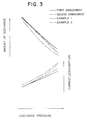
- Fig. 3 is a characteristic view illustrating the relationship between the discharge pressure and the discharge quantity and the relationship between the discharge pressure and the electric current consumption;
- Fig. 4 is a characteristic view illustrating the relationship between the discharge pressure and the pump efficiency;
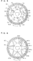
- Figs. 5 and 6 are plan views of an impeller of a Westco-type pump according to a second and a third embodiment of the present invention, respectively; and
- Fig. 7 is a plan view of an impeller of a Westco-type pump according to a comparative example.
- A first embodiment of the present invention which is applied to an automobile fuel feeding pump will be described in connection with Figs. 1 and 2. The fuel feeding pump onto which a filter (not shown) is mounted is used to be disposed in a fuel tank.
- In Fig. 2, the fuel pump 8 comprises a
pump portion 10, amotor portion 12 and adischarge portion 14. Fuel introduced through anintake port 16 of thepump portion 10 passes through amotor chamber 18 of themotor portion 12 and is discharged out of the pump 8 through adischarge port 20 of thedischarge portion 14. - The
motor portion 12 includes apermanent magnet 24 and anarmature 26 which are coaxially accommodated within acylindrical pump case 22. Thepermanent magnet 24 is secured to an inner wall of thepump case 22 and thearmature 26 has adriving shaft 28 rotatably supported by means ofbearings armature 26 and is electrically connected to aterminal 36 secured to anend cover 34. Thisend cover 34 is provided with thedischarge port 20 of thedischarge portion 14. - The
pump portion 10 includes apump housing 44 secured to anopening portion 22a of thepump case 22. Thepump housing 44 has apump cover 38 and apump casing 40. In a disk-like space 46 formed between the inner wall surface 38a of thepump cover 38 and theinner wall surface 40a of thepump casing 40, there is disposed rotatably a disk-like impeller 42. Further, a peripheral portion of thespace 46 is formed into a C-shaped pumping chamber 49 along the periphery of theimpeller 42. Theimpeller 42 is fitted to an end portion of thedriving shaft 28 rotatably supported by thebearings 30 secured to thepump casing 40. Accordingly, theimpeller 42 is axially movable. When theimpeller 42 is rotated integrally with thedriving shaft 28, the fuel introduced from theintake port 16 of thepump cover 38 passes through thepumping chamber 49 into themotor chamber 18 from a discharge port (not shown) of thepump casing 40. - Between the
inner wall surface 40a of thepump casing 40 and oneend surface 42a of theimpeller 42 and between the inner wall surface 38a of thepump cover 38 and theother end surface 42b of theimpeller 42, there arespaces space 54 is defined between a seal surface formed at theinner wall surface 40a of thepump casing 40 and theend surface 42a of theimpeller 42 whereas thespace 55 is defined between a seal surface formed at the inner wall surface 38a of thepump cover 38 and theend surface 42a of theimpeller 42. The seal surfaces are formed in an annular configuration, respectively within an annular area having a radial dimension 1 as shown in Figs. 1 and 2. By rendering thespaces pumping chamber 49. - The
impeller 42 is provided at a part of periphery thereof withvanes 56 andrecesses 58 which alternate with each other as shown in Fig. 1. Theimpeller 42 is provided at a center portion thereof with an axial throughhole 60 designed to be engaged with thedriving shaft 28 and with pressure relief axial throughholes impeller 42. - Furthermore, each
end surface impeller 42 is provided with eight C-shaped grooves each having a U-shaped cross section, which are spaced equiangularly form one another and disposed point-symmetrically about a central of rotation of theimpeller 42. The C-shaped grooves 66 are oriented so that when theimpeller 42 is rotated, the fuel in the U-shaped grooves tends to concentrate at the respective central portion of the C's. The depth of the U-shaped cross section of the C-shaped groove is set to a specific value within a range of 0.01 mm to 0.1 mm. Further, in view of the fact that theend surfaces space shaped grooves 66 are disposed plane-symmetrically with respect to a central surface between theend surfaces impeller 42. All the C-shaped grooves 66 are positioned on the areas of both end surfaces of theimpeller 42 facing the corresponding seal surfaces of thepump cover 38 and thepump casing 40, respectively and then communicated with neither a space accommodating thedriving shaft 28 nor thepumping chamber 49. This prevents fuel from flowing from the shaft accommodating space to thepumping chamber 49 as well as from flowing reversely, thereby preventing the pumping efficiency from deteriorating. Further, thecentral portions 663 of the C-shaped grooves 66 are arranged to substantially coincide with a radial center circle C (indicated by a one dot line in Fig. 1) of the seal surface. - With the impeller being rotated rapidly, the C-shaped grooves are moved at high speed relative to the inner wall 38a of the
pump cover 38 and theinner wall 40a of thepump casing 40. Then, the fuel in the C-shaped grooves is, due to its viscosity, moved in the C-shaped grooves while being attracted to the inner wall 38a and theinner wall 40a, and when it collides against thedownstream side walls 660, the velocity components in the axial direction of theimpeller 42 towards thepump casing 40 are obtained to generate a force axially urging thepump cover 38 or thepump casing 40. Especially, since the fuel inarm portions groove 66 once concentrates at acentral portion 663 and then collides against the downstream side walls to flow towards the seal surfaces, the fuel in thespaces pump cover 38 or thepump casing 40 is generated in the C-shaped grooves formed on the end surfaces 42a and 42b of theimpeller 42, its reaction prevents theimpeller 42 from being pushed to adhere to either thepump cover 38 or thepump casing 40. For this reason, even if thespaces spaces grooves 66 and is forced to intensively flow towards the radial center circle C of the seal surface, a fuel film is formed substantially uniformly between the seal surface and the impeller, thereby enhancing the pumping efficiency even if thespaces - In a second embodiment of the present invention shown in Fig. 5, instead of the C-shaped
grooves 66, V-shapedgrooves 72 are formed on eachend surface impeller 42. The V-shapedgrooves 72 are arranged in a manner such that when theimpeller 42 is rotated, the fuel is moved towards angle portions of the V-shapedgrooves 72. This is alike for the V-shaped grooves on bothend surfaces impeller 42. With these V-shapedgrooves 72, due to the pushing-out effect of the fuel like as in the first embodiment, at both thespace 54 between theimpeller 42 and thepump cover 38 and thespace 55 between theimpeller 42 and thepump casing 40, the adhesion of theimpeller 42 to thepump cover 38 or to thepump casing 40 is prevented. This is because the fuel is pushed out from the V-shapedgrooves 72 towards thepump cover 38 and thepump casing 40. - A third embodiment is shown in Fig. 6, in which a plurality of pairs of
linear grooves end surfaces grooves grooves grooves 84a extend to incline circumferentially outwardly with respect to the direction of rotation of theimpeller 42 while thegrooves 84b extend to incline circumferentially inwardly with respect to the direction of rotation of theimpeller 42. In this manner, the two kinds of thegrooves impeller 42 are formed on bothend surfaces impeller 42 to cause the fuel in thespaces - In this embodiment, since the same pattern of grooves are formed on both
end surfaces impeller 42, it is noted that the impeller is assembled into a structure shown in Fig. 2 without care of which is the right side of the impeller. For this reason, it is possible to realize a structure in which theimpeller 42 is skimmed with certainty with respect to the seal surfaces formed at the inner wall 38a of thepump cover 38 and theinner wall 40a of thepump casing 40, without impairing the assembling workability. - Incidentally, it is possible also in the present invention to alternately arrange the C-shaped grooves and the V-shaped grooves used in the first and the second embodiments so that they may orient opposite to each other with respect to the direction of rotation of the impeller. According this, it is possible to obtain the excellent fuel energizing action by means of the C-shaped grooves and V-shaped grooves while realizing the assembling operation without care of which is the right side of the impeller.
- Also, in the present invention, each C-shaped groove or V-shaped groove may be replaced by a pair of independent grooves arranged corresponding to both arm potions thereof. Further, it may be replaced with a W-shaped groove or the like.
- While in the foregoing embodiments, simple C-shaped or V-shaped grooves are formed on both end surfaces of an impeller to energize the fuel within the
spaces - Next, how the pumping efficiency is excellent in the first and the second embodiment will be apparent from Figs. 3 and 4.
- An explanation will be made on the examples 1 and 2 in comparison with the first and the second embodiments. The example 1 uses an impeller having no groove on either end surface thereof. The example 2 uses an impeller having
spiral grooves 80 formed on bothend surfaces impeller 42. Japanese Unexamined Patent Publication No. 58-24955 and Japanese Unexamined Utility Model Publication No. 57-114195 show the impeller similar to the example 2. The impeller having spiral grooves formed on either end surface thereof can be readily inclined due to slight pressure difference because a fluid unbalance is positively created. - As apparent from Fig. 3, the pumps using impeller according to the first and the second embodiments have relatively large discharge and less current consumption with respect to the discharge pressure, as compared with the pumps using impeller according to the examples 1 and 2.
- Further, as shown in Fig. 4, the pumps using impeller according to the first and the second embodiments have higher pumping efficiencies with respect to the discharge pressure, as compared with the pumps using impeller according to the examples 1 and 2.
- In the first and the second embodiments, it is considered that the reduction in the pumping efficiency is limited due to that the linking is prevented by the effect of the V-shaped grooves or the C-shaped grooves. In comparison, it is found that the example 2 with the spiral grooves causes the pumping efficiency to be reduced as the discharge pressure becomes higher. This is apparently due to that there develops the linking between the impeller and the pump casing or the pump cover to increase the sliding resistance.
- Especially, in the example 2, since the grooves are formed so as to be involuted unidirectionally, it is found that the fuel within the
spaces impeller 42 and the housing, making it liable for theimpeller 42 to incline, hence occurring the linking phenomenon. In comparison, with the impeller according to the first or the second embodiment, the C-shaped grooves or V-shaped grooves tend to concentrate the fuel substantially to the radial center circle C and to push it out. Accordingly, it is seen that a substantially uniform liquid film is maintained within the seal surface to limit the inclination of theimpeller 42 while theimpeller 42 is skimmed with certainty from the inner wall 38a of thepump cover 38 and theinner wall 40a of thepump casing 40, thus making it not liable that the linking phenomenon occurs. In accordance with the present invention, the grooves formed on both end surfaces of an impeller cause fluid to flow towards seal surfaces with a substantially uniform fluid quantity distribution on the impeller. Accordingly, the liquid film is maintained with certainty between both ends of the impeller and the seal surfaces of the housing to reduce the generation of the linking phenomenon. - A disk-shaped impeller (42) having on its periphery a multiple radial vanes (56) and a multiple radial impeller grooves (58) is rotatably disposed in a pump housing. On each end surfaces (42a, 42b) of the impeller (42) there are formed a plurality of C-shaped grooves (66). As the impeller (42) is rotated at a higher speed, the fluid in the C-shaped grooves (66) in the impeller (42) acquires a velocity component in an impeller's axial direction to generate a force sufficient to push a pump cover and a pump casing in the axial direction. Accordingly, since it is avoided for the impeller (42) to adhere either the pump cover or the pump casing, the space between the impeller and the housing inner wall is reduced while the possible leakage of the fluid is reduced.
Claims (20)
- A Westco-type pump for pressurizing a fluid comprising:
a casing (38, 40) having a partial annular pumping chamber (49) connecting an intake port and a discharge port, said casing provided at opposite inner wall surfaces thereof with seal surfaces located radial inward of said pumping chamber; and
an impeller (42) rotatably disposed within said casing and having a plurality of vanes (56) facing said pumping chamber and end surfaces (42a, 42b) apart from said seal surface of said casing by small spaces, characterized in that
said impeller is provided with grooves (66, 72, 84) which are disposed only within a portion of said end surface of said impeller corresponding to said seal surface of said casing, and said grooves extend radially to be inclined with respect to a direction of rotation of said impeller, for concentrating fluid between said end surfaces of said impeller and said seal surfaces of said casing to counter rotation edge portions (660) of said grooves so as to flow towards said seal surfaces, and that said grooves are predetermined such that said fluid concentrations is in a substantially uniform fluid pressure distribution with respect to a radial center circle of said seal surface. - A Westco-type pump according to Claim 1, wherein whole peripheries of said grooves are completely encompassed by said end surface facing said seal surface.
- A Westco-type pump according to Claim 1, wherein each of said grooves has a pair of arm portions inclined opposite with respect to a direction of rotation of said impeller.
- A Westco-type pump according to Claim 3, wherein said counter rotation edge portions of said arm portions are positioned substantially on a radial center circle of said seal surface.
- A Westco-type pump according to Claim 4, wherein said arm portions are connected with each other at said counter rotation edge portions thereof.
- A Westco-type pump according to Claim 3, wherein said counter rotation edge portions of said arm portions are located at a radial inner portion and a radial outer portion of said end surface of said impeller, respectively.
- A Westco-type pump according to Claim 3, wherein said groove is a C-shaped or a V-shaped one.
- A Westco-type pump according to Claim 1, wherein said impeller is disk-shaped and provided at both end surfaces thereof with impeller grooves (58) symmetrically, and said casing is positioned at both sides of said impeller and has said pumping chamber and said seal surface opposite to said both sides of the impeller, and said grooves are formed on the both sides of said impeller.
- An impeller of a Westco-type pump for pressurizing a fluid, said impeller comprising:
a plurality of impeller vanes (56) facing a partial annular pumping chamber (49) defined by a casing; and
end surfaces (42a, 42b) apart from seal surfaces of said casing by small axial spaces, characterized in that
said end surface is provided with grooves (66, 72, 84) which are formed in a portion of said end surface facing said seal surface of said casing, and said grooves extend radially to be inclined with respect to a direction of rotation of said impeller, for concentrating fluid between said end surfaces of said impeller and said seal surfaces of said casing to counter rotation edge portions (660) of said grooves so as to flow towards said seal surfaces, and that said grooves are predetermined such that said fluid concentrations is in a substantially uniform fluid pressure distribution with respect to a radial center circle of said seal surface. - An impeller according to Claim 9, wherein whole peripheries of said grooves are completely encompassed by said end surface facing said seal surface.
- An impeller according to Claim 9, wherein each of said grooves has a pair of arm portions inclined opposite with respect to a direction of rotation of said impeller.
- An impeller according to Claim 11, wherein said counter rotation edge portions of said arm portions are positioned substantially on a radial center circle of said seal surface.
- An impeller according to Claim 12, wherein said arm portions are connected with each other at said counter rotation edge portions thereof.
- An impeller according to Claim 11, wherein said counter rotation edge portions of said arm portions are located at a radial inner portion and a radial outer portion of said end surface of said impeller, respectively.
- An impeller according to Claim 11, wherein said groove is a C-shaped or a V-shaped one.
- An impeller according to Claim 9, wherein said impeller is disk-shaped and provided at both end surfaces thereof with impeller grooves (58) symmetrically, and said casing is positioned at both sides of said impeller and has said pumping chamber and said seal surface opposite to said both sides of the impeller, and said grooves are formed on the both sides of said impeller.
- A fuel pump for feeding fuel to an internal combustion engine including;
a motor portion (12); and
a pump portion (10) integrally assembled with said motor portion (10), said pump portion comprising an impeller rotationally driven by said motor portion and provided at an end surface thereof with a vane train constituted by a plurality of vanes (56) and a plurality of grooves (58) alternately arranged each other, and a casing (40, 38) defining a C-shaped pumping chamber (49) facing said vane train and having seal surface facing said end surface of said impeller through a small axial space, thereby confining the fuel in said pumping chamber, characterized in that
said impeller is provided with grooves (66, 72, 84) which are formed in a portion of said end surface of said impeller facing said seal surface of said casing, and said grooves extend radially to be inclined with respect to a direction of rotation of said impeller, for concentrating fluid between said end surfaces of said impeller and said seal surfaces of said casing to counter rotation edge portions (660) of said grooves so as to flow towards said seal surfaces, and that said grooves are predetermined such that said fluid concentrations is in a substantially uniform fluid pressure distribution with respect to a radial center circle of said seal surface. - A fuel pump according to Claim 17, wherein said impeller is provided at said end surface thereof between said vane train and said grooves with an annular end surface portion facing said seal surface through a small axial space to prevent the fuel from directly flowing into said grooves from said pumping chamber.
- A fuel pump according to Claim 18, wherein each of said grooves has a pair of arm portions (661, 662) inclined opposite with respect to a direction of rotation of said impeller.
- A fuel pump according to Claim 19, wherein said space between said impeller and said casing is smaller than that of a conventional fuel pump.
Applications Claiming Priority (2)
| Application Number | Priority Date | Filing Date | Title |
|---|---|---|---|
| JP07175293A JP3228446B2 (en) | 1993-03-30 | 1993-03-30 | Wesco pump |
| JP71752/93 | 1993-03-30 |
Publications (2)
| Publication Number | Publication Date |
|---|---|
| EP0618367A1 true EP0618367A1 (en) | 1994-10-05 |
| EP0618367B1 EP0618367B1 (en) | 1997-12-03 |
Family
ID=13469583
Family Applications (1)
| Application Number | Title | Priority Date | Filing Date |
|---|---|---|---|
| EP94104508A Expired - Lifetime EP0618367B1 (en) | 1993-03-30 | 1994-03-22 | Westco-type pump |
Country Status (6)
| Country | Link |
|---|---|
| US (1) | US5607283A (en) |
| EP (1) | EP0618367B1 (en) |
| JP (1) | JP3228446B2 (en) |
| KR (1) | KR100231142B1 (en) |
| DE (1) | DE69407080T2 (en) |
| HU (1) | HU222960B1 (en) |
Cited By (3)
| Publication number | Priority date | Publication date | Assignee | Title |
|---|---|---|---|---|
| FR2713712A1 (en) * | 1993-12-07 | 1995-06-16 | Bosch Gmbh Robert | A fuel supply assembly for an internal combustion engine of a motor vehicle from a tank. |
| FR2725407A1 (en) * | 1994-10-07 | 1996-04-12 | Bosch Gmbh Robert | ASSEMBLY FOR TRANSFERRING FUEL FROM AN INTERNAL COMBUSTION TANK OF A MOTOR VEHICLE |
| EP1635067A2 (en) * | 1999-10-28 | 2006-03-15 | Enplas Corporation | Impeller for circumferential current pump and method of forming the same |
Families Citing this family (13)
| Publication number | Priority date | Publication date | Assignee | Title |
|---|---|---|---|---|
| US6019570A (en) * | 1998-01-06 | 2000-02-01 | Walbro Corporation | Pressure balanced fuel pump impeller |
| US6113363A (en) * | 1999-02-17 | 2000-09-05 | Walbro Corporation | Turbine fuel pump |
| US6210102B1 (en) | 1999-10-08 | 2001-04-03 | Visteon Global Technologies, Inc. | Regenerative fuel pump having force-balanced impeller |
| US6299406B1 (en) * | 2000-03-13 | 2001-10-09 | Ford Global Technologies, Inc. | High efficiency and low noise fuel pump impeller |
| DE10160199B4 (en) * | 2001-12-07 | 2005-08-25 | Siemens Ag | Wheel |
| DE10246694B4 (en) * | 2002-10-07 | 2016-02-11 | Continental Automotive Gmbh | Side channel pump |
| DE102006055916A1 (en) * | 2005-11-28 | 2007-07-05 | Aisan Kogyo K.K., Obu | pump |
| US20070177995A1 (en) * | 2006-02-01 | 2007-08-02 | Yoshio Yano | Pump device |
| US20070183908A1 (en) * | 2006-02-06 | 2007-08-09 | Yoshio Yano | Contactless centrifugal pump |
| JP4889432B2 (en) * | 2006-10-06 | 2012-03-07 | 愛三工業株式会社 | Fuel pump |
| KR101007013B1 (en) * | 2008-12-31 | 2011-01-12 | 현담산업 주식회사 | Friction decrease structure of Automobile with Fuel pump |
| KR101011366B1 (en) | 2009-01-07 | 2011-01-28 | 현담산업 주식회사 | Impeller Case structure with Fuel Pump of Automobile |
| CN105782109B (en) * | 2016-03-06 | 2020-05-12 | 亿德机电科技(福建)有限公司 | Special pump vortex impeller for combustor |
Citations (3)
| Publication number | Priority date | Publication date | Assignee | Title |
|---|---|---|---|---|
| US4854830A (en) * | 1987-05-01 | 1989-08-08 | Aisan Kogyo Kabushiki Kaisha | Motor-driven fuel pump |
| EP0450362A1 (en) * | 1990-03-28 | 1991-10-09 | Coltec Industries Inc | Toric pump |
| WO1992011459A1 (en) * | 1990-12-21 | 1992-07-09 | Roy E. Roth Company | Floating self-centering turbine impeller |
Family Cites Families (5)
| Publication number | Priority date | Publication date | Assignee | Title |
|---|---|---|---|---|
| JPS57114195A (en) * | 1980-12-31 | 1982-07-15 | Nippon Musical Instruments Mfg | Electronic musical instrument |
| JPS57171092A (en) * | 1981-04-13 | 1982-10-21 | Nippon Denso Co Ltd | Motor-driven fuel pump |
| JPS582495A (en) * | 1981-06-29 | 1983-01-08 | Matsushita Electric Ind Co Ltd | Voltex flow pump device |
| JPS58197495A (en) * | 1982-05-13 | 1983-11-17 | Nippon Denso Co Ltd | Pump |
| JPS6085284A (en) * | 1983-10-17 | 1985-05-14 | Taiho Kogyo Co Ltd | Rotary oil pump |
-
1993
- 1993-03-30 JP JP07175293A patent/JP3228446B2/en not_active Expired - Fee Related
-
1994
- 1994-03-09 HU HU9400696A patent/HU222960B1/en not_active IP Right Cessation
- 1994-03-22 EP EP94104508A patent/EP0618367B1/en not_active Expired - Lifetime
- 1994-03-22 DE DE69407080T patent/DE69407080T2/en not_active Expired - Lifetime
- 1994-03-30 KR KR1019940006521A patent/KR100231142B1/en not_active IP Right Cessation
-
1995
- 1995-09-08 US US08/525,116 patent/US5607283A/en not_active Expired - Lifetime
Patent Citations (3)
| Publication number | Priority date | Publication date | Assignee | Title |
|---|---|---|---|---|
| US4854830A (en) * | 1987-05-01 | 1989-08-08 | Aisan Kogyo Kabushiki Kaisha | Motor-driven fuel pump |
| EP0450362A1 (en) * | 1990-03-28 | 1991-10-09 | Coltec Industries Inc | Toric pump |
| WO1992011459A1 (en) * | 1990-12-21 | 1992-07-09 | Roy E. Roth Company | Floating self-centering turbine impeller |
Cited By (4)
| Publication number | Priority date | Publication date | Assignee | Title |
|---|---|---|---|---|
| FR2713712A1 (en) * | 1993-12-07 | 1995-06-16 | Bosch Gmbh Robert | A fuel supply assembly for an internal combustion engine of a motor vehicle from a tank. |
| FR2725407A1 (en) * | 1994-10-07 | 1996-04-12 | Bosch Gmbh Robert | ASSEMBLY FOR TRANSFERRING FUEL FROM AN INTERNAL COMBUSTION TANK OF A MOTOR VEHICLE |
| EP1635067A2 (en) * | 1999-10-28 | 2006-03-15 | Enplas Corporation | Impeller for circumferential current pump and method of forming the same |
| EP1635067A3 (en) * | 1999-10-28 | 2006-03-22 | Enplas Corporation | Impeller for circumferential current pump and method of forming the same |
Also Published As
| Publication number | Publication date |
|---|---|
| EP0618367B1 (en) | 1997-12-03 |
| US5607283A (en) | 1997-03-04 |
| HUH3901A (en) | 1999-12-28 |
| JPH06280776A (en) | 1994-10-04 |
| HU9400696D0 (en) | 1994-06-28 |
| KR940021938A (en) | 1994-10-19 |
| HU222960B1 (en) | 2004-01-28 |
| KR100231142B1 (en) | 1999-11-15 |
| DE69407080D1 (en) | 1998-01-15 |
| DE69407080T2 (en) | 1998-04-09 |
| JP3228446B2 (en) | 2001-11-12 |
Similar Documents
| Publication | Publication Date | Title |
|---|---|---|
| US5607283A (en) | Westco-type fuel pump having improved impeller | |
| US4403910A (en) | Pump apparatus | |
| US5527149A (en) | Extended range regenerative pump with modified impeller and/or housing | |
| US4526518A (en) | Fuel pump with magnetic drive | |
| US5642981A (en) | Regenerative pump | |
| US6422808B1 (en) | Regenerative pump having vanes and side channels particularly shaped to direct fluid flow | |
| EP0012544B1 (en) | Liquid ring pump | |
| EP1091127B1 (en) | Regenerative fuel pump having force-balanced impeller | |
| US4478550A (en) | Pump apparatus | |
| US20030118438A1 (en) | Fuel pump | |
| JP3928356B2 (en) | Electric fuel pump | |
| US6540474B2 (en) | Side-channel pump | |
| US6846155B2 (en) | Fuel pump | |
| JP2984582B2 (en) | Friction regeneration pump | |
| JPS6229675Y2 (en) | ||
| US7244094B2 (en) | Low noise impeller pumps | |
| CA1187332A (en) | Fuel pump with magnetic drive | |
| EP1295038B1 (en) | Fuel pumps with reduced contamination effects | |
| JP3052623B2 (en) | Regenerative pump | |
| JP3127973B2 (en) | Operation Noise Reduction Structure of Internal Gear Type Liquid Pump Using Trochoidal Tooth | |
| AU8907591A (en) | Integrated centrifugal pump and motor | |
| EP0787903A2 (en) | Regenerative pump having vanes and side channels particularly shaped to direct fluid flow | |
| JPH0587680B2 (en) | ||
| KR0145236B1 (en) | Regenerative pump | |
| KR200218430Y1 (en) | Impeller Assembly for Magnet Pump |
Legal Events
| Date | Code | Title | Description |
|---|---|---|---|
| PUAI | Public reference made under article 153(3) epc to a published international application that has entered the european phase |
Free format text: ORIGINAL CODE: 0009012 |
|
| AK | Designated contracting states |
Kind code of ref document: A1 Designated state(s): DE FR GB IT |
|
| 17P | Request for examination filed |
Effective date: 19950322 |
|
| 17Q | First examination report despatched |
Effective date: 19960209 |
|
| GRAG | Despatch of communication of intention to grant |
Free format text: ORIGINAL CODE: EPIDOS AGRA |
|
| GRAG | Despatch of communication of intention to grant |
Free format text: ORIGINAL CODE: EPIDOS AGRA |
|
| GRAH | Despatch of communication of intention to grant a patent |
Free format text: ORIGINAL CODE: EPIDOS IGRA |
|
| RAP1 | Party data changed (applicant data changed or rights of an application transferred) |
Owner name: DENSO CORPORATION |
|
| GRAH | Despatch of communication of intention to grant a patent |
Free format text: ORIGINAL CODE: EPIDOS IGRA |
|
| GRAA | (expected) grant |
Free format text: ORIGINAL CODE: 0009210 |
|
| AK | Designated contracting states |
Kind code of ref document: B1 Designated state(s): DE FR GB IT |
|
| REF | Corresponds to: |
Ref document number: 69407080 Country of ref document: DE Date of ref document: 19980115 |
|
| ITF | It: translation for a ep patent filed |
Owner name: SOCIETA' ITALIANA BREVETTI S.P.A. |
|
| ET | Fr: translation filed | ||
| ITPR | It: changes in ownership of a european patent |
Owner name: OFFERTA DI LICENZA AL PUBBLICO;AL PUBBLICO |
|
| REG | Reference to a national code |
Ref country code: GB Ref legal event code: 746 Effective date: 19980916 |
|
| PLBE | No opposition filed within time limit |
Free format text: ORIGINAL CODE: 0009261 |
|
| STAA | Information on the status of an ep patent application or granted ep patent |
Free format text: STATUS: NO OPPOSITION FILED WITHIN TIME LIMIT |
|
| 26N | No opposition filed | ||
| REG | Reference to a national code |
Ref country code: GB Ref legal event code: IF02 |
|
| PGFP | Annual fee paid to national office [announced via postgrant information from national office to epo] |
Ref country code: FR Payment date: 20120319 Year of fee payment: 19 |
|
| PGFP | Annual fee paid to national office [announced via postgrant information from national office to epo] |
Ref country code: GB Payment date: 20120321 Year of fee payment: 19 |
|
| PGFP | Annual fee paid to national office [announced via postgrant information from national office to epo] |
Ref country code: DE Payment date: 20120411 Year of fee payment: 19 |
|
| PGFP | Annual fee paid to national office [announced via postgrant information from national office to epo] |
Ref country code: IT Payment date: 20120321 Year of fee payment: 19 |
|
| GBPC | Gb: european patent ceased through non-payment of renewal fee |
Effective date: 20130322 |
|
| REG | Reference to a national code |
Ref country code: FR Ref legal event code: ST Effective date: 20131129 |
|
| REG | Reference to a national code |
Ref country code: DE Ref legal event code: R119 Ref document number: 69407080 Country of ref document: DE Effective date: 20131001 |
|
| PG25 | Lapsed in a contracting state [announced via postgrant information from national office to epo] |
Ref country code: FR Free format text: LAPSE BECAUSE OF NON-PAYMENT OF DUE FEES Effective date: 20130402 Ref country code: DE Free format text: LAPSE BECAUSE OF NON-PAYMENT OF DUE FEES Effective date: 20131001 Ref country code: GB Free format text: LAPSE BECAUSE OF NON-PAYMENT OF DUE FEES Effective date: 20130322 |
|
| PG25 | Lapsed in a contracting state [announced via postgrant information from national office to epo] |
Ref country code: IT Free format text: LAPSE BECAUSE OF NON-PAYMENT OF DUE FEES Effective date: 20130322 |