EP0617493A1 - Connection device for wire channels - Google Patents
Connection device for wire channels Download PDFInfo
- Publication number
- EP0617493A1 EP0617493A1 EP93119162A EP93119162A EP0617493A1 EP 0617493 A1 EP0617493 A1 EP 0617493A1 EP 93119162 A EP93119162 A EP 93119162A EP 93119162 A EP93119162 A EP 93119162A EP 0617493 A1 EP0617493 A1 EP 0617493A1
- Authority
- EP
- European Patent Office
- Prior art keywords
- strips
- connecting plate
- wires
- threaded shaft
- distance
- Prior art date
- Legal status (The legal status is an assumption and is not a legal conclusion. Google has not performed a legal analysis and makes no representation as to the accuracy of the status listed.)
- Granted
Links
Images


Classifications
-
- H—ELECTRICITY
- H02—GENERATION; CONVERSION OR DISTRIBUTION OF ELECTRIC POWER
- H02G—INSTALLATION OF ELECTRIC CABLES OR LINES, OR OF COMBINED OPTICAL AND ELECTRIC CABLES OR LINES
- H02G3/00—Installations of electric cables or lines or protective tubing therefor in or on buildings, equivalent structures or vehicles
- H02G3/02—Details
- H02G3/06—Joints for connecting lengths of protective tubing or channels, to each other or to casings, e.g. to distribution boxes; Ensuring electrical continuity in the joint
- H02G3/0608—Joints for connecting non cylindrical conduits, e.g. channels
-
- H—ELECTRICITY
- H02—GENERATION; CONVERSION OR DISTRIBUTION OF ELECTRIC POWER
- H02G—INSTALLATION OF ELECTRIC CABLES OR LINES, OR OF COMBINED OPTICAL AND ELECTRIC CABLES OR LINES
- H02G3/00—Installations of electric cables or lines or protective tubing therefor in or on buildings, equivalent structures or vehicles
- H02G3/02—Details
- H02G3/04—Protective tubing or conduits, e.g. cable ladders or cable troughs
- H02G3/0437—Channels
- H02G3/0443—Channels formed by wire or analogous netting
Definitions
- Each mesh cable tray consists of a number of round wires arranged parallel and spaced next to one another, which run uncut along the length of the respective cable tray.
- Transverse connecting wires are provided transversely to these wires lying in the longitudinal direction and are welded to the wires lying in the longitudinal direction at the crossing points.
- the transverse connecting wires are bent in accordance with the cross-sectional profile shape of the mesh cable tray.
- a connecting device known from practice consists of two rails of C-shaped cross section, the transverse dimensions of which are matched to one another so that one rail can be accommodated between the laterally projecting legs of the other rail.
- These rails the length of which is smaller than the distance between the adjacent round wires running in the longitudinal direction of the lattice rings, each have a hole in the center through which a lock screw (pan-head screw with a square socket) passes in the assembled state.
- the rail which is smaller in transverse dimension, is placed with the inserted lock screw in advance onto the channels to be connected to one another.
- the outer rail is then placed from below before a nut can be screwed onto the threaded shaft of the lock screw with the interposition of a washer.
- the square shoulder of the lock screw serves to force the desired distance at the joint between the mesh cable trays on the one hand and to prevent the lock screw from turning when the nut is tightened.
- the distance between the grating channels is inevitably produced by the threaded shaft of the hammer screw, the outer strips ensuring that the anti-rotation device becomes effective when the nut is tightened.
- the side strips on the connecting plate prevent the mesh cable trays from being pushed away to the side by the anti-twist device.
- the new solution does not require the hammer screw to be inserted and the nut to be fitted at the assembly point.
- the connecting plate being a molded sheet metal part, on which two tabs are additionally formed, which ensure the spacing between the mesh trays .
- the bending elements are bent around the wires with a pair of pliers and thus hold the connecting element securely. The tensile forces that occur are always absorbed by the strips of the connecting plate.
- FIG. 1 shows two mesh cable trays 1, 2 to be connected to one another, which are to be connected to one another in use, for which purpose several, preferably at least three, connecting devices 3 are used.
- the connecting device 3 is illustrated in FIG. 1 on an enlarged scale, compared to the mesh cable trays, in order to reveal the essentials.
- the grid channels 1, 2 are identical to one another and consist of a plurality of round wires 4 running in the longitudinal direction and parallel to one another. These round wires 4 are fastened to transverse connecting wires 5, the connecting wires 5 being bent in accordance with the C-shaped channel profile.
- the transverse connecting wires 5 accordingly have a straight section 6 which corresponds to the bottom of the mesh cable tray and which merges into legs 7 projecting upwards at both ends. The legs 7 provide for the production of their side walls in the finished mesh cable tray.
- the transverse connecting wires 6 and the longitudinal wires 4 are each welded to one another at the crossing points.
- each of the mesh cable trays 1, 2 there is in each case a transverse connecting wire 5 directly on the end face, so that the longitudinal wires 4 protrude as little as possible over this transverse connecting wire, on the other hand they are still securely fastened to it.
- the connecting device 3 comprises a C-shaped sheet metal part 8 which has an approximately rectangular connecting plate 9, on the longitudinal edges of which are parallel to one another, two straight strips 11 pointing in the same direction are formed. These strips 11 run parallel to one another and have a spacing, as can be seen from the following functional description.
- connection plate 9 there is also a hole 12 in the center between the two strips 11, which are angled at right angles with respect to the connecting plate 9, through which a threaded shaft 13 leads a hammer screw 14.
- the hammer screw 14 carries, as can be seen from the enlarged representation in Fig. 3, on its threaded shaft 13 a transverse, elongated, narrow and thus hammer-shaped head 15. This is on its underside, i.e. the side facing the threaded shaft 13, with a essentially plan and provide perpendicular contact surface 16 to the longitudinal axis of the threaded shaft 13, which extends on both sides of the threaded shaft 13.
- the head 15 has the shape of an elongated rectangle, delimited by two long edges 17, the short edges 18 extending between the long edges 17 being curved in a convex manner.
- the bearing surface 16 has approximately the shape of an elongated oval, the threaded shaft 13 rising in the middle of this surface thus formed.
- the head 15 has side faces 19 which, starting from the edges 17, initially parallel to each other and then at a distance from the edges 17 towards each other, are curved. Thus, the head 15 has nowhere larger dimensions than is defined by the edges 17.
- the distance between the edges 17 is equal to the nominal diameter of the threaded shaft 13.
- the hammer screw 14 is provided with an anti-rotation device 21 between the threaded shaft 13 and the head 15.
- This anti-rotation device 21 consists of two extensions 22 which are diametrically opposed with respect to the threaded shaft 13 (the other extension 22 is covered by the threaded shaft 13).
- Each of these two extensions 22 is delimited by two flat surfaces 23 and 24, which merge smoothly tangentially into an unthreaded region of the threaded shaft 13 directly adjacent to the head 15 and end there at an imaginary straight line 25, which is a section of a corresponding surface line of the Threaded shaft 13 is.
- the two surfaces 23 and 24 lead away from the threaded shaft 13 in the opposite direction of rotation and merge into one another at an edge 26, which is also parallel to a surface line of the threaded shaft 13.
- the surfaces 23 and 24 form an angle of 90 ° with one another.
- the width of the head 15, measured between the edges 17, is equal to the diameter of the threaded shaft 13, and the flat surface 23 opens tangentially into the threaded shaft 13, the surface 23 also merges smoothly into the side surface 19 of the head 15.
- the side surface 24, however, is perpendicular to the support surface 16.
- the length of the surfaces 23 and 24, measured in the direction parallel to the axis of the threaded shaft 13, is at least half the diameter of the transverse round wires 5, but shorter than their diameter.
- the hammer screw 14 Since the two projections 22 of identical design lie diametrically opposite one another, the hammer screw 14 has an approximately eye-shaped cross section in the area of the anti-rotation device 21.
- the outer contour follows a smooth cylindrical shape up to the diametrically opposite extension which is not visible.
- the connecting device 3 also includes a nut 27 which can be screwed onto the threaded shaft 13 and which is preferably designed as a self-locking nut.
- the handling of the connecting device 3 for connecting the two mesh cable trays 1 and 2 is as follows: First, the connecting devices 3 are prepared by preassembly, in that the threaded shaft 13 is inserted into the bore 12. The threaded shaft 13 is inserted from the side of the strips 11, so that the head 15 of the hammer screw 14 is on the same side of the connecting plate 9 as the strip 11. The nut 27 becomes the end of the threaded shaft 13 protruding from the bore 12 screwed on a little, but at most so far that the free distance between the connecting plate 9 and the bearing surface 16 of the head 15 is even greater than the diameter of the connecting wires 5, which are circular in cross section.
- the grating channels 1 and 2 which are laid on brackets (not shown further), can be connected to one another in a butt joint.
- the head 15 is inserted between the two adjacent connecting wires 5 on the end faces of the two grid channels 1 and 2 and the connecting plate 9 is brought into contact with the corresponding sections of the connecting wires 5 which are aligned with one another.
- the two strips 11 grip laterally, as can be seen in FIG. 2, the connecting wires 5. They prevent the two connecting wires 5 from being able to move further apart than corresponds to the diameter of the threaded shaft 13.
- the anti-rotation device 21 is already located between the connecting wires 5.
- the actuation of the nut 27 in the sense of tightening the hammer screw 14 initially rotates the hammer screw 14 until its anti-rotation device 21 takes effect , ie until the surface 24 of the two extensions 22 abuts the two adjacent connecting wires 5 in the case of a screw with a right-hand thread. This prevents further rotation of the hammer screw 14 about its longitudinal axis, since on the other hand the two connecting wires 5 rest on the adjacent strips 11 and can no longer be pushed away laterally by the extension 22.
- connection device 3 which is attached to the same joint, is operated as described above.
- the hammer-shaped head 15 enables it to be easily inserted into the gap between the adjacent connecting wires 5 on the end face of the two cable trays 1 and 2 when the connecting device 3 is preassembled.
- the head 15 of the hammer screw 14 only needs to be aligned parallel to the connecting wires 5. It can then be pushed between the connecting wires 5 until the connecting plate 9 abuts the connecting wires 5.
- the new connecting device 3 does not require that the individual parts forming the connecting device 3 only have to be assembled one after the other at the joint between the two cable trays 1 and 2. Rather, as can be seen from the above description, the preassembly is possible at any time and it is sufficient to tighten the nut 28 after the connecting device 3 has been plugged in or plugged in. Another tool for holding is not necessary either, because the anti-rotation device 21 prevents the hammer screw 14 from turning undesirably.
- the clear distance between the threaded shaft 13 and the adjacent inside of the respective strip 11 is approximately equal to the diameter of the connecting wires 5.
- the diameter of the threaded shaft 13, determines the distance between the connecting wires 5 of the two mesh cable trays 1 and 2 located on the end face. Consequently is the clear width, measured between the two strips 11, as can be seen from FIG. 2, equal to the overall distance of the two connecting wires 5 measured at this point or in other words equal to the sum of the diameters of the connecting wires 5 plus the diameter of the threaded shaft 13.
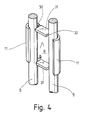
- FIG. 4 Another embodiment of the new connecting device 3 is shown in perspective in FIG. 4.
- the two strips 11, which are integrally formed on the connecting plate 9 have a height relative to the connecting plate 9 which is significantly larger than the diameter of the connecting wires 5 in question.
- there is between the two strips 11 on the other two edges of the connecting plate 9 each formed a tab 31 which rises at right angles above the connecting plate 9 in the same direction as the two strips 11.
- These two tabs 31 serve as spacers and have the task of keeping the two connecting wires 5 at the joint at a distance, as is the case here previously done with the help of the threaded shaft 13.
- the connecting device 3 is plugged onto the front connecting wires 5 of the two grating channels 1 and 2 to be coupled together. Then the two strips 11 and 12, which protrude significantly beyond the connecting wires 5, are bent around with a pair of pliers until the arrangement shown in FIG. 4 is obtained. Since the strips 11 were originally aligned parallel to one another and at right angles to the planar connecting plate 9 over their entire surface, the connecting device 3 could easily be plugged on. After reshaping the 4, the connecting device 3 is secured to the two grid channels 1 and 2.
- the distance between the undeformed strips 11 is dimensioned according to the previous embodiment, i.e. it is equal to twice the diameter of the connecting wire 5 plus the width of the tab 31, measured in the direction of the distance between the two strips 11.
- the two tabs 31, as shown in FIG. 4 expediently have two side edges 32 which run parallel to one another and serve as a contact for the two connecting wires 5.
Abstract
Description
Gitterrinnen dienen dem Verlegen von elektrischen Kabeln, Lichtleiterkabeln, dünnen Rohren und ähnlichem innerhalb von Gebäuden. Jede Gitterrinne besteht aus einer Anzahl von parallel und im Abstand nebeneinander angeordneten Runddrähten, die über die Länge der jeweiligen Kabelrinne ungeschnitten durchlaufen. Quer zu diesen in Längsrichtung liegenden Drähten sind quer verlaufende Verbindungsdrähte vorgesehen, die an den Kreuzungsstellen mit den in Längsrichtung liegenden Drähten verschweißt sind. Die quer verlaufenden Verbindungsdrähte sind entsprechend der Querschnittsprofilgestalt der Gitterrinne gebogen. Jeweils an den Stirnseiten befindet sich je ein quer verlaufender Verbindungsdraht, über den die in Längsrichtung liegenden Drähte möglichst nicht überstehen sollen. Aus fertigungstechnischen Gründen ist dies jedoch nicht immer zu gewährleisten, falls keine aufwendigen Nachbearbeitungen an der Stirnseite der Gitterrinnen vorgenommen werden sollen.Mesh trays are used to lay electrical cables, fiber optic cables, thin pipes and the like within buildings. Each mesh cable tray consists of a number of round wires arranged parallel and spaced next to one another, which run uncut along the length of the respective cable tray. Transverse connecting wires are provided transversely to these wires lying in the longitudinal direction and are welded to the wires lying in the longitudinal direction at the crossing points. The transverse connecting wires are bent in accordance with the cross-sectional profile shape of the mesh cable tray. At each end there is a transverse connecting wire, over which the wires lying in the longitudinal direction should not protrude as far as possible. For manufacturing reasons, however, this cannot always be guaranteed unless extensive post-processing is carried out on the front of the mesh cable trays should be.
Diese Überstände behindern das fluchtende Ausrichten benachbarter Gitterrinnen an der Stoßstelle. Bei der bekannten Verbindungstechnik werden deswegen die Gitterrinnen auf einen kleinen Abstand zueinander gehalten.These protrusions hinder the alignment of adjacent mesh cable trays at the joint. In the known connection technology, the mesh cable trays are therefore kept at a small distance from one another.
Eine aus der Praxis bekannte Verbindungseinrichtung besteht aus zwei im Querschnitt C-förmigen Schienen, deren Querabmessungen so aufeinander abgestimmt sind, daß die eine Schiene zwischen den seitlich aufragenden Schenkeln der anderen Schiene Platz findet. Diese Schienen, deren Länge kleiner ist als der Abstand der benachbarten, in Längsrichtung der Gitterringe verlaufenden Runddrähte, haben mittig jeweils eine Bohrung, durch die im montierten Zustand eine Schloßschraube (Flachrundkopfschraube mit Vierkantansatz) hindurchführt.A connecting device known from practice consists of two rails of C-shaped cross section, the transverse dimensions of which are matched to one another so that one rail can be accommodated between the laterally projecting legs of the other rail. These rails, the length of which is smaller than the distance between the adjacent round wires running in the longitudinal direction of the lattice rings, each have a hole in the center through which a lock screw (pan-head screw with a square socket) passes in the assembled state.
Bei der Montage dieser Verbindungseinrichtung wird von oben her die in der Querabmessung kleinere Schiene mit der eingesteckten Schloßschraube voraus auf die miteinander zu verbindenden Rinnen aufgelegt. Sodann wird von unten her die äußere Schiene aufgesetzt, ehe eine Mutter unter Zwischenlage einer Beilagscheibe auf den Gewindeschaft der Schloßschraube aufgedreht werden kann. Dabei dient der Vierkantansatz der Schloßschraube dazu, einerseits den gewünschten Abstand an der Stoßstelle zwischen den Gitterrinnen zu erzwingen und andererseits ein Mitdrehen der Schloßschraube beim Anziehen der Mutter zu verhindern.When assembling this connecting device, the rail, which is smaller in transverse dimension, is placed with the inserted lock screw in advance onto the channels to be connected to one another. The outer rail is then placed from below before a nut can be screwed onto the threaded shaft of the lock screw with the interposition of a washer. The square shoulder of the lock screw serves to force the desired distance at the joint between the mesh cable trays on the one hand and to prevent the lock screw from turning when the nut is tightened.
Die Montage dieses bekannten Verbindungselementes ist schwierig, wenn man berücksichtigt, daß der Monteur in aller Regel in verhältnismäßog großer Höhe auf einer Leiter arbeiten muß.The assembly of this known connecting element is difficult if one takes into account that the fitter generally has to work on a ladder at a relatively high height.
Ausgehend hiervon ist es Aufgabe der Erfindung, eine Verbindungseinrichtung für Gitterrinnen zu schaffen, die bei der Montage an der Stoßstelle der Gitterrinnen nicht in Einzelteilen zerlegt angebracht werden muß.Proceeding from this, it is an object of the invention to provide a connecting device for mesh cable trays which does not have to be disassembled into individual parts during assembly at the joint of the mesh trays.
Diese Aufgabe wird erfindungsgemäß durch die Verbindungseinrichtung mit den Merkmalen des Anspruches 1 bzw. durch die Verbindungseinrichtung mit den Merkmalen des Anspruches 4 gelöst.This object is achieved according to the invention by the connecting device with the features of
Bei der Ausführungsform nach dem Anspruch 1 wird der Abstand zwischen den Gitterrinnen zwangsläufig durch den Gewindeschaft der Hammerschraube hergestellt, wobei die äußeren Leisten dafür sorgen, daß beim Anziehen der Mutter die Verdrehsicherung wirksam wird. Die seitlichen Leisten an der Verbindungsplatte verhindern ein seitliches Wegdrücken der Gitterrinnen durch die Verdrehsicherung.In the embodiment according to
Infolge des länglichen Kopfes der Hammerschraube ist ohne weiteres eine Vormontage möglich, so daß beim Anbringen des Verbindungselementes an der Stoßstelle nur eine Ausrichtung des Kopfes der Hammerschraube parallel zu den stirnseitigen Drähten der Gitterrinnen erforderlich ist, um den Kopf zwischen die Drähte einzuschieben. Beim nachträglichen Festziehen der Mutter dreht sich die Hammerschraube solange, bis die Verdrehsicherung wirksam wird. Sodann bewirkt eine weitere Verdrehung nur noch, daß der Kopf an die stirnseitigen Drähte der beiden Gitterrinnen herangezogen wird.As a result of the elongated head of the hammer screw, pre-assembly is readily possible, so that when the connecting element is attached to the joint, only an alignment of the head of the hammer screw parallel to the front wires of the mesh cable trays is required to insert the head between the wires. When the nut is subsequently tightened, the hammer screw rotates until the anti-rotation lock takes effect. Then a further twisting only causes the head to be pulled towards the front wires of the two mesh cable trays.
Ein Einstecken der Hammerschraube und ein Aufsetzen der Mutter erst an der Montagestelle ist bei der neuen Lösung nicht erforderlich.The new solution does not require the hammer screw to be inserted and the nut to be fitted at the assembly point.
Anstelle der Hammerschraube, die sowohl den Abstand zwischen den Gitterrinnen herstellt als auch die Verbindungsplatte an den Gitterrinnen sichert, ist auch eine einstückige Lösung möglich, wobei die Verbindungsplatte ein Blechformteil ist, an dem zusätzlich zwei Laschen ausgebildet sind, die den Abstand zwischen den Gitterrinnen gewährleisten. Die Biegeelemente werden nach dem Ansetzen mittels einer Zange um die Drähte herumgebogen und halten so das Verbindungselement sicher fest. Die auftretenden Zugkräfte werden in jedem Falle von den Leisten der Verbindungsplatte aufgenommen.Instead of the hammer screw, which both creates the distance between the mesh cable trays and secures the connecting plate to the mesh trays, a one-piece solution is also possible, the connecting plate being a molded sheet metal part, on which two tabs are additionally formed, which ensure the spacing between the mesh trays . The bending elements are bent around the wires with a pair of pliers and thus hold the connecting element securely. The tensile forces that occur are always absorbed by the strips of the connecting plate.
In der Zeichnung sind Ausführungsbeispiele des Gegenstandes der Erfindung dargestellt. Es zeigen:
- Fig. 1
- zwei miteinander zu verbindende Gitterrinnen sowie ein Verbindungselement in einer perspektivischen Explosionsdarstellung mit jeweils unterschiedlichem Maßstab für das Verbindungselement und die Gitterrinnen,
- Fig. 2
- die Anordnung nach Fig. 1 in einer Draufsicht,
- Fig. 3
- die Hammerschraube der Verbindungseinrichtung nach Fig. 1 in einer vergrößerten Darstellung, in einer Stirnansicht auf den Gewindeschaft und
- Fig. 4
- ein anderes Ausführungsbeispiel des erfindungsgemäßen Verbindungselementes, das durch Biegen zu befestigen ist.
- Fig. 1
- two mesh cable trays to be connected together and a connecting element in a perspective exploded view, each with a different scale for the connecting element and the cable trays,
- Fig. 2
- 1 in a top view,
- Fig. 3
- 1 in an enlarged view, in an end view of the threaded shaft and
- Fig. 4
- another embodiment of the connecting element according to the invention, which is to be fastened by bending.
Fig. 1 zeigt zwei miteinander zu verbindende Gitterrinnen 1, 2, die im Gebrauch auf Stoß miteinander zu verbinden sind, wozu mehrere, vorzugsweise wenigstens drei Verbindungseinrichtungen 3 verwendet werden. Die Verbindungseinrichtung 3 ist in Fig. 1 in einem vergrößerten Maßstab, verglichen mit den Gitterrinnen, veranschaulicht, um das Wesentliche erkennen zu lassen.1 shows two
Die Gitterrinnen 1, 2 sind untereinander gleich ausgebildet und bestehen aus einer Vielzahl von in Längsrichtung durchlaufenden und zueinander parallelen Runddrähten 4. Diese Runddrähte 4 sind an quer verlaufenden Verbindungsdrähten 5 befestigt, wobei die Verbindungsdrähte 5 entsprechend dem C-förmigen Rinnenprofil gebogen sind. Die quer verlaufenden Verbindungsdrähte 5 weisen dementsprechend einen dem Boden der Gitterrinne entsprechenden geraden Abschnitt 6 auf, der beidends in nach oben aufragende Schenkel 7 übergeht. Die Schenkel 7 sorgen bei der fertigen Gitterrinne zur Erzeugung von deren Seitenwänden. Die quer verlaufenden Verbindungsdrähte 6 und die Längsdrähte 4 sind jeweils an den Kreuzungsstellen miteinander verschweißt.The
Bei jeder der Gitterrinnen 1, 2 liegt jeweils ein quer verlaufender Verbindungsdraht 5 unmittelbar an der Stirnseite, so daß die Längsdrähte 4 möglichst wenig über diesen quer verlaufenden Verbindungsdraht überstehen, andererseits an demselben noch sicher zu befestigen sind.In each of the mesh cable trays 1, 2 there is in each case a transverse connecting
Die Verbindungseinrichtung 3 umfaßt ein C-förmig gebogenes Blechteil 8, das eine etwa rechteckige Verbindungsplatte 9 aufweist, an deren parallel zueinander verlaufenden länglichen Kanten zwei in gleicher Richtung weisende gerade Leisten 11 angeformt sind. Diese Leisten 11 verlaufen parallel zueinander und haben einen Abstand, wie er sich aus der nachfolgenden Funktionsbeschreibung ergibt.The connecting
In der Verbindungsplatte 9 ist ferner mittig zwischen den beiden Leisten 11, die gegenüber der Verbindungsplatte 9 rechtwinklig abgewinkelt sind, eine Bohrung 12 enthalten, durch die ein Gewindeschaft 13 einer Hammerschraube 14 führt.In the connecting plate 9 there is also a
Die Hammerschraube 14 trägt, wie dies die vergrößerte Darstellung in Fig. 3 erkennen läßt, auf ihrem Gewindeschaft 13 einen quer verlaufenden, länglichen, schmalen und damit hammerförmigen Kopf 15. Dieser ist an seiner Unterseite, also der dem Gewindeschaft 13 zugekehrten Seite, mit einer im wesentlichen planen und zu der Längsachse des Gewindeschaftes 13 rechtwinkligen Anlagefläche 16 versehen, die sich zu beiden Seiten des Gewindeschaftes 13 erstreckt.The
Der Kopf 15 hat in der Draufsicht auf die Anlagefläche 16 die Gestalt eines länglichen Rechtecks, begrenzt durch zwei lange Kanten 17, wobei die sich zwischen den langen Kanten 17 erstreckenden kurzen Kanten 18 konvex abgerundet gekrümmt sind. Mit anderen Worten, die Auflagefläche 16 hat etwa die Gestalt eines langgestreckten Ovals, wobei in der Mitte dieser so gebildeten Fläche der Gewindeschaft 13 sich erhebt.In the top view of the
Im Anschluß an die Kanten 17 weist der Kopf 15 Seitenflächen 19 auf, die, ausgehend von den Kanten 17, zunächst zueinander parallel und dann im Abstand zu den Kanten 17 aufeinander zu, gekrümmt sind. Somit hat der Kopf 15 an keiner Stelle größere Abmessungen als es durch die Kanten 17 festgelegt ist.Following the
Der Abstand zwischen den Kanten 17 ist gleich dem Nenndurchmesser des Gewindeschaftes 13.The distance between the
Zwischen dem Gewindeschaft 13 und dem Kopf 15 ist die Hammerschraube 14 mit einer Verdrehsicherung 21 versehen. Diese Verdrehsicherung 21 besteht aus zwei Fortsätzen 22, die sich bezüglich des Gewindeschaftes 13 diametral gegenüberliegen (der andere Fortsatz 22 ist durch den Gewindeschaft 13 verdeckt). Jeder dieser beiden Fortsätze 22 ist von zwei ebenen Flächen 23 und 24 begrenzt, die tangential in einen unmittelbar an den Kopf 15 angrenzenden gewindelosen Bereich des Gewindeschaftes 13 glatt übergehen und dort an einer gedachten geraden Linie 25 enden, die ein Ausschnitt aus einer entsprechenden Mantellinie des Gewindeschaftes 13 ist. Die beiden Flächen 23 und 24 führen mit entgegengesetztem Drehsinn von dem Gewindeschaft 13 weg und gehen an einer Kante 26, die ebenfalls parallel zu einer Mantellinie des Gewindeschaftes 13 liegt, ineinander über. Die Flächen 23 und 24 schließen einen Winkel von 90o miteinander ein.The
Da die Breite des Kopfes 15, gemessen zwischen den Kanten 17 gleich dem Durchmesser des Gewindeschaftes 13 ist, und die ebene Fläche 23 tangential in den Gewindeschaft 13 einmündet, geht die Fläche 23 auch glatt in die Seitenfläche 19 des Kopfes 15 über. Die Seitenfläche 24 dagegen steht senkrecht auf der Auflagefläche 16.Since the width of the
Die Länge der Flächen 23 und 24, gemessen in Richtung parallel zu der Achse des Gewindeschaftes 13, ist mindestens halb so groß wie der Durchmesser der quer verlaufenden Runddrähte 5, jedoch kürzer als deren Durchmesser.The length of the
Da sich die beiden gleich gestalteten Fortsätze 22 diametral gegenüberliegen, hat die Hammerschraube 14 im Bereich der Verdrehsicherung 21 einen etwa augenförmigen Querschnitt.Since the two
Zwischen den beiden Fortsätzen 22, also links von der Linie 25 der Fläche 23 und rechts bzw. unterhalb der Linie 25 der Fläche 24, folgt die Außenkontur bis zu dem diametral gegenüberliegenden nicht sicht sichtbaren Fortsatz einer glatten zylindrischen Gestalt.Between the two
Schließlich gehört zu der Verbindungseinrichtung 3 noch eine auf den Gewindeschaft 13 aufschraubbare Mutter 27, die vorzugsweise als selbstsichernde Mutter ausgebildet ist.Finally, the connecting
Die Handhabung der Verbindungseinrichtung 3 zum Verbinden der beiden Gitterrinnen 1 und 2 ist wie folgt:
Zunächst werden die Verbindungseinrichtungen 3 durch Vormontage vorbereitet, indem der Gewindeschaft 13 in die Bohrung 12 eingesteckt wird. Das Einführen des Gewindeschaftes 13 erfolgt von der Seite der Leisten 11 her, so daß sich der Kopf 15 der Hammerschraube 14 auf derselben Seite der Verbindungsplatte 9 befindet wie die Leiste 11. Auf das aus der Bohrung 12 vorstehende Ende des Gewindeschaftes 13 wird die Mutter 27 ein Stück weit aufgeschraubt, höchstens jedoch so weit, daß der freie Abstand zwischen der Verbindungsplatte 9 und der Auflagefläche 16 des Kopfes 15 noch größer ist als der Durchmesser der im Querschnitt kreisrunden Verbindungsdrähte 5.The handling of the connecting
First, the connecting
Nun können mit den so vorbereiteten Verbindungseinrichtungen 3 die auf nicht weiter gezeigten Auslegern verlegten Gitterrinnen 1 und 2 auf Stoß miteinander verbunden werden. Dazu wird der Kopf 15 zwischen die beiden benachbarten Verbindungsdrähte 5 an den Stirnseiten der beiden Gitterrinnen 1 und 2 eingeführt und die Verbindungsplatte 9 zur Anlage an den entsprechenden miteinander fluchtenden Abschnitten der Verbindungsdrähte 5 gebracht. Die beiden Leisten 11 umgreifen dabei seitlich, wie dies Fig. 2 erkennen läßt, die Verbindungsdrähte 5. Sie verhindern, daß die beiden Verbindungsdrähte 5 sich weiter voneinander entfernen können als es dem Durchmesser des Gewindeschaftes 13 entspricht.Now, with the connecting
Wenn bei der Vormontage die Mutter 27 weit genug aufgeschraubt war, befindet sich jetzt bereits die Verdrehsicherung 21 zwischen den Verbindungsdrähten 5. Das Betätigen der Mutter 27 im Sinne eines Festziehens der Hammerschraube 14 dreht zunächst die Hammerschraube 14 solange mit, bis ihre Verdrehsicherung 21 wirksam wird,d.h. bis bei einer Schraube mit Rechtsgewinde die Fläche 24 der beiden Fortsätze 22 an den beiden benachbarten Verbindungsdrähten 5 anstößt. Hierdurch wird ein weiteres Mitdrehen der Hammerschraube 14 um ihre Längeachse verhindert, da andererseits die beiden Verbindungsdrähte 5 an den benachbarten Leisten 11 anliegen und von dem Fortsatz 22 nicht mehr seitlich weggedrängt werden können. Gleichzeitig wird sichergestellt, daß der Kopf 15 quer zu den beiden aneinander zu befestigenden Verbindungsdrähten 5 ausgerichtet ist und mit seiner Anlagefläche 16 diese beiden Verbindungsdrähte 5 zumindest teilweise überdeckt. Ein weiteres Betätigen der Mutter 27 hat deswegen ein Anziehen der Hammerschraube 14 zur Folge, wodurch der Kopf 15 unter Zwischenlage der Verbindungsdrähte 5 gegen die Verbindungsplatte 9 des Blechformteils 8 verspannt wird.If, during the pre-assembly, the
Mit der nächsten Verbindungseinrichtung 3, die an demselben Stoß angebracht wird, wird, wie oben beschrieben, verfahren. Dabei ermöglicht es der hammerförmige Kopf 15, daß er bei vormontierter Verbindungseinrichtung 3 ohne weiteres in den Spalt zwischen den benachbarten Verbindungsdrähten 5 an der Stirnseite der beiden Gitterrinnen 1 und 2 eingeschoben werden kann. Dazu braucht der Kopf 15 der Hammerschraube 14 nur parallel zu den Verbindungsdrähten 5 ausgerichtet zu werden. Er kann sodann zwischen den Verbindungsdrähten 5 durchgeschoben werden, bis die Verbindungsplatte 9 an den Verbindungsdrähten 5 anliegt.The
Die neue Verbindungseinrichtung 3 erfordert es nicht, daß die einzelnen die Verbindungseinrichtung 3 bildenden Teile erst nacheinander an der Stoßstelle zwischen den beiden Gitterrinnen 1 und 2 zusammenmontiert werden müssen. Vielmehr ist, wie sich aus der obigen Beschreibung ergibt, jederzeit die Vormontage möglich und es genügt, nach dem Auf- bzw. Einstecken der Verbindungseinrichtung 3 die Mutter 28 anzuziehen. Ein weiteres Werkzeug zum Gegenhalten ist ebenfalls nicht erforderlich, weil die Verdrehsicherung 21 ein unerwünschtes Mitdrehen der Hammerschraube 14 verhindert.The new connecting
Außerdem ist aus der Funktionsbeschreibung ohne weiteres zu erkennen, daß der lichte Abstand zwischen dem Gewindeschaft 13 und der benachbarten Innenseite der jeweiligen Leiste 11 etwa gleich dem Durchmesser der Verbindungsdrähte 5 ist. Der Durchmesser des Gewindeschaftes 13 legt dagegen fest, welchen Abstand die an der Stirnseite befindlichen Verbindungsdrähte 5 der beiden Gitterrinnen 1 und 2 voneinander haben. Somit ist die lichte Weite, gemessen zwischen den beiden Leisten 11, wie sich aus Fig. 2 ergibt, gleich dem über alles gemesenen Außenabstand der beiden Verbindungsdrähte 5 an dieser Stelle oder mit anderen Worten gleich der Summe der Durchmesser der Verbindungsdrähte 5 zuzüglich dem Durchmesser des Gewindeschaftes 13.In addition, it can be seen from the functional description that the clear distance between the threaded
Ein weiteres Ausführungsbeispiel der neuen Verbindungseinrichtung 3 ist in Fig. 4 perspektivisch gezeigt. Bei diesem Ausführungsbeispiel haben die beiden Leisten 11, die an der Verbindungsplatte 9 angeformt sind, eine Höhe gegenüber der Verbindungsplatte 9, die deutlich größer ist als der Durchmesser der betreffenden Verbindungsdrähte 5. Außerdem ist zwischen den beiden Leisten 11 an den anderen beiden Kanten der Verbindungsplatte 9 jeweils eine Lasche 31 angeformt, die sich rechtwinklig über der Verbindungsplatte 9 in derselben Richtung erhebt wie die beiden Leisten 11. Diese beiden Laschen 31 dienen als Distanzstücke und haben die Aufgabe, die beiden Verbindungsdrähte 5 an der Stoßstelle auf Abstand zu halten, wie dies vorher mit Hilfe des Gewindeschaftes 13 geschehen ist.Another embodiment of the new connecting
Die Handhabung dieser Verbindungseinrichtung 3 nach Fig. 4 geschieht in der Weise, daß auf die stirnseitigen Verbindungsdrähte 5 der beiden miteinander zu kuppelnden Gitterrinnen 1 und 2 die Verbindungseinrichtung 3 aufgesteckt wird. Sodann werden die beiden Leisten 11 und 12, die über die Verbindungsdrähte 5 deutlich überstehen, mit einer Zange herumgebogen, bis sich die in Fig. 4 gezeigte Anordnung ergibt. Da die Leisten 11 ursprünglich über ihre gesamte Fläche zueinander parallel und rechtwinklig zu der ebenen Verbindungsplatte 9 ausgerichtet waren, konnte die Verbindungseinrichtung 3 ohne weiteres aufgesteckt werden. Nach dem Umformen der Leisten 11 entsprechend Fig. 4 ist die Verbindungseinrichtung 3 an den beiden Gitterrinnen 1 und 2 gesichert.4 is handled in such a way that the connecting
Der Abstand zwischen den unverformten Leisten 11 ist entsprechend dem vorhergehenden Ausführungsbeispiel dimensioniert, d.h. er ist gleich dem doppelten Durchmesser des Verbindungsdrahtes 5 zuzüglich der Breite der Lasche 31, gemessen in Richtung des Abstandes zwischen den beiden Leisten 11.The distance between the
Damit möglichst keine zusätzlichen Austreibkräfte entstehen, wenn die beiden Gitterrinnen 1 und 2 aufeinander zugedrückt werden, haben die beiden Laschen 31, wie in Fig. 4 gezeigt, zweckmäßigerweise zwei parallel zueinander verlaufende Seitenkanten 32, die als Anlage für die beiden Verbindungsdrähte 5 dienen.So that there are no additional expulsion forces when the two
Es ist jedoch nicht erforderlich, zwei dieser Laschen 31 zu verwenden, die an den Rändern der Verbindungsplatte 9 sitzen, sondern es ist auch möglich, aus der Mitte der Verbindungsplatte 9 eine einzige Lasche 31 auszuklinken, die sich nach dem Umbiegen etwa in derselben Position befindet wie bei dem vorherigen Ausführungsbeispiel der Gewindeschaft 13.However, it is not necessary to use two of these
Claims (9)
mit einer Verbindungsplatte (9), die zwei zueinander parallele und voneinander beabstandete gerade Leisten (11) trägt, die zusammen mit der Verbindungsplatte (9) ein C-förmiges Profil bilden und mittig zwischen den Leisten (11) eine Öffnung (12) enthält, wobei der lichte Abstand zwischen den Leisten (11) gleich dem über beide Drähte (5) gemessenen Abstand der an dem Stoß benachbarten stirnseitigen Drähte (5) ist,
mit einer Hammerschraube (14), die einen länglichen Kopf (15), einen damit einstückigen Gewindeschaft (13) und eine Verdrehsicherung (21) aufweist, wobei der Gewindeschaft (13) sowie die Verdrehsicherung (21) einen wirksamen Durchmesser haben, der gleich dem Sollabstand der Gitterrinnen (1, 2) an der Stoßstelle ist und bei in der Öffnung (12) eingeführten Gewindeschaft (13) der Kopf (15) auf derselben Seite der Verbindungsplatte (9) liegt wie die Leisten (11), und
mit einer auf den Gewindeschaft aufgeschraubten Mutter (27).Connection device (3) for connecting adjacent mesh cable trays (1, 2), which are arranged in a butt joint at the connection point and have a wire (5) which is bent in accordance with the mesh cable tray profile on their end face adjacent to the butt joint,
with a connecting plate (9), which carries two mutually parallel and spaced straight strips (11), which together with the connecting plate (9) form a C-shaped profile and contains an opening (12) centrally between the strips (11), the clear distance between the strips (11) being equal to the distance, measured over both wires (5), of the end wires (5) adjacent to the joint,
with a hammer screw (14) which has an elongated head (15), a threaded shaft (13) integral therewith and an anti-rotation device (21), the threaded shaft (13) and the anti-rotation device (21) having an effective diameter equal to that The desired spacing of the mesh cable trays (1, 2) is at the joint and, when the threaded shaft (13) is inserted in the opening (12), the head (15) lies on the same side of the connecting plate (9) as the strips (11), and
with a nut (27) screwed onto the threaded shaft.
mit einer aus einem Blechformteil bestehenden Verbindungsplatte (9),
mit einer Anlagefläche für die Drähte (5),
mit zwei zueinander parallelen und voneinander beabstandeten gerade Leisten (11), die zusammen mit der Verbindungsplatte (9) ein C-förmiges Profil bilden und deren lichter Abstand voneinander gleich dem über alles beide Drähte gemessennen Abstand der an dem Stoß benachbarten stirnseitigen Drähte (5) ist,
mit zwei voneinander beabstandete Laschen (31), die mittig zwischen den Leisten (11) angeordnet sind und sich in dieselbe Richtung erstrecken wie die Leisten (11), wobei der freie Abstand zwischen einer Leiste (11) und der benachbarten Kante (32) der Lasche (31) gleich dem Drahtdurchmesser ist und die Breite jeder Lasche (31) gemessen in Richtung parallel zu dem Abstand zwischen den Leisten (11) gleich dem Sollabsabstand zwischen benachbarten Gitterrinnen (1, 2) ist, und
mit Biegeelementen (11), die zum Sichern des Verbindungselementes (3) an den Gitterrinnen (1, 2) um die betreffenden Drähte (5) an der Stoßstelle zumindest teilweise herumbiegbar sind.Connection device (3) for connecting adjacent mesh cable trays (1, 2), which are arranged in a butt joint at the connection point and have a wire (5) which is bent in accordance with the mesh cable tray profile on their end face adjacent to the butt joint,
with a connecting plate (9) consisting of a molded sheet metal part,
with a contact surface for the wires (5),
with two parallel and spaced straight strips (11) which, together with the connecting plate (9), form a C-shaped profile and whose clear distance from one another is equal to the distance of the end wires (5) adjacent to the joint measured over all two wires is
with two spaced apart tabs (31) which are arranged centrally between the strips (11) and extend in the same direction as the strips (11), the free distance between a strip (11) and the adjacent edge (32) of the Tab (31) is equal to the wire diameter and the width of each tab (31) measured in the direction parallel to the distance between the strips (11) is equal to the desired distance between adjacent mesh cable trays (1, 2), and
with bending elements (11) for securing the connecting element (3) on the mesh cable trays (1, 2) around the relevant wires (5) are at least partially bendable at the joint.
Applications Claiming Priority (2)
| Application Number | Priority Date | Filing Date | Title |
|---|---|---|---|
| DE4309862A DE4309862C2 (en) | 1993-03-26 | 1993-03-26 | Connection device for mesh cable trays |
| DE4309862 | 1993-03-26 |
Publications (2)
| Publication Number | Publication Date |
|---|---|
| EP0617493A1 true EP0617493A1 (en) | 1994-09-28 |
| EP0617493B1 EP0617493B1 (en) | 1996-08-28 |
Family
ID=6483934
Family Applications (1)
| Application Number | Title | Priority Date | Filing Date |
|---|---|---|---|
| EP93119162A Expired - Lifetime EP0617493B1 (en) | 1993-03-26 | 1993-11-27 | Connection device for wire channels |
Country Status (2)
| Country | Link |
|---|---|
| EP (1) | EP0617493B1 (en) |
| DE (2) | DE4309862C2 (en) |
Cited By (11)
| Publication number | Priority date | Publication date | Assignee | Title |
|---|---|---|---|---|
| EP0905843A2 (en) * | 1997-09-24 | 1999-03-31 | OBO Bettermann GmbH & Co. KG. | Screwless Fastening device for wire cable trays |
| EP1337019A1 (en) * | 2002-02-18 | 2003-08-20 | Legrand S.p.A. | A connecting clamp, particularly for mesh cable trays with low sides |
| FR2858129A1 (en) * | 2003-07-23 | 2005-01-28 | Const Electr De La Seine Ces | Lattice duct/cable support e.g. cable tray, has successive sections whose ends are connected by splice plate that has flaps which are folded towards each other by including two weft wires pertaining to respective sections |
| WO2006048902A1 (en) * | 2004-11-08 | 2006-05-11 | Legrand S.P.A. | A joining device for cable ducts |
| US7452157B2 (en) * | 2001-02-16 | 2008-11-18 | Icm Group | Connecting butt straps for wire cable trays wire cable trays equipped with same wire cable tray assemblies connected with same |
| EP2280463A2 (en) | 2009-07-27 | 2011-02-02 | CTS Cable Tray Systems SAS | Locking system for cable raceways and cable raceways provided with such a system |
| EP2525457A1 (en) | 2011-05-19 | 2012-11-21 | CTS Cable Tray Systems SAS | Device for attaching a cable-tray section to a bracket, cable tray including such a device and method for assembling the cable tray |
| EP2605350A1 (en) | 2011-12-15 | 2013-06-19 | CTS Cable Tray Systems SAS | System for locking two sections of a cable raceway |
| DE102013224380A1 (en) | 2013-06-20 | 2014-12-24 | Niedax France | Transversal snap-in cable duct section, cable duct with such sections and manufacturing process |
| US9178343B2 (en) | 2010-05-19 | 2015-11-03 | Panduit Corp. | Cable tray cable routing system |
| CN108963909A (en) * | 2018-10-09 | 2018-12-07 | 江苏泰华消防电气设备有限公司 | A kind of bridge lift frame device |
Citations (1)
| Publication number | Priority date | Publication date | Assignee | Title |
|---|---|---|---|---|
| DE2036325A1 (en) * | 1970-07-22 | 1972-01-27 | Bettermann Ohg Neuwalzwerk | Butt joint for cable trays |
-
1993
- 1993-03-26 DE DE4309862A patent/DE4309862C2/en not_active Expired - Lifetime
- 1993-11-27 EP EP93119162A patent/EP0617493B1/en not_active Expired - Lifetime
- 1993-11-27 DE DE59303582T patent/DE59303582D1/en not_active Expired - Fee Related
Patent Citations (1)
| Publication number | Priority date | Publication date | Assignee | Title |
|---|---|---|---|---|
| DE2036325A1 (en) * | 1970-07-22 | 1972-01-27 | Bettermann Ohg Neuwalzwerk | Butt joint for cable trays |
Cited By (16)
| Publication number | Priority date | Publication date | Assignee | Title |
|---|---|---|---|---|
| EP0905843A2 (en) * | 1997-09-24 | 1999-03-31 | OBO Bettermann GmbH & Co. KG. | Screwless Fastening device for wire cable trays |
| EP0905843A3 (en) * | 1997-09-24 | 2000-10-11 | OBO Bettermann GmbH & Co. KG. | Screwless Fastening device for wire cable trays |
| US7452157B2 (en) * | 2001-02-16 | 2008-11-18 | Icm Group | Connecting butt straps for wire cable trays wire cable trays equipped with same wire cable tray assemblies connected with same |
| EP1337019A1 (en) * | 2002-02-18 | 2003-08-20 | Legrand S.p.A. | A connecting clamp, particularly for mesh cable trays with low sides |
| FR2858129A1 (en) * | 2003-07-23 | 2005-01-28 | Const Electr De La Seine Ces | Lattice duct/cable support e.g. cable tray, has successive sections whose ends are connected by splice plate that has flaps which are folded towards each other by including two weft wires pertaining to respective sections |
| WO2006048902A1 (en) * | 2004-11-08 | 2006-05-11 | Legrand S.P.A. | A joining device for cable ducts |
| EP2280463A2 (en) | 2009-07-27 | 2011-02-02 | CTS Cable Tray Systems SAS | Locking system for cable raceways and cable raceways provided with such a system |
| US9853428B2 (en) | 2010-05-19 | 2017-12-26 | Panduit Corp. | Cable tray cable routing system |
| US9178343B2 (en) | 2010-05-19 | 2015-11-03 | Panduit Corp. | Cable tray cable routing system |
| US11056865B2 (en) | 2010-05-19 | 2021-07-06 | Panduit Corp. | Cable tray cable routing system |
| EP2525457A1 (en) | 2011-05-19 | 2012-11-21 | CTS Cable Tray Systems SAS | Device for attaching a cable-tray section to a bracket, cable tray including such a device and method for assembling the cable tray |
| EP2605350A1 (en) | 2011-12-15 | 2013-06-19 | CTS Cable Tray Systems SAS | System for locking two sections of a cable raceway |
| DE102013224380A1 (en) | 2013-06-20 | 2014-12-24 | Niedax France | Transversal snap-in cable duct section, cable duct with such sections and manufacturing process |
| EP2816687A1 (en) | 2013-06-20 | 2014-12-24 | Niedax France | Cable-tray section with transverse locking, cable tray comprising such sections and method for manufacturing same |
| CN108963909A (en) * | 2018-10-09 | 2018-12-07 | 江苏泰华消防电气设备有限公司 | A kind of bridge lift frame device |
| CN108963909B (en) * | 2018-10-09 | 2024-03-29 | 江苏泰华消防电气设备有限公司 | Bridge frame hanging device |
Also Published As
| Publication number | Publication date |
|---|---|
| DE4309862A1 (en) | 1994-09-29 |
| EP0617493B1 (en) | 1996-08-28 |
| DE59303582D1 (en) | 1996-10-02 |
| DE4309862C2 (en) | 1997-08-14 |
Similar Documents
| Publication | Publication Date | Title |
|---|---|---|
| DE2730980C3 (en) | Anchoring device for electrical connectors | |
| EP0617493B1 (en) | Connection device for wire channels | |
| DE3025660C2 (en) | Fastening device | |
| DE2543897B2 (en) | Device for holding a tubular handrail | |
| DE69919189T2 (en) | TOY KIT | |
| DE10009978A1 (en) | Arrangement for fixing vehicle antenna has can be placed in position with protrusions in opening; protrusions are engaged behind opening by turning device | |
| DE3340341C2 (en) | ||
| DE2916003A1 (en) | Fixing device connecting two building components - has threaded rod held by one unit while another prevents motion of fixer in rail | |
| DE102018206849B4 (en) | Device for clamping fastening | |
| DE2636434C3 (en) | Frame corner connection | |
| EP0628734A1 (en) | Fastening device for removably connecting a polygonal tube, particularly a tube with a rectangular profile | |
| DE1575092B1 (en) | Threaded nut can be clamped to plates | |
| DE3308568A1 (en) | CABLE TERMINAL | |
| EP0704931B1 (en) | Clamping device for connecting cables to bars | |
| DE3718089C2 (en) | ||
| DE8500148U1 (en) | Device for equipotential bonding for earth conductors in electrical installations | |
| DE3941097C1 (en) | Cable channel or tray support - has coupling element fixable from above in form of shaft fitting selectable slots and with projection to act like hook | |
| DE102022125081B3 (en) | Floor support of a cable support system | |
| EP2885557A1 (en) | Clamp for connecting ropes | |
| DE3941095C1 (en) | Cable channel or tray support - has coupling element operable from above in form of self-tapping screw fitting selectable slots | |
| DE3509997C2 (en) | ||
| DE2849840C2 (en) | U-nut made of spring steel sheet | |
| EP0088311B1 (en) | Clamping device for a construction element, especially a screw | |
| DE2243848C3 (en) | Fastening arrangement for electrical installation devices | |
| DE2501003A1 (en) | Electrical connector with paddle shaped tubular blades - has ring shaped strips separated by gap bridged by contact blades with curved sides (SW310576) |
Legal Events
| Date | Code | Title | Description |
|---|---|---|---|
| PUAI | Public reference made under article 153(3) epc to a published international application that has entered the european phase |
Free format text: ORIGINAL CODE: 0009012 |
|
| AK | Designated contracting states |
Kind code of ref document: A1 Designated state(s): BE CH DE FR LI NL |
|
| 17P | Request for examination filed |
Effective date: 19950228 |
|
| 17Q | First examination report despatched |
Effective date: 19951027 |
|
| GRAH | Despatch of communication of intention to grant a patent |
Free format text: ORIGINAL CODE: EPIDOS IGRA |
|
| GRAH | Despatch of communication of intention to grant a patent |
Free format text: ORIGINAL CODE: EPIDOS IGRA |
|
| GRAA | (expected) grant |
Free format text: ORIGINAL CODE: 0009210 |
|
| AK | Designated contracting states |
Kind code of ref document: B1 Designated state(s): BE CH DE FR LI NL |
|
| PG25 | Lapsed in a contracting state [announced via postgrant information from national office to epo] |
Ref country code: NL Free format text: LAPSE BECAUSE OF FAILURE TO SUBMIT A TRANSLATION OF THE DESCRIPTION OR TO PAY THE FEE WITHIN THE PRESCRIBED TIME-LIMIT Effective date: 19960828 |
|
| ET | Fr: translation filed | ||
| REF | Corresponds to: |
Ref document number: 59303582 Country of ref document: DE Date of ref document: 19961002 |
|
| PG25 | Lapsed in a contracting state [announced via postgrant information from national office to epo] |
Ref country code: BE Effective date: 19961130 |
|
| NLV1 | Nl: lapsed or annulled due to failure to fulfill the requirements of art. 29p and 29m of the patents act | ||
| PLBE | No opposition filed within time limit |
Free format text: ORIGINAL CODE: 0009261 |
|
| STAA | Information on the status of an ep patent application or granted ep patent |
Free format text: STATUS: NO OPPOSITION FILED WITHIN TIME LIMIT |
|
| REG | Reference to a national code |
Ref country code: CH Ref legal event code: PL |
|
| 26N | No opposition filed | ||
| REG | Reference to a national code |
Ref country code: CH Ref legal event code: AEN Free format text: DAS PATENT WURDE AUFGRUND DES WEITERBEHANDLUNGSANTRAGS VOM 31.07.97 REAKTIVIERT. |
|
| REG | Reference to a national code |
Ref country code: CH Ref legal event code: NV Representative=s name: KIRKER & CIE SA |
|
| PGFP | Annual fee paid to national office [announced via postgrant information from national office to epo] |
Ref country code: CH Payment date: 20021017 Year of fee payment: 10 |
|
| PGFP | Annual fee paid to national office [announced via postgrant information from national office to epo] |
Ref country code: FR Payment date: 20021104 Year of fee payment: 10 |
|
| PG25 | Lapsed in a contracting state [announced via postgrant information from national office to epo] |
Ref country code: LI Free format text: LAPSE BECAUSE OF NON-PAYMENT OF DUE FEES Effective date: 20031130 Ref country code: CH Free format text: LAPSE BECAUSE OF NON-PAYMENT OF DUE FEES Effective date: 20031130 |
|
| REG | Reference to a national code |
Ref country code: CH Ref legal event code: PL |
|
| PG25 | Lapsed in a contracting state [announced via postgrant information from national office to epo] |
Ref country code: FR Free format text: LAPSE BECAUSE OF NON-PAYMENT OF DUE FEES Effective date: 20040730 |
|
| REG | Reference to a national code |
Ref country code: FR Ref legal event code: ST |
|
| PGFP | Annual fee paid to national office [announced via postgrant information from national office to epo] |
Ref country code: DE Payment date: 20081130 Year of fee payment: 16 |
|
| PG25 | Lapsed in a contracting state [announced via postgrant information from national office to epo] |
Ref country code: DE Free format text: LAPSE BECAUSE OF NON-PAYMENT OF DUE FEES Effective date: 20100601 |