EP0617272B1 - norrichtung zur Porositätsmessung eines Filterelementes - Google Patents
norrichtung zur Porositätsmessung eines Filterelementes Download PDFInfo
- Publication number
- EP0617272B1 EP0617272B1 EP94400359A EP94400359A EP0617272B1 EP 0617272 B1 EP0617272 B1 EP 0617272B1 EP 94400359 A EP94400359 A EP 94400359A EP 94400359 A EP94400359 A EP 94400359A EP 0617272 B1 EP0617272 B1 EP 0617272B1
- Authority
- EP
- European Patent Office
- Prior art keywords
- filter
- encapsulation
- filter element
- membrane
- tubular
- Prior art date
- Legal status (The legal status is an assumption and is not a legal conclusion. Google has not performed a legal analysis and makes no representation as to the accuracy of the status listed.)
- Expired - Lifetime
Links
- 239000012528 membrane Substances 0.000 claims description 37
- 238000005259 measurement Methods 0.000 claims description 33
- 238000005538 encapsulation Methods 0.000 claims description 30
- 210000005070 sphincter Anatomy 0.000 claims description 16
- 239000012530 fluid Substances 0.000 claims description 9
- 238000002347 injection Methods 0.000 claims description 2
- 239000007924 injection Substances 0.000 claims description 2
- 238000007789 sealing Methods 0.000 claims description 2
- 230000003068 static effect Effects 0.000 claims description 2
- 238000013523 data management Methods 0.000 claims 1
- 238000005253 cladding Methods 0.000 description 8
- 235000019504 cigarettes Nutrition 0.000 description 6
- 238000004891 communication Methods 0.000 description 5
- 125000006850 spacer group Chemical group 0.000 description 5
- 208000031968 Cadaver Diseases 0.000 description 3
- 238000009826 distribution Methods 0.000 description 3
- 238000009434 installation Methods 0.000 description 3
- 238000006073 displacement reaction Methods 0.000 description 2
- 230000000694 effects Effects 0.000 description 2
- 239000011229 interlayer Substances 0.000 description 2
- 238000004519 manufacturing process Methods 0.000 description 2
- 238000000034 method Methods 0.000 description 2
- 238000012545 processing Methods 0.000 description 2
- 238000013022 venting Methods 0.000 description 2
- 241000287107 Passer Species 0.000 description 1
- 240000008042 Zea mays Species 0.000 description 1
- 230000000295 complement effect Effects 0.000 description 1
- 230000005484 gravity Effects 0.000 description 1
- 238000011084 recovery Methods 0.000 description 1
- 230000000717 retained effect Effects 0.000 description 1
- 238000003860 storage Methods 0.000 description 1
- 230000007704 transition Effects 0.000 description 1
- 238000013519 translation Methods 0.000 description 1
Images

Classifications
-
- G—PHYSICS
- G01—MEASURING; TESTING
- G01N—INVESTIGATING OR ANALYSING MATERIALS BY DETERMINING THEIR CHEMICAL OR PHYSICAL PROPERTIES
- G01N15/00—Investigating characteristics of particles; Investigating permeability, pore-volume or surface-area of porous materials
- G01N15/08—Investigating permeability, pore-volume, or surface area of porous materials
-
- A—HUMAN NECESSITIES
- A24—TOBACCO; CIGARS; CIGARETTES; SIMULATED SMOKING DEVICES; SMOKERS' REQUISITES
- A24C—MACHINES FOR MAKING CIGARS OR CIGARETTES
- A24C5/00—Making cigarettes; Making tipping materials for, or attaching filters or mouthpieces to, cigars or cigarettes
- A24C5/32—Separating, ordering, counting or examining cigarettes; Regulating the feeding of tobacco according to rod or cigarette condition
- A24C5/34—Examining cigarettes or the rod, e.g. for regulating the feeding of tobacco; Removing defective cigarettes
- A24C5/3418—Examining cigarettes or the rod, e.g. for regulating the feeding of tobacco; Removing defective cigarettes by pneumatic means
-
- G—PHYSICS
- G01—MEASURING; TESTING
- G01N—INVESTIGATING OR ANALYSING MATERIALS BY DETERMINING THEIR CHEMICAL OR PHYSICAL PROPERTIES
- G01N15/00—Investigating characteristics of particles; Investigating permeability, pore-volume or surface-area of porous materials
- G01N15/08—Investigating permeability, pore-volume, or surface area of porous materials
- G01N2015/084—Testing filters
Definitions
- the present invention relates to a device for measurement of the porosity of a filter element in the form of a rod or a stick substantially cylindrical shape.
- the section delimited by the membrane at rest is provided substantially equal to that of the filter you want measure, and slightly lower than that of the element tubular.
- the tubular membrane deploys so like a sphincter under the effect of its own elasticity to apply and "encapsulate" the filtered.
- the porosity or draft of the filter can then be determined by placing one of the orifices under vacuum of the tubular member, while the other is set to the open air and for example by measuring constant flow pressure of the air sucked through the filtered.
- the setting of the encapsulation length which can be carried out continuously, is not feasible only in control mode only.
- the positioning of the tubular sleeve in function of the filter length is hardly automatable: It requires a relatively tube displacement and measurement displacement of the latter.
- this device is necessarily bulky in height: To measure a filter encapsulated on the maximum length, the tube must come completely out of the tubular membrane, thereby increasing the total height of the measuring head.
- the object of the invention is therefore more particularly to remove these drawbacks.
- this device offers a device for measuring the porosity of a filter element, this device making intervene means of encapsulation of the element of filter acting like a sphincter, means allowing to generate an air flow through the filter element, once the filter element encapsulated, and means for measuring at least a parameter relating to the flow of fluid passing through the filter element.
- Such a device is for example disclosed in document EP-A-0 007 836.
- this device is characterized in that that the encapsulation means comprise a succession encapsulation modules arranged coaxially end to end butt and each acting like a sphincter, independently of the others, thanks to control means distinct from those of others.
- transition from one to the other of the two states can be done by admitting a fluid under pressure or, on the contrary, by creating a depression in the volume insert, return to the first position taking place thanks to the elasticity of the membrane.
- the means encapsulation include a single body whose wall internal is doubled by a succession of sections of membrane connected end to end to each other, from watertight, thanks to a multiplicity of spacers elastic annulars in tight contact with said body, so as to constitute a succession of volumes dividers each delimited by the internal wall of the body, a section of membrane and two spacers successive annulars, each of these volumes being connected to a control circuit separate from that of the others.
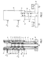
- the measuring head comprises a tubular body 1 substantially cylindrical with the interior of which are arranged end to end, a plurality of sections of tubular membrane 2, 3, 4, 5, coaxial, tightly connected to each other thanks to annular spacers 6, 7, 8, 9, 10 fixed tightly on the body 1. Sealing spacer / membrane / body is produced here using O-rings.
- spacers 6 to 10 delimit with the sections of membrane and body, intermediate chambers 11, 12, 13, 14 communicating with a distributor 15 associated with the body 1, by means of radial holes 16, 17, 18, 19.
- the dispenser consists of a drawer formed by a cylindrical tubular sleeve 20, slidably mounted on the body 1, by means of three seals 21, 22, 23 axially offset so as to delimit two annular chambers 24 , 25 one of which is connected to a permanent suction circuit (arrow F 1 ) while the other is connected to a control circuit (arrow F 2 ) capable of generating suction, or venting , or even an injection of pressurized fluid.
- the lower membrane section 5 or basic sphincter has a height equal to the shortest length of filtered. It is in the retracted state, following a suction in chamber 14 to allow the introduction of the filter rod and its ejection. he goes into the deployed state (venting or under chamber pressure) to ensure the encapsulation of the filter during the draft measurement process.
- the upper membrane sections 2, 3 and 4 are intended to be kept retracted, by suction permanent in rooms 11, 12, 13 or ordered simultaneously with the basic sphincter 5, depending on the length of the filter stick.
- the distance axially separating the two seals 22, 23 is slightly greater than the distance between holes 16 and 19 so that that in the high position of the sleeve 20, the four holes 16, 17, 18, 19 lead into room 25.
- the position bottom of sleeve 20 is such that only hole 19 is in communication with room 25.
- the distance between the seals 21, 22 is, in turn, designed so as to that in the lower position of the section, the holes 16, 17 and 18 lead to room 24.
- the membrane sections 5, 4, 3, 2 may have lengths of 80 mm respectively, 20 mm, 20 mm and 16 mm, for sticks of filters which can have lengths of 80 mm, 100 mm, 120 mm and 136 mm.
- the tubular element 20 will be placed in the lower position of so that only the hole 19 is in communication with chamber 25 and so only the basic sphincter 5 is brought into the deployed position during the measurement.
- the element tubular will be placed in an intermediate position so that holes 17, 18 and 19 are in communication with room 25 and thus the sections membrane 5, 4, 3 can move into the deployed position during the measurement.
- the sleeve tubular 20 will be brought up so that that all the holes 16 to 19 are in communication with chamber 25 and so that membranes 2 to 5 are controlled in synchronization.
- a strip 30 having corresponding notches 32 at each measurement position is fixed on the base 31 which supports the body 1.
- the tubular sleeve 20 includes a lug 33 which can engage in each of these notches 32 so as to be retained in the desired axial position for the measure envisaged.
- the position of the tubular sleeve 20 is adjusted ensured by rotation around its main axis of a sufficient value to release the lug 33 from the notch 32 in which it was inserted then, after a translation in the desired direction, repositioning of lug 33 in the notch corresponding to the desired setting with a new rotation in the opposite direction of the sleeve 20.
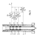
- the encapsulation head could be associated with a distribution circuit controlled by solenoid valves, such as that shown in Figure 3.
- the holes 16, 17, 18, 19 produced in the body 1 are connected to four respective solenoid valves EV 1 to EV 4 whose direct outputs S 1 are connected to a permanent suction circuit 34.
- the bypass outputs S 2 of the solenoid valves EV 1 to EV 3 are connected to the input of the solenoid valve EV 4 .
- the bypass outlet S 2 of the latter opens, for its part, outside (to the atmosphere) or even into a circuit for admitting pressurized fluid.
- the solenoid valves SV 1 to SV 4 are controlled so as to occupy the position which they occupy in FIG. 3, in which the input E is connected to the direct output S 1 , of so that the intermediate chambers 11 to 14 are subjected to permanent suction.
- the membrane sections 5 to 2 are therefore in the retracted position and therefore offer a passage section greater than the section of the filter rod.
- the encapsulation will then be carried out by switching at least the solenoid valve EV 4 and, depending on the length of the stick, one or more of the following solenoid valves EV 3 , EV 2 , EV 1 .
- the inputs E of the switched solenoid valves are connected to their bypass output S 2 and therefore to the bypass circuit 35 which is vented (or to the possible circuit of pressurized fluid) by the output S 2 of the EV 4 solenoid valve.
- the ejection phase is obtained by bringing the electrovalves EV 1 to EV 4 to their initial state so as to cause the retraction of the sections of membrane 2 to 5.
- the stick which has just been tested can then be removed, for example by letting it descend by gravity.
- An important advantage of the device described above is that it allows the determination the porosity of the cladding, for example in paper, filter sticks.
- the air flow passing through the filter will be identical to that noted during the TFE measurement.
- the TPE measurement will be different from the TFE measurement in because of the air flow sucked which penetrates laterally at inside the filter, through the cladding.
- the gap between the two measurements is therefore representative of the cladding porosity.
- FIG. 4 The installation shown in FIG. 4 involves an encapsulation head of the type of that shown in FIG. 3 and with which is associated a distribution circuit comprising four control electrovalves EV 1 to EV 4 .
- This additional sphincter 36 and of this shutter 37 is ensured by a control circuit involving two respective solenoid valves EV 5 and EV 6 of the type of solenoid valves EV 1 to EV 4 .
- the direct output of the EV 5 solenoid valve is connected to the suction circuit 34, while its bypass output S 2 is connected to a pressurized fluid circuit 39.
- the suction chamber 38 is in communication thanks to a hole, with a draft measurement circuit 40, being understood that, by definition, the drawing of a filter cigarette is the pressure drop measured at one end of it, when it is crossed axially by a normalized flow of 17.5 ml / s, the other end being the atmosphere, the envelope of the filter or cladding being made airtight by an envelope encapsulation over its entire length. This measure is called TFE (Fully Encapsulated Filter Draw).
- the measurement circuit 40 therefore comprises a conduit 41 equipped with a pressure sensor differential 42 with analog output, and connected to a static vacuum generating member 43 via a specially calibrated critical flow orifice 44 of so as to precisely obtain a flow rate of 17.5 ml / s.
- the vacuum generator 43 used in this example is of the venturi type which, supplied by a flow of compressed air controlled by an EV 7 solenoid valve, makes it possible to generate a suction.
- the entire device is controlled by a microcomputer 46 which performs the tasks of controlling the solenoid valves EV 1 to EV 7 as a function of the measurement cycle and which manages the data.
- This system performs data processing, tasks display (display 50) of the TPE and TFE values, the comparison of these values with respect to the minimum and maximum, the triggering of alarms, either by display, either by sound means and calculation at the end of the batch statistics necessary for managing the production.
- a complete measurement cycle may include successively a phase of introduction of the filter, a TPE measurement phase, a TFE measurement phase and a phase ejection.
- the membrane sections 2 to 5 are brought to the retracted state so as to leave the filter passage, while the retaining sphincter 36 is arranged in the deployed state.
- Shutter 37 is then in the open position.
- the shutter 37 is placed in the closed position, to seal the suction chamber 38, and the basic sphincter 5 is deployed position to perform an encapsulation partial filter.
- the membrane sections 2 to 4 are kept in the retracted state.
- the microcomputer 46 then performs the entry of the TPE value detected by sensor 42.
- the TFE measurement phase can then be performed by bringing to the deployed state all or part of the sections of membrane 4, 3, 2, depending on the length of the filter, and this, in order to achieve complete encapsulation of the filter.
- the microcomputer 46 then enters the TFE values detected by sensor 42 then performs a processing of these values, their display, the triggering of an alarm if necessary, and storage results.
- the ejection phase includes a stop of the suction in the measurement circuit 41, the return of membrane sections 2 to 5 and 36 in the retracted state, as well as shutter 37 in the open state and recovery filter below the body 1.
Landscapes
- Chemical & Material Sciences (AREA)
- Dispersion Chemistry (AREA)
- Physics & Mathematics (AREA)
- Health & Medical Sciences (AREA)
- Life Sciences & Earth Sciences (AREA)
- Analytical Chemistry (AREA)
- Biochemistry (AREA)
- General Health & Medical Sciences (AREA)
- General Physics & Mathematics (AREA)
- Immunology (AREA)
- Pathology (AREA)
- Cigarettes, Filters, And Manufacturing Of Filters (AREA)
- Sampling And Sample Adjustment (AREA)
Claims (12)
- Vorrichtung zur Bestimmung der Porosität eines Filterelementes, wobei diese Vorrichtung wie ein Sphinkter wirkende Mittel zur Einkapselung des Filterelementes, Mittel zur Erzeugung eines Luftdurchsatzes durch das Filterelement, sobald das Filterelement eingekapselt ist, und Mittel zur Bestimmung wenigstens eines Parameters bezüglich des Flüssigkeitsstroms, der das Filterelement durchquert, verwendet, dadurch gekennzeichnet, daß die Einkapselungsmittel eine Reihe von Einkapselungsmodulen (2 bis 5) umfassen, die in dichter Folge koaxial angeordnet sind und durch jeweils von den anderen verschiedene Steuermittel unabhängig voneinander wie ein Sphinkter wirken.
- Vorrichtung nach Anspruch 1, dadurch gekennzeichnet, daß die Anzahl der verwendeten Einkapselungsmodule (2 bis 5) von der Länge des Filterelementes abhängt, so daß Filter mit unterschiedlicher Länge eingekapselt werden können.
- Vorrichtung nach einem der Ansprüche 1 und 2, dadurch gekennzeichnet, daß die Einkapselungsmodule (2 bis 5) ein röhrenförmiges Bauteil (1) verwenden, dessen zylindrische Innenwand mit einer röhrenförmigen, elastischen Membran verstärkt ist, die zusammen mit der erwähnten Wand ein Zwischenraumvolumen (11 bis 14) definiert, dessen Druck durch einen Steuerkreis so modifiziert werden kann, daß die Membran die folgenden zwei Zustände annehmen kann:einen zur Wand hin zurückgezogenen Zustand, wobei sie einen Abschnitt mit maximalem Durchlaß bietet,einen zur Mitte des Bauteils (1) hin gerichteten Zustand, in welchem sie einen Abschnitt mit verringertem Durchlaß bietet, so daß sie an einem Filterelement, das eingesetzt wird, wenn sie sich im zurückgezogenen Zustand befindet, zur Anlage kommen und dieses teilweise einkapseln kann.
- Vorrichtung nach Anspruch 3, dadurch gekennzeichnet, daß der Übergang von einem Zustand in den anderen durch Einlaß einer unter Druck stehenden Flüssigkeit in das Innere des Zwischenraumvolumens (11 bis 14) oder im umgekehrten Fall durch Erzeugen eines Unterdrucks innerhalb des Volumens erfolgt.
- Vorrichtung nach einem der vorhergehenden Ansprüche, dadurch gekennzeichnet, daß das erwähnte röhrenförmige Bauteil (1) allen Einkapselungsmodulen (2 bis 5) gemeinsam ist.
- Vorrichtung nach Anspruch 5, dadurch gekennzeichnet, daß die elastischen, röhrenförmigen Membranen der verschiedenen Einkapselungsmodule (2 bis 5) eng aneinander angeordnet und dank einer Vielzahl ringförmiger Dichtungen (6 bis 10), die in engem Kontakt mit dem erwähnten Bauteil sind, in dichter Weise verbunden sind, so daß sie eine Reihe von Zwischenraumvolumina (11 bis 14) bilden, die jeweils durch die Innenwand des Bauteils (1), einen Membranabschnitt und zwei aufeinanderfolgende, ringförmige Dichtungen begrenzt sind, wobei jedes dieser Volumina (11 bis 14) mit einem Steuerkreis (16 bis 19) verbunden ist, die sich von denjenigen der anderen unterscheidet.
- Vorrichtung nach Anspruch 6, dadurch gekennzeichnet, daß die Zwischenraumvolumina mit einem Verteiler (15) kommunizieren, der auf dem Bauteil mittels entsprechender, radial angeordneter Bohrungen (16 bis 19) montiert ist.
- Vorrichtung nach Anspruch 7, dadurch gekennzeichnet, daß der Verteiler aus einem Einschub besteht, der durch ein zylindrisches, röhrenförmiges Element (20) gebildet wird, das durch drei Abdichtungen (21, 22, 23) gleitend auf dem Bauteil (1) montiert ist, die axial so versetzt sind, daß sie zwei ringförmige Kammern (24, 25) begrenzen, wobei eine davon mit einem permanenten Ansaugkreis verbunden ist, während die andere mit einem Steuerkreis verbunden ist, der das Ansaugen, die Entlüftung oder sogar das Einspritzen einer unter Druck stehenden Flüssigkeit bewirken kann.
- Vorrichtung nach einem der vorhergehenden Ansprüche, dadurch gekennzeichnet, daß die erwähnten Einkapselungsmittel zusätzlich, neben einem Basismodul zur Einkapselung (5), nacheinander umfassen:einen elastischen Membranabschnitt (36), der einen zusätzlichen, als Anschlag für das Filterstäbchen bei seiner Einführung dienenden Sphinkter bildet,einen Stopfen (37), der von einer offenen Stellung zu einer geschlossenen Stellung wechseln kann, um das Bauteil (1) hermetisch zu verschließen, indem er in dessen Innerem eine Ansaugkammer begrenzt.
- Vorrichtung nach Anspruch 9, dadurch gekennzeichnet, daß die Ansaugkammer mit einem Meßkreis (40) verbunden ist, der einen Ansaugkreis (41) umfaßt, welcher mit einem Druckfühler (42) ausgestattet und mittels einer Öffnung mit kritischem Durchsatz (44) mit einem Organ zur Erzeugung eines Unterdrucks (43) verbunden ist.
- Vorrichtung nach Anspruch 10, dadurch gekennzeichnet, daß der Unterdruckgenerator (43) eine Venturidüse ist und über ein Elektroventil mit einem kontrollierten Luftstrom gespeist wird.
- Vorrichtung nach einem der Ansprüche 9 und 10, dadurch gekennzeichnet, daß die Erfassung der von dem Meßfühler (42) gemessenen Werte durch einen Mikrocomputer erfolgt, der die Steuerbefehle der Vorrichtung gewährleistet und die Daten verwaltet.
Applications Claiming Priority (2)
| Application Number | Priority Date | Filing Date | Title |
|---|---|---|---|
| FR9303799A FR2703157B1 (fr) | 1993-03-26 | 1993-03-26 | Dispositif pour la mesure de la porosité d'un élément de filtre. |
| FR9303799 | 1993-03-26 |
Publications (2)
| Publication Number | Publication Date |
|---|---|
| EP0617272A1 EP0617272A1 (de) | 1994-09-28 |
| EP0617272B1 true EP0617272B1 (de) | 1998-06-03 |
Family
ID=9445603
Family Applications (1)
| Application Number | Title | Priority Date | Filing Date |
|---|---|---|---|
| EP94400359A Expired - Lifetime EP0617272B1 (de) | 1993-03-26 | 1994-02-18 | norrichtung zur Porositätsmessung eines Filterelementes |
Country Status (5)
| Country | Link |
|---|---|
| US (1) | US5428987A (de) |
| EP (1) | EP0617272B1 (de) |
| JP (1) | JP3328417B2 (de) |
| DE (2) | DE617272T1 (de) |
| FR (1) | FR2703157B1 (de) |
Families Citing this family (9)
| Publication number | Priority date | Publication date | Assignee | Title |
|---|---|---|---|---|
| US5719328A (en) * | 1996-06-25 | 1998-02-17 | Hoechst Celanese Corporation | Pressure drop tester for filter rods |
| CN1208614C (zh) * | 1998-07-22 | 2005-06-29 | 日本烟草产业株式会社 | 透气性测定装置 |
| GB2397486B (en) * | 2003-01-24 | 2005-07-13 | Molins Plc | Improved measuring device |
| US20060272659A1 (en) * | 2005-06-06 | 2006-12-07 | Gerd Kobal | Modular smoking article and method of use |
| US7614279B2 (en) * | 2006-10-10 | 2009-11-10 | Porous Materials, Inc. | Determination of pore structure characteristics of filtration cartridges as a function of cartridge length |
| US8272252B2 (en) * | 2006-10-10 | 2012-09-25 | Porous Materials, Inc. | Pore structure characterization of filtration cartridges at specific locations along cartridge length |
| DE102012102337A1 (de) | 2012-03-20 | 2013-10-10 | Hauni Maschinenbau Ag | Messanordnung, ausgebildet und eingerichtet zum Messen von in Strangeinheiten der Tabak verarbeitenden Industrie hergestellten Strängen und/oder Strangabschnitten sowie Strangeinheit mit einer solchen Messanordnung und Verfahren zum Messen |
| CA2892733A1 (en) | 2013-02-13 | 2014-08-21 | Philip Morris Products S.A. | Evaluating porosity distribution within a porous rod |
| CN110702572B (zh) * | 2019-09-29 | 2022-09-02 | 郑琼 | 一种土壤入渗自动补水和测量装置 |
Family Cites Families (5)
| Publication number | Priority date | Publication date | Assignee | Title |
|---|---|---|---|---|
| US4069704A (en) * | 1976-05-25 | 1978-01-24 | Celanese Corporation | Variable length encapsulating pressure drop tester |
| DE2813315A1 (de) * | 1978-03-28 | 1979-10-11 | Hauni Werke Koerber & Co Kg | Vorrichtung zum pruefen des zugwiderstandes von stabfoermigen artikeln der tabakverarbeitenden industrie |
| EP0007836B1 (de) * | 1978-07-13 | 1981-07-29 | Service D'exploitation Industrielle Des Tabacs Et Des Allumettes | Vorrichtung zum Messen des Zuges von Rauchartikeln, wie Zigaretten, und Apparat zum kombinierten Messen mit so einer Vorrichtung |
| US4627448A (en) * | 1985-02-25 | 1986-12-09 | Kamm Roger D | Tobacco smoke article holder and method therefor |
| JPH0737932B2 (ja) * | 1987-04-16 | 1995-04-26 | 日本たばこ産業株式会社 | ベンチレ−シヨン測定器における検体支持装置 |
-
1993
- 1993-03-26 FR FR9303799A patent/FR2703157B1/fr not_active Expired - Fee Related
-
1994
- 1994-02-18 DE DE0617272T patent/DE617272T1/de active Pending
- 1994-02-18 EP EP94400359A patent/EP0617272B1/de not_active Expired - Lifetime
- 1994-02-18 DE DE69410670T patent/DE69410670T2/de not_active Expired - Fee Related
- 1994-03-24 US US08/216,993 patent/US5428987A/en not_active Expired - Fee Related
- 1994-03-28 JP JP05696594A patent/JP3328417B2/ja not_active Expired - Fee Related
Also Published As
| Publication number | Publication date |
|---|---|
| US5428987A (en) | 1995-07-04 |
| FR2703157A1 (fr) | 1994-09-30 |
| JPH06300676A (ja) | 1994-10-28 |
| DE69410670T2 (de) | 1999-02-04 |
| DE617272T1 (de) | 1995-05-18 |
| EP0617272A1 (de) | 1994-09-28 |
| FR2703157B1 (fr) | 1995-06-09 |
| DE69410670D1 (de) | 1998-07-09 |
| JP3328417B2 (ja) | 2002-09-24 |
Similar Documents
| Publication | Publication Date | Title |
|---|---|---|
| EP0062549B1 (de) | Vorrichtung zum Filtern von Fluiden und in dieser Vorrichtung durchgeführtes Verfahren | |
| WO2021052872A1 (fr) | Pipe à eau portative | |
| CA2888635C (fr) | Dispositif de preparation de boisson par infusion de dosette avec berceau pivotant | |
| FR2703157A1 (fr) | Dispositif pour la mesure de la porosité d'un élément de filtre. | |
| EP0261021A1 (de) | Druckmittelbehälter mit Anwesenheitsgeber für Flüssigkeit in einer Gaskammer | |
| WO2001053449A1 (fr) | Dispositif de culture cellulaire et tissulaire a circulation perfectionnee de fluide de culture | |
| EP0337842B1 (de) | Verfahren und Vorrichtung zum Messen der Elastizität einer oberflächlichen Schicht, insbesondere der Haut | |
| EP0031981A2 (de) | Verfahren zur Herstellung einer Raumballonhülle, hergestellte Hülle und deren Verwendung in der Raumfahrt | |
| WO1989000308A1 (fr) | Regulateur de pression | |
| WO2013182608A1 (fr) | Dispositif portatif de gonflage d'un pneu de velo, notamment un pneu tubeless | |
| FR2702563A1 (fr) | Dispositif pour le prélèvement d'échantillons de sols. | |
| EP0434535A1 (de) | Vorrichtung zur elektrischen Isolierung die ein Leitungselement bildet und Anlage mit einer solchen Vorrichtung | |
| EP0052862A1 (de) | Einrichtung zum Sterilisieren einer Flüssigkeit | |
| EP0974402A1 (de) | Pumpe mit einem Kugelrückschlagventil | |
| EP1573305B1 (de) | Probenträger zur messung des zuges und der feuchte von porösen objekten | |
| EP0974401A1 (de) | Pumpe mit Belüftungseinrichtung | |
| EP0151377A1 (de) | Vorrichtung zum Füllen von Zigarettenpapierhülsen | |
| EP0807822B1 (de) | Messung eines aus einer Oberfläche austretenden Gasstromes | |
| WO1993016365A1 (fr) | Procede et dispositif pour prelever un echantillon d'eau a une profondeur determinee | |
| WO2007132128A1 (fr) | Appareil régulateur et débitmètre de gaz à détente et à clapet d'obturation de la voie d'écoulement du gaz | |
| EP0419309A1 (de) | Vorrichtung zur Entnahme einer Fluidprobe aus einem Bohrloch | |
| CH618590A5 (de) | ||
| FR2597595A3 (fr) | Dispositif pour detecter le niveau d'un liquide dans un reservoir | |
| EP0032088A2 (de) | Vorrichtung zum Trennen von Flüssigkeit und Dampf aus einem Fluid-Strom und Dampferzeuger mit solchen Vorrichtungen | |
| EP0655402A1 (de) | Tangentialer Abscheider |
Legal Events
| Date | Code | Title | Description |
|---|---|---|---|
| PUAI | Public reference made under article 153(3) epc to a published international application that has entered the european phase |
Free format text: ORIGINAL CODE: 0009012 |
|
| 17P | Request for examination filed |
Effective date: 19940302 |
|
| AK | Designated contracting states |
Kind code of ref document: A1 Designated state(s): DE FR GB |
|
| GBC | Gb: translation of claims filed (gb section 78(7)/1977) | ||
| DET | De: translation of patent claims | ||
| 17Q | First examination report despatched |
Effective date: 19961203 |
|
| GRAG | Despatch of communication of intention to grant |
Free format text: ORIGINAL CODE: EPIDOS AGRA |
|
| GRAG | Despatch of communication of intention to grant |
Free format text: ORIGINAL CODE: EPIDOS AGRA |
|
| GRAH | Despatch of communication of intention to grant a patent |
Free format text: ORIGINAL CODE: EPIDOS IGRA |
|
| GRAH | Despatch of communication of intention to grant a patent |
Free format text: ORIGINAL CODE: EPIDOS IGRA |
|
| GRAA | (expected) grant |
Free format text: ORIGINAL CODE: 0009210 |
|
| AK | Designated contracting states |
Kind code of ref document: B1 Designated state(s): DE FR GB |
|
| GBT | Gb: translation of ep patent filed (gb section 77(6)(a)/1977) |
Effective date: 19980603 |
|
| REF | Corresponds to: |
Ref document number: 69410670 Country of ref document: DE Date of ref document: 19980709 |
|
| PLBE | No opposition filed within time limit |
Free format text: ORIGINAL CODE: 0009261 |
|
| STAA | Information on the status of an ep patent application or granted ep patent |
Free format text: STATUS: NO OPPOSITION FILED WITHIN TIME LIMIT |
|
| 26N | No opposition filed | ||
| REG | Reference to a national code |
Ref country code: GB Ref legal event code: IF02 |
|
| PGFP | Annual fee paid to national office [announced via postgrant information from national office to epo] |
Ref country code: FR Payment date: 20081210 Year of fee payment: 16 |
|
| PGFP | Annual fee paid to national office [announced via postgrant information from national office to epo] |
Ref country code: GB Payment date: 20090209 Year of fee payment: 16 |
|
| PGFP | Annual fee paid to national office [announced via postgrant information from national office to epo] |
Ref country code: DE Payment date: 20090423 Year of fee payment: 16 |
|
| GBPC | Gb: european patent ceased through non-payment of renewal fee |
Effective date: 20100218 |
|
| REG | Reference to a national code |
Ref country code: FR Ref legal event code: ST Effective date: 20101029 |
|
| PG25 | Lapsed in a contracting state [announced via postgrant information from national office to epo] |
Ref country code: FR Free format text: LAPSE BECAUSE OF NON-PAYMENT OF DUE FEES Effective date: 20100301 |
|
| PG25 | Lapsed in a contracting state [announced via postgrant information from national office to epo] |
Ref country code: DE Free format text: LAPSE BECAUSE OF NON-PAYMENT OF DUE FEES Effective date: 20100901 |
|
| PG25 | Lapsed in a contracting state [announced via postgrant information from national office to epo] |
Ref country code: GB Free format text: LAPSE BECAUSE OF NON-PAYMENT OF DUE FEES Effective date: 20100218 |