EP0616392A2 - Matable connector - Google Patents
Matable connector Download PDFInfo
- Publication number
- EP0616392A2 EP0616392A2 EP94103424A EP94103424A EP0616392A2 EP 0616392 A2 EP0616392 A2 EP 0616392A2 EP 94103424 A EP94103424 A EP 94103424A EP 94103424 A EP94103424 A EP 94103424A EP 0616392 A2 EP0616392 A2 EP 0616392A2
- Authority
- EP
- European Patent Office
- Prior art keywords
- connector
- fitting
- pin
- connector housing
- housing
- Prior art date
- Legal status (The legal status is an assumption and is not a legal conclusion. Google has not performed a legal analysis and makes no representation as to the accuracy of the status listed.)
- Granted
Links
Images


Classifications
-
- H—ELECTRICITY
- H01—ELECTRIC ELEMENTS
- H01R—ELECTRICALLY-CONDUCTIVE CONNECTIONS; STRUCTURAL ASSOCIATIONS OF A PLURALITY OF MUTUALLY-INSULATED ELECTRICAL CONNECTING ELEMENTS; COUPLING DEVICES; CURRENT COLLECTORS
- H01R13/00—Details of coupling devices of the kinds covered by groups H01R12/70 or H01R24/00 - H01R33/00
- H01R13/64—Means for preventing incorrect coupling
- H01R13/641—Means for preventing incorrect coupling by indicating incorrect coupling; by indicating correct or full engagement
-
- H—ELECTRICITY
- H01—ELECTRIC ELEMENTS
- H01R—ELECTRICALLY-CONDUCTIVE CONNECTIONS; STRUCTURAL ASSOCIATIONS OF A PLURALITY OF MUTUALLY-INSULATED ELECTRICAL CONNECTING ELEMENTS; COUPLING DEVICES; CURRENT COLLECTORS
- H01R13/00—Details of coupling devices of the kinds covered by groups H01R12/70 or H01R24/00 - H01R33/00
- H01R13/62—Means for facilitating engagement or disengagement of coupling parts or for holding them in engagement
- H01R13/621—Bolt, set screw or screw clamp
- H01R13/6215—Bolt, set screw or screw clamp using one or more bolts
Definitions
- This invention relates to a connector in which two connector housings are fitted together, and more particularly to a connector in which a fitting-completed condition of the two connector housings can be detected by a fitting indicator such as a detection pin or electrical detector.
- the bolt tightening operation is carried out using a tool such as an impact wrench. If the bolt is tightened excessively, the bolt may be broken, or the housing may be damaged. Therefore, in recent years, there has been proposed a construction in which a threaded portion of a bolt is provided partially on a distal end portion of a bolt shaft, and in a fitting-completed condition of two connector housings, the threaded portion of the bolt extends forwardly from the nut, thereby freely rotating without engagement with the nut. This prevents excessive tightening of the bolt (for example, Japanese Patent Unexamined Publication No. 63-13283).
- the present invention has been made under the above circumstances, and an object of the invention is to provide a connector in which a fitted condition of two connector housings can be easily perceived.
- the present invention provides a connector wherein a bolt is provided on one connector housing and a nut is provided on the other connector housing. By tightening the bolt relative to the nut, the two connector housings are displaced relative to each other in a connecting direction and fitted together.
- An indicator is provided on the connector housing, the indicator being displaced in accordance with the displacement of the two connector housings in the connection direction to indicate a fitting-completed condition of the two connector housing.
- the indicator when the bolt is tightened relative to the nut, the indicator is displaced in accordance with the displacement of the two connector housings in the connecting direction and indicates the fitting-completed condition of the two connector housings. Therefore, by viewing the indicator, the operator can readily know the fitting-completed condition of the two connector housings. Therefore, the operator effects the bolt tightening operation while viewing the indicator, and by doing so, the bolt tightening operation can be stopped in a suitable condition in which the tightening of the bolt is not excessive or insufficient.
- a second embodiment achieves the above object by the provision of a pin insertion hole formed in one connector housing, the hole having opposite open ends; a fitting detection pin having a resilient, inwardly-deformable insertion piece at a distal end thereof, insertable into the pin insertion hole from one end of the pin insertion hole; and a projection portion formed on the other connector housing, insertable into the pin insertion hole from the other end thereof in accordance with the displacement of the two connector housings in a connecting direction.
- the projection portion retains the fitting detection pin at a distal end thereof to urge the pin toward the one end of the pin insertion hole.
- the insertion piece is gradually, resiliently deformed inward.
- the fitting detection pin In a fitting-uncompleted condition of the two connector housings, the fitting detection pin is prevented (by retainment by the projection portion) from being further inserted, and in a fitting-completed condition of the two connector housings, the amount of deformation of the insertion piece is large so that the retainment thereof by the projection portion is released. Therefore, the fitting detection pin can be inserted to a position beyond the distal end of the projection portion.
- the present invention according to a fourth embodiment provides a pressing portion provided on the one connector housing; a pressure sensitive element provided on the other connecting housing and pressed by the pressing portion in a fitting-completed condition of the two connector housings; and fitting detection connection terminals provided on the other connector housing for outputting a signal from the pressure sensitive element.
- the present invention according to a fifth embodiment provides a pair of conductors provided on the connector housing and electrically connected together in a fitting-completed condition of the two connector housings; and fitting detection connection terminals provided on the connector housing for detecting whether or not electrical connection between the conductors is made.
- the pressing portion provided on the one connector housing presses the pressure sensitive element provided on the other connector housing, so that the output of the pressure sensitive element is changed. Therefore, by connecting a detection circuit to the fitting detection connection terminals to output a signal from the pressure sensitive element, the fitting-completed condition can be detected.
- the pair of conductors provided on the connector housing are electrically connected together. Therefore, by connecting the detection circuit to the fitting detection connection terminals, the fitting-completed condition of the two connector housings can be detected.
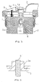
- FIGS. 1 and 2 show a condition before two connector housings 1 and 2 are fitted together
- Figs. 3 and 4 show a fitting-completed condition of the two connector housings 1 and 2.
- a female connector housing 1 is in the form of a rectangular block as a whole and has a number of female terminals (not shown) provided therein. An upper surface portion of female connector housing 1 is covered with a cover 3 made, for example, of rubber.
- a bolt insertion hole 1a is formed through a central portion of the female connector housing 1 in a vertical direction, and a bolt 4 is received in the bolt insertion hole 1a.
- a threaded portion 4a is formed only on a distal end portion of a shaft of the bolt 4, and a bolt head 4b is projected from the upper surface of the female connector housing 1.
- the bolt 4 is rotatable relative to the female connector housing 1 and is supplied with a moving force in a direction (vertical direction in the drawings) of forward and backward threaded movement.
- the male connector housing 2 has a tubular hood portion 2b of a square shape with an open top.
- the hood portion is formed on an upper portion of a base 2a, which is of a rectangular shape.
- the hood portion 2b has such a size that the female connector housing 1 can be fitted therein.
- a number of male terminals (not shown), corresponding respectively to the previously-mentioned female terminals, are provided within the male connector housing 2 and are supported on the base 2a.
- a nut 6 for threaded engagement with the bolt 4 is provided integrally within the boss 5, for example, by insert molding.
- a bar-like projection portion 7 is provided in the male connector housing 2 at a left portion thereof (in the drawings), and extends upward from the base 2a.
- This projection portion 7 extends generally to a level of an upper surface of the hood portion 2b.
- An insertion hole 8 corresponding to the projection portion 7 is formed through the female connector housing 1 and extends in the vertical direction.
- This insertion hole 8 has a stepped configuration such that its upper end portion is slightly larger in diameter than its lower portion.
- a detection pin 9, which is elongated in the vertical direction and functions as an indicator, is inserted into this upper end portion of a larger diameter from the upper side.
- the lower end of the detection pin 9 is retained by a stepped portion of the insertion hole 8, so that its downward movement is limited. As shown in Fig. 2, this detection pin is inserted into a boss 3a, formed on the cover 3, from the lower side. An upper surface of the boss 3a is formed in a thin portion 3b that can be easily broken. Preferably, the detection pin 9 has a bright color different from that of the cover 3.
- the two connector housings 1 and 2 are fitted together in the following manner.
- the female connector housing 1 is lightly fitted in the male connector housing from the upper side, so that the threaded portion 4a of bolt 4 can be threaded into nut 6.
- the upper end portion of the projection portion 7 is slightly inserted into the insertion hole 8.
- the operator tightens the bolt 4 relative to the nut 6, using a tool such as an impact wrench.
- a tool such as an impact wrench.
- the two connector housings 1 and 2 are displaced relative to each other in the connecting direction and are fitted together, as previously described.
- the projection portion 7 moves upward within the insertion hole 8 relative thereto and pushes the lower end of the detection pin 9 upwardly.
- the upper end portion of the detection pin 9 pierces the thin portion 3b of the cover 3, projecting upward from the upper surface and is exposed to the exterior.
- the tightening operation can be completed in a suitable manner, that is, in the fitting-completed condition of the two connector housings 1 and 2, in which the bolt 4 is not excessively or insufficiently tightened.
- the detection pin 9 indicates the fitting-completed condition in accordance with the displacement of the two connector housings 1 and 2 in the connecting direction during the tightening of the bolt 4.
- the two connector housings 1 and 2 can be positively brought into the fitting-completed condition.
- the thin portion 3b is formed on the cover 3, and the detection pin 9 pierces this thin portion 3b to project from the upper surface.
- the detection pin 9 is urged and displaced by the projection portion 7 to pierce the thin portion 3b of the cover 3; however, the shape of the indicator, as well as the structure for displacing the indicator, can be modified, and the invention is not meant to be limited.
- a viewing window may be provided on the connector housing so that the displacement of the indicator can be displayed, or the indicator may be swingingly displaced to indicate the fitting-completed condition.
- the bolt may be provided on the male connector housing while the nut is provided on the female connector housing.
- the threaded portion of the bolt can extend forward from the nut to freely rotate in the fitting-completed condition of the two connector housings.
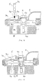
- a connector of the invention according to a second embodiment is shown in Figs. 5-10 and includes a female connector housing 1 in the form of a rectangular block as a whole and has a number of female terminals (not shown) provided therein.
- a cover 3 made, for example, of rubber is attached to an upper surface of the female connector housing 1 by a cover holder 3a.
- a bolt insertion hole 1a is formed through a central portion of the female connector housing 1 in a vertical direction, and a bolt 4 is received in the bolt insertion hole 1a.
- a threaded portion 4a is formed only on a distal end portion of a shaft of the bolt 4, and a bolt head 4b is projected from the upper surface of the female connector housing 1.
- the bolt 4 is rotatable relative to the female connector housing 1 and is supplied with a moving force in a direction (vertical direction in the drawings) by forward and backward threaded movement.
- the male connector housing 2 has a tubular hood portion 2b of a square shape with an open top, which hood portion is formed on an upper portion of a base 2a of a rectangular shape.
- the hood portion 2b has such a size that the female connector housing 1 can be fitted therein.
- a number of male terminals (not shown), corresponding respectively to the previously-mentioned female terminals, are provided within the male connector housing 2 and are supported on the base 2a.
- a boss 5 is provided at a central portion of the male connector housing 2, and is projected upwardly from and formed integrally with the base 2a.
- a nut 6 for threaded engagement with the bolt 4 is provided integrally within the boss 5, for example, by insert molding.
- a pin insertion hole 8' for the insertion of a fitting detection pin 9' (later described) thereinto is formed in a left portion (in the drawings) of the female connector housing 1 and extends therethrough in a vertical direction.
- the pin insertion hole 8' has a smaller-diameter portion 8a at its upper end portion, a tapered portion 8b, which extends from this smaller-diameter portion to an intermediate portion and increases in diameter progressively downwardly.
- a lower half portion of a larger diameter extends to a lower end of the hole without changing its diameter.
- An insertion port 10 is formed in the cover 3 and the cover holder 3a and is disposed in registry with the upper end portion of the pin insertion hole 8'.
- the male connector housing 2 has a projection portion 7' in the form of a cylindrical boss that is projected upwardly from the base 2a, and is disposed in registry with the pin insertion hole 8'.
- An insertion hole 7a is formed through the projection portion 7' in a vertical direction.
- the fitting detection pin 9' is made, for example, of a plastics material and has integral insertion pieces 9a and 9a provided at a distal end portion of a shaft thereof corresponding in diameter to the smaller-diameter portion 8a of the pin insertion hole 8' and the insertion port 10, the insertion pieces 9a and 9a being expansible into a bifurcated configuration in a downward direction.
- a head 9b of an enlarged diameter is formed on the upper end of the fitting detection pin 9'.
- the insertion pieces 9a and 9a are expanded outwardly away from each other when an external force acts on them, and the insertion pieces can be resiliently deformed inwardly, that is, in a direction to narrow the expansion, by an external force.
- the fitting detection pin 9' is beforehand received at its distal end portion in the pin insertion hole 8' of the female connector housing.
- the insertion pieces 9a and 9a are joined together into a smaller dimension as shown in Fig. 9, and in this condition, the fitting detection pin is inserted into the pin insertion hole 8' through the insertion port 10.
- the insertion pieces 9a and 9a are expanded into an angle corresponding to that of the tapered portion 8b of the pin insertion hole 8', with the head 9b placed on the upper surface of the insertion port 10.
- the female connector housing 1 having the fitting detection pin 9' beforehand attached thereto as described above, is lightly fitted into the male connector housing 2 from the upper side, so that the threaded portion 4a of the bolt 4 can now be threaded into the nut 6.
- the operator tightens the bolt 4 relative to the nut 6 using a tool such as an impact wrench.
- a tool such as an impact wrench.
- the two connector housings 1 and 2 are displaced relative to each other in a connecting direction and are fitted together as described above.
- the projection portion 7' is inserted into the pin insertion hole 8' from the lower side and moves upward as the two connector housings 1 and 2 are displaced in the connecting direction.
- the two connector housings 1 and 2 are fitted together to a certain degree, and in this half-fitted condition, the distal end (that portion around the insertion hole 7a) of the projection portion 7' retains the insertion pieces 9a and 9a to urge the fitting detection pin 9' upwardly as shown in Figs. 5 and 6, so that the fitting detection pin 9' is pushed back upwardly.
- the fitting detection pin 9' can be inserted to a position beyond the distal end of the projection portion 7', and by pushing the fitting detection pin 9', the distal end portion of the fitting detection pin 9' is inserted into the insertion hole 7a, as shown in Fig. 8. Therefore, by realizing how far the fitting detection pin 9' can be inserted, the operator can know whether or not the two connector housings 1 and 2 are in the fitting-completed condition.
- the amount of insertion of the fitting detection pin 9' is varied depending on whether or not the two connector housings 1 and 2 are in the fitting-completed condition. Therefore, by inserting the fitting detection pin 9' into the pin insertion hole 8' at the time of fitting the two connector housings 1 and 2 together, the operator can readily know the condition of fitting of the two connector housings 1 and 2. As a result, an excessive tightening of the bolt 4 can be prevented, and also the situation in which the operation is stopped when the two connector housings 1 and 2 are still in the half-fitted condition is prevented. This provides an excellent advantage that the two connector housings 1 and 2 can be positively brought into the fitting-completed condition. Furthermore, the fitting detection pin 9' will not be projected if the connector is not fitted, and therefore, when the connectors are transferred as single units, the fitting detection pin is prevented from dropping.
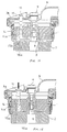
- FIG. 11 shows a condition before two connector housings 1 and 2 are fitted together
- Fig. 12 shows a fitting-uncompleted condition (half-fitted condition)
- Fig. 14 shows a condition immediately before the completion of the fitting
- Fig. 15 shows a fitting-completed condition.
- a pin insertion hole 12 for the insertion of a fitting detection pin 11 (later described) thereinto is formed in a left portion (in the drawings) of the female connector housing 1 and extends therethrough in an upward-downward direction.
- a shallow groove 12a is formed in a right portion (in the drawings) of the pin insertion hole 12 and extends downwardly except for an upper end portion thereof.
- a deep groove 12b deeper than the shallow groove 12a is formed in a left portion (in the drawings) of the pin insertion hole 12 and extends downwardly except for the upper end portion.
- a retaining wall portion 13 is formed at the upper end of the deep groove 12b of the female connector housing 1, as shown in Fig. 13 and other figures.
- the male connector housing 2 has a projection portion 14 corresponding to the deep groove 12b of the pin insertion hole 12, which projection portion is projected upwardly from a base 2a, as shown in Fig. 11 and other figures.
- a groove 14a is formed in a right portion (in the drawings) of the projection portion 14 and extends downwardly except for an upper end portion thereof.
- the fitting detection pin 11 is made, for example, of a plastics material and has a head 11a of an enlarged diameter at an upper end of its shaft and integral bifurcated insertion pieces 15 and 16 at a distal end portion of its shaft, which insertion pieces extend substantially downwardly, as shown in Fig. 16.
- a pawl 15b having a slanting surface 15a is formed at the distal end of the left insertion piece 15 and is directed outwardly (to the left), and further an outwardly convex portion 15c is formed on this insertion piece and is disposed slightly above pawl 15b.
- a pawl 16a is formed on the distal end of the right insertion piece 16 and is directed outwardly (to the right in the drawngs).
- the insertion pieces 15 and 16 can be resiliently deformed inwardly.
- the fitting detection pin 11 is attached to the female connector housing 1 in such a manner that the pin is inserted into the pin insertion hole 12.
- the pawl 16a of the right insertion piece 16 is engaged in the shallow groove 12a of the pin insertion hole 12, and the retaining wall portion 13 is disposed between the pawl 15b and the convex portion 15c of the left insertion piece 15 so that the fitting detection pin 11 is prevented from movement in both upward and downward directions.
- the projection portion 14 when the two connector housings 1 and 2 are displaced in a connecting direction, the projection portion 14 is inserted into the deep groove 12b of the pin insertion hole 12 from the lower side and is moved upwardly relative thereto. Then, as shown in Figs. 12 and 13, when the two connector housings 1 and 2 are fitted together to a certain degree, that is, in a half-fitted condition, the distal end of the projection portion 14 abuts against the slanting surface 15a of the pawl 15b on the distal end of the insertion piece 15 and urges it upwardly so that the insertion piece 15 held against upward and downward movement is displaced inwardly (to the right).
- the fitting detection pin 11 can be inserted into the pin insertion hole 12, and by pushing the fitting detection pin 11, the fitting detection pin 11 is fully inserted into the pin insertion hole 12 as shown in Fig. 15. At this time, the pawl 15b of the insertion piece 15 becomes engaged in the groove 14a of the projection portion 14.
- this third embodiment also, by realizing how far the fitting detection pin 11 can be inserted, the operator can know whether or not the two connector housings 1 and 2 are in the fitting-completed condition, as in the above embodiments. As a result, an excessive tightening of bolt 4 can be prevented, and also the situation in which the operation is stopped when the two connector housings 1 and 2 are still in the half-fitted condition is prevented. Therefore, there is provided an excellent advantage that the two connector housings 1 and 2 can be positively brought into the fitting-completed condition.
- the pin insertion hole for the insertion of the fitting detection pin thereinto is provided in the one connector housing, and the retaining projection portion is provided on the other connector housing, and the amount of insertion of the fitting detection pin is varied depending on whether or not the two connector housings are in the fitting-completed condition.
- the female connector housing 1 is in the form of a rectangular block as a whole and has a number of female terminals (not shown) provided therein.
- An upper surface portion of female connector housing 1 is covered with a cover 3 made, for example, of rubber.
- a bolt insertion hole 1a is formed through a central portion of the female connector housing 1 in a vertical direction, and a bolt 4 is received in the bolt insertion hole 1a.
- a threaded portion 4a is formed only on a distal end portion of a shaft of the bolt 4, and a bolt head 4b is projected from the upper surface of the female connector housing 1. In this condition, the bolt 4 is rotatable relative to the female connector housing 1 and is supplied with a moving force in a direction of forward and backward threaded movement.
- the male connector housing 2 has a tubular hood portion 2b of a square shape with an open top.
- the hood portion is formed on an upper portion of a rectangular-shaped base 2a.
- the hood portion 2b has a size such that the female connector housing 1 can be fitted therein.
- a number of male terminals (not shown), corresponding respectively to the above-mentioned female terminals, are provided within the male connector housing 2 and supported on the base 2a.
- a nut 6 for threaded engagement with the bolt 4 is provided integrally within the boss 5, for example, by insert molding.
- a projection 7'' serving as a pressing portion is formed integrally on a portion of a lower surface of the female connector housing 1 slightly offset to the left of center, as best shown in Fig. 19.
- a pressure-sensitive element 17 is provided at a portion of the upper surface of the base 2a of the male connector housing 2 slightly offset to the left of center, that is, immediately adjacent to the left side of the boss 5.
- the pressure-sensitive element 17 comprises a pressure-sensitive, electrically-conductive rubber that varies in resistance upon application of pressure.
- a mounting recess 18 is formed in the upper surface of the base 2a, and a hole 19 continuous with the mounting recess 18 extends downwardly and is open to the lower surface of the male connector housing 2.
- the pressure sensitive element 17 has a generally hook-shape as viewed from a side thereof, and a pressure detection surface 17a at an upper end portion thereof is disposed in the mounting recess 18.
- a pair of fitting detection connection terminals 20 and 20 are connected at their upper ends to electrodes of the pressure-sensitive element 17.
- the terminals 20 and 20 output a signal from the pressure-sensitive element 17.
- the two connector housings 1 and 2 are fitted together in the following manner.
- the female connector housing 1 is lightly fitted in the male connector housing 2 from the upper side, so that the threaded portion 4a of the bolt 4 can be threaded into the nut 6.
- a detection circuit (not shown) is beforehand connected to the fitting detection connection terminals 20 and 20. Any one of various kinds of detection circuits can be used as such circuits are well known in the art.
- a simple circuit may include a general-purpose meter, a power source such as a battery, and a lamp or a buzzer serially connected together.
- any type may be used in so far as it can detect a change in the electrical resistance of the pressure sensitive element 17 and can indicate the change to the operator.
- the operator tightens the bolt 4 relative to the nut 6, using a tool such as an impact wrench.
- a tool such as an impact wrench.
- the two connector housings 1 and 2 are displaced relative to each other in the connecting direction to be fitted together, as described above.
- the pressure sensitive element 17 is pressed by the projection 7'', so that the electrical resistance of element 17 decreases.
- the detection circuit detects the pressing of the pressure sensitive element 17.
- the operator stops the tightening operation. Therefore, the tightening of the bolt 4 can be stopped in a suitable condition in which the fitting of the two connector housings 1 and 2 is completed without excessive or insufficient tightening of the bolt 4.
- the projection 7'' formed on the female connector housing 1 presses the pressure sensitive element 17 provided on the male connector housing 2.
- the detection circuit By detecting the output of the pressure sensitive element 17 by the detection circuit, the fitting-completed condition of the two connector housings 1 and 2 can be detected.
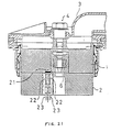
- FIG. 20 A fifth embodiment of the present invention will now be described with reference to Figs. 20 and 21.
- the present invention is applied to a screw tightening-type connector as in the previous embodiments.
- a metal piece 21 for electrical connection purposes is provided on a lower surface of a female connector housing 1, while a pair of conductors 22 and 22 are provided at an upper portion of a base 2a of a male connector housing 2.
- Fitting detection connection terminals 23 and 23 for determining whether or not electrical connection between the conductors 22 and 22 is established are provided within a hole in the base 2a and are connected to the conductors 22 and 22, respectively.
- a conductor and a fitting detection connection terminal may be provided on each of the two connector housings.
- the conductors provided respectively on the two connector housings can be contacted with each other in the fitting-completed condition.
- the fitting-completed condition can be detected during the fitting of the two connector housings 1 and 2 or after the fitting operation.
- the pressure sensitive element 17 and the conductors 22 may be provided on the female connector housing 1.
- the pair of conductors which are electrically connected together in the fitting-completed condition are provided on the connector housing. Therefore, there is achieved an excellent advantage that by detecting whether or not electrical connection between the two conductors is established, the condition of the fitting of the two connector housings can be readily perceived.
Abstract
Description
- This invention relates to a connector in which two connector housings are fitted together, and more particularly to a connector in which a fitting-completed condition of the two connector housings can be detected by a fitting indicator such as a detection pin or electrical detector.
- In connectors, and particularly the type of connector having many terminals, the force for fitting male and female connector housings is large, so that a large force is required for attaching and detaching them. To deal with this, there has been proposed a so-called screw tightening-type connector. In this construction, a bolt is rotatably mounted, for example, on a female connector housing, and a nut is mounted on a male connector housing. The bolt is tightened relative to the nut, thereby fitting the two connector housings together.
- Incidentally, the bolt tightening operation is carried out using a tool such as an impact wrench. If the bolt is tightened excessively, the bolt may be broken, or the housing may be damaged. Therefore, in recent years, there has been proposed a construction in which a threaded portion of a bolt is provided partially on a distal end portion of a bolt shaft, and in a fitting-completed condition of two connector housings, the threaded portion of the bolt extends forwardly from the nut, thereby freely rotating without engagement with the nut. This prevents excessive tightening of the bolt (for example, Japanese Patent Unexamined Publication No. 63-13283).
- However, in the above construction in which the bolt freely rotates in the fitting-completed condition of the two connector housings, an excessive tightening of the bolt is eliminated, but in a tightening operation by an impact wrench, the operator cannot clearly perceive the degree of tightening of the bolt. Accordingly, the operator may stop the tightening operation before the fitting-completed condition of the two connector housings is achieved, that is, in a so-called half-fitted condition.
- The present invention has been made under the above circumstances, and an object of the invention is to provide a connector in which a fitted condition of two connector housings can be easily perceived.
- In order to achieve the above object, the present invention provides a connector wherein a bolt is provided on one connector housing and a nut is provided on the other connector housing. By tightening the bolt relative to the nut, the two connector housings are displaced relative to each other in a connecting direction and fitted together. An indicator is provided on the connector housing, the indicator being displaced in accordance with the displacement of the two connector housings in the connection direction to indicate a fitting-completed condition of the two connector housing.
- In the connector of the present invention having this construction, when the bolt is tightened relative to the nut, the indicator is displaced in accordance with the displacement of the two connector housings in the connecting direction and indicates the fitting-completed condition of the two connector housings. Therefore, by viewing the indicator, the operator can readily know the fitting-completed condition of the two connector housings. Therefore, the operator effects the bolt tightening operation while viewing the indicator, and by doing so, the bolt tightening operation can be stopped in a suitable condition in which the tightening of the bolt is not excessive or insufficient.
- A second embodiment achieves the above object by the provision of a pin insertion hole formed in one connector housing, the hole having opposite open ends; a fitting detection pin having a resilient, inwardly-deformable insertion piece at a distal end thereof, insertable into the pin insertion hole from one end of the pin insertion hole; and a projection portion formed on the other connector housing, insertable into the pin insertion hole from the other end thereof in accordance with the displacement of the two connector housings in a connecting direction. The projection portion retains the fitting detection pin at a distal end thereof to urge the pin toward the one end of the pin insertion hole. When the fitting detection pin is urged by the projection portion, the insertion piece is gradually, resiliently deformed inward. In a fitting-uncompleted condition of the two connector housings, the fitting detection pin is prevented (by retainment by the projection portion) from being further inserted, and in a fitting-completed condition of the two connector housings, the amount of deformation of the insertion piece is large so that the retainment thereof by the projection portion is released. Therefore, the fitting detection pin can be inserted to a position beyond the distal end of the projection portion.
- In order to achieve the above object, the present invention according to a fourth embodiment provides a pressing portion provided on the one connector housing; a pressure sensitive element provided on the other connecting housing and pressed by the pressing portion in a fitting-completed condition of the two connector housings; and fitting detection connection terminals provided on the other connector housing for outputting a signal from the pressure sensitive element.
- The present invention according to a fifth embodiment provides a pair of conductors provided on the connector housing and electrically connected together in a fitting-completed condition of the two connector housings; and fitting detection connection terminals provided on the connector housing for detecting whether or not electrical connection between the conductors is made.
- In the first connector of the present invention having the above construction, in the fitting-completed condition of the two connector housings, the pressing portion provided on the one connector housing presses the pressure sensitive element provided on the other connector housing, so that the output of the pressure sensitive element is changed. Therefore, by connecting a detection circuit to the fitting detection connection terminals to output a signal from the pressure sensitive element, the fitting-completed condition can be detected.
- In the second connector of the present invention, in the fitting-completed condition of the two connector housings, the pair of conductors provided on the connector housing are electrically connected together. Therefore, by connecting the detection circuit to the fitting detection connection terminals, the fitting-completed condition of the two connector housings can be detected.
- The preferred embodiments will be described with reference to the drawings in which:
- Fig. 1 is a vertical cross-sectional, front view of one embodiment of the present invention, showing a condition before two connector housings are fitted together;
- Fig. 2 is an enlarged, vertical cross-sectional, front view showing a distal end portion of a detection pin;
- Fig. 3 is a vertical cross-sectional, front view showing a fitting-completed condition of the two connector housings;
- Fig. 4 is an enlarged, vertical cross-sectional, front view, showing the distal end portion of the detection pin in the fitting-completed condition;
- Fig. 5 is a vertical cross-sectional, front view of a second embodiment of the present invention, showing a fitting-uncompleted condition of two connector housings;
- Fig. 6 is an enlarged view showing a distal end portion of a fitting detection pin;
- Fig. 7 is a vertical cross-sectional, front view showing a condition immediately before the fitting of the two connector housings is completed;
- Fig. 8 is a vertical cross-sectional, front view showing a fitting-completed condition of the two connector housings;
- Fig. 9 is a vertical cross-sectional, front view showing a condition before the fitting detection pin is attached to the female connector housing;
- Fig. 10 is a vertical cross-sectional, front view showing a condition in which the fitting detection pin is attached to the female connector housing;
- Fig. 11 is a vertical cross-sectional, front view of a third embodiment of the present invention, showing a condition before two connector housings are fitted together;
- Fig. 12 is a vertical cross-sectional, front view showing a fitting-completed condition;
- Fig. 13 is a cross-sectional view showing a distal end portion of a fitting detection pin on an enlarged scale;
- Fig. 14 is a vertical cross-sectional, front view showing the fitting process;
- Fig. 15 is a vertical cross-sectional, front view showing a fitting-completed condition;
- Fig. 16 is a vertical cross-sectional, front view showing a condition before the fitting detection pin is attached;
- Fig. 17 is a vertical cross-sectional, front view of a fourth embodiment of the present invention, showing a condition before the completion of the fitting of two connector housings;
- Fig. 18 is a vertical cross-sectional, front view showing a fitting-completed condition of the two connector housings;
- Fig. 19 is an enlarged, vertical cross-sectional, side view of a portion of a connector housing;
- Fig. 20 is a view similar to Fig. 17, showing a fifth embodiment of the present invention; and
- Fig. 21 is a view similar to Fig. 18.
- A first embodiment will now be described with reference to the drawings. Figs. 1 and 2 show a condition before two
connector housings connector housings - A
female connector housing 1 is in the form of a rectangular block as a whole and has a number of female terminals (not shown) provided therein. An upper surface portion offemale connector housing 1 is covered with acover 3 made, for example, of rubber. - A bolt insertion hole 1a is formed through a central portion of the female connector housing 1 in a vertical direction, and a
bolt 4 is received in the bolt insertion hole 1a. A threadedportion 4a is formed only on a distal end portion of a shaft of thebolt 4, and abolt head 4b is projected from the upper surface of thefemale connector housing 1. In this condition, thebolt 4 is rotatable relative to thefemale connector housing 1 and is supplied with a moving force in a direction (vertical direction in the drawings) of forward and backward threaded movement. - The
male connector housing 2 has atubular hood portion 2b of a square shape with an open top. The hood portion is formed on an upper portion of abase 2a, which is of a rectangular shape. Thehood portion 2b has such a size that thefemale connector housing 1 can be fitted therein. A number of male terminals (not shown), corresponding respectively to the previously-mentioned female terminals, are provided within themale connector housing 2 and are supported on thebase 2a. - A
boss 5, having a throughhole 5a vertically extending therethrough, is provided at a central portion of themale connector housing 2, and is projected upward from and formed integrally with thebase 2a. Anut 6 for threaded engagement with thebolt 4 is provided integrally within theboss 5, for example, by insert molding. With this arrangement, by tightening the threadedportion 4a of thebolt 4 relative to thenut 6, the twoconnector housings connector housings - A bar-
like projection portion 7 is provided in themale connector housing 2 at a left portion thereof (in the drawings), and extends upward from thebase 2a. Thisprojection portion 7 extends generally to a level of an upper surface of thehood portion 2b. Aninsertion hole 8 corresponding to theprojection portion 7 is formed through thefemale connector housing 1 and extends in the vertical direction. Thisinsertion hole 8 has a stepped configuration such that its upper end portion is slightly larger in diameter than its lower portion. Adetection pin 9, which is elongated in the vertical direction and functions as an indicator, is inserted into this upper end portion of a larger diameter from the upper side. - The lower end of the
detection pin 9 is retained by a stepped portion of theinsertion hole 8, so that its downward movement is limited. As shown in Fig. 2, this detection pin is inserted into aboss 3a, formed on thecover 3, from the lower side. An upper surface of theboss 3a is formed in athin portion 3b that can be easily broken. Preferably, thedetection pin 9 has a bright color different from that of thecover 3. - With this construction, when the two
connector housings projection portion 7 is inserted into theinsertion hole 8, moves upward relative thereto, and finally urges the lower end of thedetection pin 9 upward. Then, as shown in Figs. 3 and 4, when the lower surface of thefemale connector housing 1 is mated with the upper surface of thebase 2a, that is, the fitting of the twoconnector housings detection pin 9 pierces thethin portion 3b of thecover 3, projecting from the upper surface and exposed to the exterior. - In the above construction, the two
connector housings female connector housing 1 is lightly fitted in the male connector housing from the upper side, so that the threadedportion 4a ofbolt 4 can be threaded intonut 6. At this time, the upper end portion of theprojection portion 7 is slightly inserted into theinsertion hole 8. - Then, the operator tightens the
bolt 4 relative to thenut 6, using a tool such as an impact wrench. As a result, the twoconnector housings projection portion 7 moves upward within theinsertion hole 8 relative thereto and pushes the lower end of thedetection pin 9 upwardly. Then, as shown in Figs. 3 and 4, when thebolt 4 is tightened until the fitting of the twoconnector housings detection pin 9 pierces thethin portion 3b of thecover 3, projecting upward from the upper surface and is exposed to the exterior. - The operator stops the tightening operation when he recognizes the
detection pin 9 projecting from the upper surface. Therefore, the tightening operation can be completed in a suitable manner, that is, in the fitting-completed condition of the twoconnector housings bolt 4 is not excessively or insufficiently tightened. Thus, thedetection pin 9 indicates the fitting-completed condition in accordance with the displacement of the twoconnector housings bolt 4. - There is provided an excellent advantage in the invention that the two
connector housings thin portion 3b is formed on thecover 3, and thedetection pin 9 pierces thisthin portion 3b to project from the upper surface. With this construction, when thedetection pin 9 is not projected upward before the completion of fitting of the connector, thedetection pin 9 is not seen even if viewed from above the connector. When thedetection pin 9 is projected upward upon completion of the fitting of the connector, this pin can be viewed for the first time. Therefore, an incorrect confirmation of thedetection pin 9 can be prevented. - In the above embodiment, the
detection pin 9 is urged and displaced by theprojection portion 7 to pierce thethin portion 3b of thecover 3; however, the shape of the indicator, as well as the structure for displacing the indicator, can be modified, and the invention is not meant to be limited. For example, a viewing window may be provided on the connector housing so that the displacement of the indicator can be displayed, or the indicator may be swingingly displaced to indicate the fitting-completed condition. - Further, the present invention can be suitably modified without departing from the scope thereof. For example, the bolt may be provided on the male connector housing while the nut is provided on the female connector housing. There can additionally be used a construction in which the threaded portion of the bolt can extend forward from the nut to freely rotate in the fitting-completed condition of the two connector housings.
- A connector of the invention according to a second embodiment is shown in Figs. 5-10 and includes a
female connector housing 1 in the form of a rectangular block as a whole and has a number of female terminals (not shown) provided therein. Acover 3 made, for example, of rubber is attached to an upper surface of thefemale connector housing 1 by acover holder 3a. - A bolt insertion hole 1a is formed through a central portion of the
female connector housing 1 in a vertical direction, and abolt 4 is received in the bolt insertion hole 1a. A threadedportion 4a is formed only on a distal end portion of a shaft of thebolt 4, and abolt head 4b is projected from the upper surface of thefemale connector housing 1. In this condition, thebolt 4 is rotatable relative to thefemale connector housing 1 and is supplied with a moving force in a direction (vertical direction in the drawings) by forward and backward threaded movement. - As shown in Figs. 5, 7 and 8, the
male connector housing 2 has atubular hood portion 2b of a square shape with an open top, which hood portion is formed on an upper portion of abase 2a of a rectangular shape. Thehood portion 2b has such a size that thefemale connector housing 1 can be fitted therein. A number of male terminals (not shown), corresponding respectively to the previously-mentioned female terminals, are provided within themale connector housing 2 and are supported on thebase 2a. - A
boss 5 is provided at a central portion of themale connector housing 2, and is projected upwardly from and formed integrally with thebase 2a. Anut 6 for threaded engagement with thebolt 4 is provided integrally within theboss 5, for example, by insert molding. With this arrangement, by tightening the threadedportion 4a of thebolt 4 relative to thenut 6, the twoconnector housings connector housings - A pin insertion hole 8' for the insertion of a fitting detection pin 9' (later described) thereinto is formed in a left portion (in the drawings) of the
female connector housing 1 and extends therethrough in a vertical direction. As shown in Fig. 9, the pin insertion hole 8' has a smaller-diameter portion 8a at its upper end portion, a taperedportion 8b, which extends from this smaller-diameter portion to an intermediate portion and increases in diameter progressively downwardly. A lower half portion of a larger diameter extends to a lower end of the hole without changing its diameter. Aninsertion port 10 is formed in thecover 3 and thecover holder 3a and is disposed in registry with the upper end portion of the pin insertion hole 8'. On the other hand, as shown in Fig. 5, themale connector housing 2 has a projection portion 7' in the form of a cylindrical boss that is projected upwardly from thebase 2a, and is disposed in registry with the pin insertion hole 8'. Aninsertion hole 7a is formed through the projection portion 7' in a vertical direction. - The fitting detection pin 9' is made, for example, of a plastics material and has
integral insertion pieces insertion port 10, theinsertion pieces head 9b of an enlarged diameter is formed on the upper end of the fitting detection pin 9'. Theinsertion pieces - The fitting detection pin 9' is beforehand received at its distal end portion in the pin insertion hole 8' of the female connector housing. In this case, for setting the fitting detection pin 9' on the
female connector housing 1, theinsertion pieces insertion port 10. As a result, theinsertion pieces portion 8b of the pin insertion hole 8', with thehead 9b placed on the upper surface of theinsertion port 10. - Next, the operation for fitting the two
connector housings female connector housing 1, having the fitting detection pin 9' beforehand attached thereto as described above, is lightly fitted into themale connector housing 2 from the upper side, so that the threadedportion 4a of thebolt 4 can now be threaded into thenut 6. - Then, the operator tightens the
bolt 4 relative to thenut 6 using a tool such as an impact wrench. As a result, the twoconnector housings connector housings connector housings insertion hole 7a) of the projection portion 7' retains theinsertion pieces - When this fitting detection pin 9' is pushed back upwardly, the
insertion pieces connector housings insertion pieces insertion pieces insertion hole 7a of the projection portion 7'. Therefore, in the fitting-uncompleted condition of the twoconnector housings - Then, when the two
connector housings insertion pieces insertion pieces insertion pieces insertion hole 7a. Therefore, in this condition, the fitting detection pin 9' can be inserted to a position beyond the distal end of the projection portion 7', and by pushing the fitting detection pin 9', the distal end portion of the fitting detection pin 9' is inserted into theinsertion hole 7a, as shown in Fig. 8. Therefore, by realizing how far the fitting detection pin 9' can be inserted, the operator can know whether or not the twoconnector housings - In this embodiment, depending on whether or not the two
connector housings connector housings connector housings bolt 4 can be prevented, and also the situation in which the operation is stopped when the twoconnector housings connector housings - A third embodiment of the present invention will now be described with reference to Figs. 11 to 16. Fig. 11 shows a condition before two
connector housings - In this embodiment, as shown in Fig. 16 and other figures, a
pin insertion hole 12 for the insertion of a fitting detection pin 11 (later described) thereinto is formed in a left portion (in the drawings) of thefemale connector housing 1 and extends therethrough in an upward-downward direction. Ashallow groove 12a is formed in a right portion (in the drawings) of thepin insertion hole 12 and extends downwardly except for an upper end portion thereof. Adeep groove 12b deeper than theshallow groove 12a is formed in a left portion (in the drawings) of thepin insertion hole 12 and extends downwardly except for the upper end portion. With this arrangement, aretaining wall portion 13 is formed at the upper end of thedeep groove 12b of thefemale connector housing 1, as shown in Fig. 13 and other figures. Themale connector housing 2 has aprojection portion 14 corresponding to thedeep groove 12b of thepin insertion hole 12, which projection portion is projected upwardly from abase 2a, as shown in Fig. 11 and other figures. Agroove 14a is formed in a right portion (in the drawings) of theprojection portion 14 and extends downwardly except for an upper end portion thereof. - The
fitting detection pin 11 is made, for example, of a plastics material and has ahead 11a of an enlarged diameter at an upper end of its shaft and integralbifurcated insertion pieces pawl 15b having a slantingsurface 15a is formed at the distal end of theleft insertion piece 15 and is directed outwardly (to the left), and further an outwardlyconvex portion 15c is formed on this insertion piece and is disposed slightly abovepawl 15b. Apawl 16a is formed on the distal end of theright insertion piece 16 and is directed outwardly (to the right in the drawngs). Theinsertion pieces - The
fitting detection pin 11 is attached to thefemale connector housing 1 in such a manner that the pin is inserted into thepin insertion hole 12. In this condition, thepawl 16a of theright insertion piece 16 is engaged in theshallow groove 12a of thepin insertion hole 12, and theretaining wall portion 13 is disposed between thepawl 15b and theconvex portion 15c of theleft insertion piece 15 so that thefitting detection pin 11 is prevented from movement in both upward and downward directions. - In this embodiment, when the two
connector housings projection portion 14 is inserted into thedeep groove 12b of thepin insertion hole 12 from the lower side and is moved upwardly relative thereto. Then, as shown in Figs. 12 and 13, when the twoconnector housings projection portion 14 abuts against the slantingsurface 15a of thepawl 15b on the distal end of theinsertion piece 15 and urges it upwardly so that theinsertion piece 15 held against upward and downward movement is displaced inwardly (to the right). Then, when the twoconnector housings insertion piece 15 becomes maximum, so that thepawl 15b is displaced right from theprojection portion 14, and theconvex portion 15c is disposed on the right side of theretaining wall portion 13. - Therefore, in this condition, the
fitting detection pin 11 can be inserted into thepin insertion hole 12, and by pushing thefitting detection pin 11, thefitting detection pin 11 is fully inserted into thepin insertion hole 12 as shown in Fig. 15. At this time, thepawl 15b of theinsertion piece 15 becomes engaged in thegroove 14a of theprojection portion 14. - Thus, in this third embodiment, also, by realizing how far the
fitting detection pin 11 can be inserted, the operator can know whether or not the twoconnector housings bolt 4 can be prevented, and also the situation in which the operation is stopped when the twoconnector housings connector housings - In each of the above embodiments, in the fitting operation of the two
connector housings fitting detection pin fitting detection pin male connector housing 2 while the projection portion may be provided at thefemale connector housing 1. - In the connector of the present invention, as described above, the pin insertion hole for the insertion of the fitting detection pin thereinto is provided in the one connector housing, and the retaining projection portion is provided on the other connector housing, and the amount of insertion of the fitting detection pin is varied depending on whether or not the two connector housings are in the fitting-completed condition. With this construction, there is achieved an excellent advantage that by inserting the fitting detection pin into the pin insertion hole, the condition of fitting of the two connector housings can be readily perceived.
- A fourth embodiment in which the present invention is applied to a so-called screw tightening-type connector will now be described with reference to Figs. 17 to 19. As shown in Figs. 17 and 18, the
female connector housing 1 is in the form of a rectangular block as a whole and has a number of female terminals (not shown) provided therein. An upper surface portion offemale connector housing 1 is covered with acover 3 made, for example, of rubber. - A bolt insertion hole 1a is formed through a central portion of the
female connector housing 1 in a vertical direction, and abolt 4 is received in the bolt insertion hole 1a. A threadedportion 4a is formed only on a distal end portion of a shaft of thebolt 4, and abolt head 4b is projected from the upper surface of thefemale connector housing 1. In this condition, thebolt 4 is rotatable relative to thefemale connector housing 1 and is supplied with a moving force in a direction of forward and backward threaded movement. - The
male connector housing 2 has atubular hood portion 2b of a square shape with an open top. The hood portion is formed on an upper portion of a rectangular-shapedbase 2a. Thehood portion 2b has a size such that thefemale connector housing 1 can be fitted therein. A number of male terminals (not shown), corresponding respectively to the above-mentioned female terminals, are provided within themale connector housing 2 and supported on thebase 2a. - A
boss 5, having a throughhole 5a vertically extending therethrough, is provided at a central portion of themale connector housing 2 and is projected upwardly from and formed integrally with thebase 2a. Anut 6 for threaded engagement with thebolt 4 is provided integrally within theboss 5, for example, by insert molding. - A projection 7'' serving as a pressing portion is formed integrally on a portion of a lower surface of the
female connector housing 1 slightly offset to the left of center, as best shown in Fig. 19. A pressure-sensitive element 17 is provided at a portion of the upper surface of thebase 2a of themale connector housing 2 slightly offset to the left of center, that is, immediately adjacent to the left side of theboss 5. In this embodiment, the pressure-sensitive element 17 comprises a pressure-sensitive, electrically-conductive rubber that varies in resistance upon application of pressure. - As shown in Fig. 19, a mounting
recess 18 is formed in the upper surface of thebase 2a, and ahole 19 continuous with the mountingrecess 18 extends downwardly and is open to the lower surface of themale connector housing 2. The pressuresensitive element 17 has a generally hook-shape as viewed from a side thereof, and apressure detection surface 17a at an upper end portion thereof is disposed in the mountingrecess 18. Within thehole 19, a pair of fittingdetection connection terminals sensitive element 17. Theterminals sensitive element 17. - With this arrangement, when the fitting of the two
connector housings sensitive element 17. This renders a high resistance value for the pressuresensitive element 17. On the other hand, as shown in Fig. 18, when the lower surface of thefemale connector housing 1 is mated with the upper surface of thebase 2a in the fitted-completed condition, theprojection 7 is received in the mountingrecess 18 to press thepressure detection surface 17a of the pressuresensitive element 17. By this pressing, the electrical resistance of the pressuresensitive element 17 is decreased. - In the above construction, the two
connector housings female connector housing 1 is lightly fitted in themale connector housing 2 from the upper side, so that the threadedportion 4a of thebolt 4 can be threaded into thenut 6. Also, a detection circuit (not shown) is beforehand connected to the fittingdetection connection terminals sensitive element 17 and can indicate the change to the operator. - The operator tightens the
bolt 4 relative to thenut 6, using a tool such as an impact wrench. As a result, the twoconnector housings bolt 4 is tightened until the fitting of the twoconnector housings sensitive element 17 is pressed by the projection 7'', so that the electrical resistance ofelement 17 decreases. The detection circuit detects the pressing of the pressuresensitive element 17. - In accordance with the detection by the detection circuit, the operator stops the tightening operation. Therefore, the tightening of the
bolt 4 can be stopped in a suitable condition in which the fitting of the twoconnector housings bolt 4. - Thus, in the present invention, in the fitting-completed condition of the two
connector housings female connector housing 1 presses the pressuresensitive element 17 provided on themale connector housing 2. By detecting the output of the pressuresensitive element 17 by the detection circuit, the fitting-completed condition of the twoconnector housings - A fifth embodiment of the present invention will now be described with reference to Figs. 20 and 21. In this embodiment, the present invention is applied to a screw tightening-type connector as in the previous embodiments.
- A
metal piece 21 for electrical connection purposes is provided on a lower surface of afemale connector housing 1, while a pair ofconductors base 2a of amale connector housing 2. Fittingdetection connection terminals conductors base 2a and are connected to theconductors - With this arrangement, when the fitting of the two
connector housings conductors connector housings metal piece 21 interconnects and is contacted with the twoconductors conductors - Therefore, by connecting a detection circuit (not shown) to the fitting
detection connection terminals connector housings connector housings - In this second embodiment, although the pair of
conductors male connector housing 2 and can be electrically connected together by the connectingmetal piece 21 provided on thefemale connector housing 1, a conductor and a fitting detection connection terminal may be provided on each of the two connector housings. In this case, the conductors provided respectively on the two connector housings can be contacted with each other in the fitting-completed condition. - In each of the above embodiments, the fitting-completed condition can be detected during the fitting of the two
connector housings sensitive element 17 and theconductors 22 may be provided on thefemale connector housing 1. - In this embodiment, the pair of conductors which are electrically connected together in the fitting-completed condition are provided on the connector housing. Therefore, there is achieved an excellent advantage that by detecting whether or not electrical connection between the two conductors is established, the condition of the fitting of the two connector housings can be readily perceived.
- While the invention has been described with reference to preferred embodiment, these embodiments are not intended to be limiting. Various modifications can be made without departing from the scope of the appended claims.
Claims (19)
- A connector including a first connector housing and a second conector housing, wherein a bolt is provided on said first connector housing, a nut is provided on said second connector housing, and by tightening said bolt relative to said nut, said first and second connector housings are displaced relative to each other in a connecting direction to be fitted together, the connector comprising:
an indicator disposed on one of said first and second connector housings, said indicator being displaced in accordance with the displacement of said first and second connector housings in the connection direction to indicate a fitting-completed condition of said first and second connector housings. - The connector of claim 1, wherein said indicator comprises:
a bar-like projection on said second housing extending from a base of said second housing;
an insertion aperture in said first housing opposing said projection and sized to receive said projection;
a detection pin movable within said insertion aperture between a concealed position and a visible position, said projection movably positioning said detection pin to the visible position upon a fitting-completed condition of said first and second housings. - The connector of claim 2, wherein said first housing includes a cover having a thin portion, said detection pin piercing said thin portion of said cover when said detector pin is moved to the visible position.
- The connector of claim 2, wherein said insertion aperture has a stepped portion, defining a first diameter portion and a reduced diameter portion, said projection being sized to move within both said first diameter portion and said reduced diameter portion, said detection pin being sized to move only within said first diameter portion.
- The connector of claim 2, wherein said indicator is of a color sharply contrasting from the remainder of the connector.
- A connector wherein a first connector housing and a second connector housing are displaced relative to each other in a connecting direction so that said first and second connector housings can be fitted together, the connector further comprising:
a pin insertion aperture formed in said first connector housing and having opposite open ends;
a fitting detection pin having a resiliently inwardly-deformable insertion piece at a distal end thereof, said detection pin being inserted into said pin insertion aperture from one end of said pin insertion aperture; and
a projection portion formed on said second connector housing, said projection portion being inserted into said pin insertion aperture from the other end thereof in accordance with the displacement of said first and second connector housings in the connecting direction, said projection pin retaining said fitting detection pin at a distal end thereof to urge said detection pin toward the one end of said pin insertion aperture,
wherein when said fitting detection pin is urged by said projection portion, said insertion piece is gradually resiliently deformed inwardly, in a fitting-uncompleted condition of said first and second connector housings, said fitting detection pin is retained from further insertion by said projection portion, and in a fitting-completed condition of said two connector housings, the amount of deformation of the insertion piece is large, so that the retaining thereof by said projection portion is released, and therefore said fitting detection pin can be inserted within the distal end of said projection portion. - The connector of claim 6, wherein said pin insertion aperture includes a first vertically extending groove and an opposing second vertically extending groove, said second extending groove terminating at a retaining wall portion extending inward into said pin insertion aperture.
- The connector of claim 7, wherein said detection pin includes two inwardly deformable pawls, one being engageable within said first groove and guidable therealong and the other pawl being engageable within said second groove and guidable therealong.
- The connector of claim 8, wherein said detection pin additionally includes a third pawl located above said retaining wall, said detection pin being restrained from movement within said pin insertion hole by said third pawl being on one side of said retaining wall and said first pawl being located on an opposite side of said retaining wall.
- The connector of claim 8, wherein said projection portion comprises an inclined surface for inwardly deforming said first pawl in a fitting-completed condition, thereby allowing said detection pin to freely move within said pin insertion aperture.
- A connector including a first connector housing and a second connector housing displaced relative to each other in a connecting direction so that said first and second housings can be fitted together, the connector further comprising:
a pressing portion provided on said first connector housing;
a pressure sensitive element provided on said second connecting housing and pressed by said pressing portion in a fitting-completed condition of said first and second connector housings; and
fitting detection connection terminals provided on said second connector housing for outputting a signal from said pressure sensitive element. - The connector of claim 11, wherein said pressure sensitive element outputs a varying resistance signal depending on the pressure exerted on said element.
- The connector of claim 11, wherein a detection circuit is electrically connected to said connection terminals to visually indicate a fitting-completed condition.
- The connector of claim 13, wherein said detection circuit is detachably connected to said connection terminals.
- A connector including a first connector housing and a second connector housing displaced relative to each other in a connecting direction so that said first and second connector housings can be fitted together, the connector further comprising:
a pair of conductors provided on said first connector housing and electrically connected together in a fitting-completed condition of said first and second connector housings; and
fitting detection connection terminals provided on said first connector housing for detecting whether or not electrical connection between said conductors is made. - The connector of claim 15, further comprising an electrically conductive piece on said second housing opposed to said conductors, said conductive piece electrically connecting said conductors in a fitting-completed condition.
- The connector of claim 15, further comprising an indicator responsive to said connection terminals for indicating said fitting-completed condition.
- A connector including a first connector housing and a second connector housing displaced relative to each other in a connecting direction so that said first and second connector housings can be fitted together, the connector further comprising:
a pin insertion aperture formed in said first connector housing and having opposite open ends;
a fitting detection pin which has a resiliently inwardly-deformable insertion piece at a distal end thereof, said detection pin being inserted into said pin insertion aperture from one end of said pin insertion hole; and
a projection portion formed on said second connector housing, said projection portion being inserted into said pin insertion aperture from the other end thereof in accordance with the displacement of said first and second connector housings in the connecting direction. - The connector of claim 18, wherein said projection pin urges said fitting detection pin toward the one end of said pin insertion aperture in a fitting-uncompleted condition of said first and second housings, said insertion piece being gradually resiliently deformed inwardly as said housings are mated together, said insertion piece being deformed to a size in a fitting-complete condition that allows said detection pin to be movable within said pin insertion aperture toward said other end, thereby indicating said fitting-completed condition.
Priority Applications (1)
| Application Number | Priority Date | Filing Date | Title |
|---|---|---|---|
| EP98107248A EP0858131A1 (en) | 1993-03-19 | 1994-03-07 | Matable connector |
Applications Claiming Priority (6)
| Application Number | Priority Date | Filing Date | Title |
|---|---|---|---|
| JP18646/93U | 1993-03-19 | ||
| JP1864493U JPH0672177U (en) | 1993-03-19 | 1993-03-19 | connector |
| JP18644/93U | 1993-03-19 | ||
| JP1864693U JPH0672179U (en) | 1993-03-19 | 1993-03-19 | connector |
| JP1864593U JPH0672178U (en) | 1993-03-19 | 1993-03-19 | connector |
| JP18645/93U | 1993-03-19 |
Related Child Applications (1)
| Application Number | Title | Priority Date | Filing Date |
|---|---|---|---|
| EP98107248A Division EP0858131A1 (en) | 1993-03-19 | 1994-03-07 | Matable connector |
Publications (3)
| Publication Number | Publication Date |
|---|---|
| EP0616392A2 true EP0616392A2 (en) | 1994-09-21 |
| EP0616392A3 EP0616392A3 (en) | 1995-09-06 |
| EP0616392B1 EP0616392B1 (en) | 1998-07-01 |
Family
ID=27282306
Family Applications (2)
| Application Number | Title | Priority Date | Filing Date |
|---|---|---|---|
| EP98107248A Ceased EP0858131A1 (en) | 1993-03-19 | 1994-03-07 | Matable connector |
| EP94103424A Expired - Lifetime EP0616392B1 (en) | 1993-03-19 | 1994-03-07 | Matable connector |
Family Applications Before (1)
| Application Number | Title | Priority Date | Filing Date |
|---|---|---|---|
| EP98107248A Ceased EP0858131A1 (en) | 1993-03-19 | 1994-03-07 | Matable connector |
Country Status (3)
| Country | Link |
|---|---|
| US (2) | US5486119A (en) |
| EP (2) | EP0858131A1 (en) |
| DE (1) | DE69411302T2 (en) |
Cited By (1)
| Publication number | Priority date | Publication date | Assignee | Title |
|---|---|---|---|---|
| EP0779680A3 (en) * | 1995-12-11 | 1998-10-21 | Sumitomo Wiring Systems, Ltd. | Connector assembly for wire harness and method for coupling the same |
Families Citing this family (19)
| Publication number | Priority date | Publication date | Assignee | Title |
|---|---|---|---|---|
| JP3189945B2 (en) * | 1996-09-30 | 2001-07-16 | 矢崎総業株式会社 | Movable connector |
| US5733152A (en) * | 1996-10-09 | 1998-03-31 | Royal Die & Stamping Co., Inc. | Battery terminal adaptor and connector |
| US5876238A (en) * | 1997-06-17 | 1999-03-02 | International Business Machines Corporation | Device and method for securing integrity of a blind autodock electrical connection |
| US6231369B1 (en) * | 1997-12-11 | 2001-05-15 | The Furukawa Electric Co., Ltd. | Bolted type connector |
| US5971798A (en) * | 1997-12-16 | 1999-10-26 | Sundstrand Corporation | Quick release power connector |
| ES2154240B1 (en) * | 1999-08-10 | 2001-10-16 | Mecanismos Aux Es Ind S L | ELECTRICAL CONNECTOR ASSEMBLY DEVICE FOR VEHICLES. |
| JP3349484B2 (en) * | 1999-11-09 | 2002-11-25 | 住友電装株式会社 | Detachment detection system for joints |
| DE10026968A1 (en) * | 2000-05-31 | 2001-12-06 | Volkswagen Ag | Test apparatus for waterproof connectors for motor vehicle control equipment has moisture-sensitive contacts connected to contact elements of plug connector |
| JP4058902B2 (en) | 2000-12-18 | 2008-03-12 | 住友電装株式会社 | Waterproof connector |
| DE10334071B4 (en) * | 2003-07-25 | 2005-07-07 | Siemens Ag | Plug connection system with integrated lock |
| US6855008B1 (en) | 2003-10-06 | 2005-02-15 | Royal Die & Stamping Co., Inc. | Fuse holder with adjustable terminals |
| US6932650B1 (en) | 2004-03-25 | 2005-08-23 | Royal Die & Stamping Co., Inc. | Fused battery terminal connector |
| US7614897B2 (en) * | 2008-02-15 | 2009-11-10 | Lear Corporation | Electrical connector system and method of assembly |
| JP5378955B2 (en) * | 2009-11-04 | 2013-12-25 | 矢崎総業株式会社 | Connector structure |
| JP5848647B2 (en) * | 2012-03-21 | 2016-01-27 | 株式会社小松製作所 | Electric motor interlock mechanism and electric motor |
| CN103902432A (en) * | 2012-12-29 | 2014-07-02 | 鸿富锦精密工业(深圳)有限公司 | Electronic device and USB interface connecting condition indicating circuit thereof |
| US10008789B1 (en) | 2017-07-10 | 2018-06-26 | Royal Die & Stamping, Llc | Angled bolt T-bar battery terminal clamp |
| TWI662218B (en) * | 2018-06-04 | 2019-06-11 | 訊凱國際股份有限公司 | Connector assembly |
| US10903608B1 (en) | 2019-08-27 | 2021-01-26 | International Business Machines Corporation | Multi-directional motion monitoring of plugged electrical connector |
Citations (5)
| Publication number | Priority date | Publication date | Assignee | Title |
|---|---|---|---|---|
| FR2580434A1 (en) * | 1985-04-12 | 1986-10-17 | Vibrachoc Sa | Device for visually indicating that an electronic-equipment module (box) has been plugged into an aircraft panel (plate) |
| US4629351A (en) * | 1983-06-17 | 1986-12-16 | Nissan Motor Co., Ltd. | Fitting indicating mechanism in screw type connector housings |
| US4907118A (en) * | 1989-03-09 | 1990-03-06 | Curtis Manufacturing Company, Inc. | Visual indicator electrical plug-type surge protector and systems |
| EP0448083A1 (en) * | 1990-03-23 | 1991-09-25 | Yazaki Corporation | A connector engagement detecting apparatus |
| US5192225A (en) * | 1990-11-08 | 1993-03-09 | Yazaki Corporation | Connector locking connection detection device |
Family Cites Families (7)
| Publication number | Priority date | Publication date | Assignee | Title |
|---|---|---|---|---|
| US4015888A (en) * | 1975-11-05 | 1977-04-05 | Square D Company | Electrical device with retractable grounding pin and indicating means |
| DE2843247A1 (en) * | 1978-10-04 | 1980-04-17 | Dornier Gmbh | Multiway plug and socket connector with locking monitor - has separate circuit triggered via switch when sections, are fully mated by rotation |
| JPS63132383A (en) * | 1986-11-21 | 1988-06-04 | Toshiba Corp | Straight line stroke extracting method for graphic processor |
| JPH0454162U (en) * | 1990-09-14 | 1992-05-08 | ||
| US5145391A (en) * | 1991-04-29 | 1992-09-08 | Gte Products Corporation | Switching connector assembly |
| US5228867A (en) * | 1991-12-06 | 1993-07-20 | The Whitaker Corporation | Electrical connector bolt fastening device |
| JP2544953Y2 (en) * | 1992-03-06 | 1997-08-20 | 日本エー・エム・ピー株式会社 | connector |
-
1994
- 1994-02-18 US US08/198,282 patent/US5486119A/en not_active Expired - Lifetime
- 1994-03-07 EP EP98107248A patent/EP0858131A1/en not_active Ceased
- 1994-03-07 EP EP94103424A patent/EP0616392B1/en not_active Expired - Lifetime
- 1994-03-07 DE DE69411302T patent/DE69411302T2/en not_active Expired - Fee Related
-
1995
- 1995-06-07 US US08/478,783 patent/US5601450A/en not_active Expired - Fee Related
Patent Citations (5)
| Publication number | Priority date | Publication date | Assignee | Title |
|---|---|---|---|---|
| US4629351A (en) * | 1983-06-17 | 1986-12-16 | Nissan Motor Co., Ltd. | Fitting indicating mechanism in screw type connector housings |
| FR2580434A1 (en) * | 1985-04-12 | 1986-10-17 | Vibrachoc Sa | Device for visually indicating that an electronic-equipment module (box) has been plugged into an aircraft panel (plate) |
| US4907118A (en) * | 1989-03-09 | 1990-03-06 | Curtis Manufacturing Company, Inc. | Visual indicator electrical plug-type surge protector and systems |
| EP0448083A1 (en) * | 1990-03-23 | 1991-09-25 | Yazaki Corporation | A connector engagement detecting apparatus |
| US5192225A (en) * | 1990-11-08 | 1993-03-09 | Yazaki Corporation | Connector locking connection detection device |
Cited By (1)
| Publication number | Priority date | Publication date | Assignee | Title |
|---|---|---|---|---|
| EP0779680A3 (en) * | 1995-12-11 | 1998-10-21 | Sumitomo Wiring Systems, Ltd. | Connector assembly for wire harness and method for coupling the same |
Also Published As
| Publication number | Publication date |
|---|---|
| EP0616392A3 (en) | 1995-09-06 |
| EP0616392B1 (en) | 1998-07-01 |
| DE69411302T2 (en) | 1999-01-28 |
| US5486119A (en) | 1996-01-23 |
| US5601450A (en) | 1997-02-11 |
| DE69411302D1 (en) | 1998-08-06 |
| EP0858131A1 (en) | 1998-08-12 |
Similar Documents
| Publication | Publication Date | Title |
|---|---|---|
| US5486119A (en) | Matable connector | |
| EP0649028B1 (en) | Connector inspecting device | |
| JPH0620314Y2 (en) | Terminal insertion tester | |
| EP0300767B1 (en) | Connector | |
| EP0227288A2 (en) | Electrical connector with connector position assurance/assist device | |
| EP0645848A1 (en) | Connector engagement detecting device | |
| GB2270426A (en) | Testing electrical connectors and ensuring contact retention | |
| JP2682594B2 (en) | Connector terminal detection tool | |
| US5775936A (en) | Engagement detection connector | |
| EP0945932A3 (en) | Double plug connection element, adapted male and female element and related connection device | |
| US5904593A (en) | Connector with terminal retaining mechanism | |
| US5108305A (en) | Device for detecting erroneous insertion of insulation displacement terminal | |
| US5179343A (en) | Apparatus for checking the connection between male and female connector housings by forming a detecting circuit when the connection is proper | |
| EP0634821A2 (en) | Bulb socket | |
| US5647762A (en) | Locking structure of short-circuit contact for connectors | |
| JP3043568B2 (en) | connector | |
| JP2557741B2 (en) | Connector lock detection method and connector using the same | |
| JP2916573B2 (en) | Connector indication mechanism | |
| EP0652606B1 (en) | Female terminal metal fixture for connector | |
| EP3128613A1 (en) | Electrical terminal | |
| US7186135B2 (en) | Connector and assembling method therefor | |
| EP3128614A1 (en) | Electrical terminal | |
| JP2797920B2 (en) | Connector inspection device | |
| JP2797934B2 (en) | Connector and connector inspection device | |
| EP1107379A1 (en) | Terminal for detecting incomplete insertion |
Legal Events
| Date | Code | Title | Description |
|---|---|---|---|
| PUAI | Public reference made under article 153(3) epc to a published international application that has entered the european phase |
Free format text: ORIGINAL CODE: 0009012 |
|
| AK | Designated contracting states |
Kind code of ref document: A2 Designated state(s): DE GB |
|
| PUAL | Search report despatched |
Free format text: ORIGINAL CODE: 0009013 |
|
| AK | Designated contracting states |
Kind code of ref document: A3 Designated state(s): DE GB |
|
| 17P | Request for examination filed |
Effective date: 19950927 |
|
| 17Q | First examination report despatched |
Effective date: 19960415 |
|
| GRAG | Despatch of communication of intention to grant |
Free format text: ORIGINAL CODE: EPIDOS AGRA |
|
| GRAG | Despatch of communication of intention to grant |
Free format text: ORIGINAL CODE: EPIDOS AGRA |
|
| GRAH | Despatch of communication of intention to grant a patent |
Free format text: ORIGINAL CODE: EPIDOS IGRA |
|
| GRAH | Despatch of communication of intention to grant a patent |
Free format text: ORIGINAL CODE: EPIDOS IGRA |
|
| GRAA | (expected) grant |
Free format text: ORIGINAL CODE: 0009210 |
|
| AK | Designated contracting states |
Kind code of ref document: B1 Designated state(s): DE GB |
|
| REF | Corresponds to: |
Ref document number: 69411302 Country of ref document: DE Date of ref document: 19980806 |
|
| PLBE | No opposition filed within time limit |
Free format text: ORIGINAL CODE: 0009261 |
|
| STAA | Information on the status of an ep patent application or granted ep patent |
Free format text: STATUS: NO OPPOSITION FILED WITHIN TIME LIMIT |
|
| 26N | No opposition filed | ||
| PGFP | Annual fee paid to national office [announced via postgrant information from national office to epo] |
Ref country code: GB Payment date: 20000301 Year of fee payment: 7 |
|
| PGFP | Annual fee paid to national office [announced via postgrant information from national office to epo] |
Ref country code: DE Payment date: 20000306 Year of fee payment: 7 |
|
| PG25 | Lapsed in a contracting state [announced via postgrant information from national office to epo] |
Ref country code: GB Free format text: LAPSE BECAUSE OF NON-PAYMENT OF DUE FEES Effective date: 20010307 |
|
| GBPC | Gb: european patent ceased through non-payment of renewal fee |
Effective date: 20010307 |
|
| PG25 | Lapsed in a contracting state [announced via postgrant information from national office to epo] |
Ref country code: DE Free format text: LAPSE BECAUSE OF NON-PAYMENT OF DUE FEES Effective date: 20020101 |