EP0634821A2 - Bulb socket - Google Patents
Bulb socket Download PDFInfo
- Publication number
- EP0634821A2 EP0634821A2 EP94110592A EP94110592A EP0634821A2 EP 0634821 A2 EP0634821 A2 EP 0634821A2 EP 94110592 A EP94110592 A EP 94110592A EP 94110592 A EP94110592 A EP 94110592A EP 0634821 A2 EP0634821 A2 EP 0634821A2
- Authority
- EP
- European Patent Office
- Prior art keywords
- bulb
- socket
- terminals
- wedge base
- supplying
- Prior art date
- Legal status (The legal status is an assumption and is not a legal conclusion. Google has not performed a legal analysis and makes no representation as to the accuracy of the status listed.)
- Granted
Links
- 239000002184 metal Substances 0.000 claims description 36
- 229920005989 resin Polymers 0.000 claims description 10
- 239000011347 resin Substances 0.000 claims description 10
- 230000000452 restraining effect Effects 0.000 claims description 6
- 238000003780 insertion Methods 0.000 description 31
- 230000037431 insertion Effects 0.000 description 31
- 239000000463 material Substances 0.000 description 10
- 238000000465 moulding Methods 0.000 description 9
- 238000010276 construction Methods 0.000 description 6
- 238000004519 manufacturing process Methods 0.000 description 4
- 238000005452 bending Methods 0.000 description 2
- 238000012986 modification Methods 0.000 description 2
- 230000004048 modification Effects 0.000 description 2
- 230000002265 prevention Effects 0.000 description 2
- 238000002347 injection Methods 0.000 description 1
- 239000007924 injection Substances 0.000 description 1
- 239000007769 metal material Substances 0.000 description 1
- 238000000034 method Methods 0.000 description 1
- 229910001220 stainless steel Inorganic materials 0.000 description 1
- 239000010935 stainless steel Substances 0.000 description 1
- 229920003002 synthetic resin Polymers 0.000 description 1
- 239000000057 synthetic resin Substances 0.000 description 1
Images


Classifications
-
- H—ELECTRICITY
- H01—ELECTRIC ELEMENTS
- H01R—ELECTRICALLY-CONDUCTIVE CONNECTIONS; STRUCTURAL ASSOCIATIONS OF A PLURALITY OF MUTUALLY-INSULATED ELECTRICAL CONNECTING ELEMENTS; COUPLING DEVICES; CURRENT COLLECTORS
- H01R33/00—Coupling devices specially adapted for supporting apparatus and having one part acting as a holder providing support and electrical connection via a counterpart which is structurally associated with the apparatus, e.g. lamp holders; Separate parts thereof
- H01R33/05—Two-pole devices
- H01R33/06—Two-pole devices with two current-carrying pins, blades or analogous contacts, having their axes parallel to each other
- H01R33/09—Two-pole devices with two current-carrying pins, blades or analogous contacts, having their axes parallel to each other for baseless lamp bulb
-
- Y—GENERAL TAGGING OF NEW TECHNOLOGICAL DEVELOPMENTS; GENERAL TAGGING OF CROSS-SECTIONAL TECHNOLOGIES SPANNING OVER SEVERAL SECTIONS OF THE IPC; TECHNICAL SUBJECTS COVERED BY FORMER USPC CROSS-REFERENCE ART COLLECTIONS [XRACs] AND DIGESTS
- Y10—TECHNICAL SUBJECTS COVERED BY FORMER USPC
- Y10S—TECHNICAL SUBJECTS COVERED BY FORMER USPC CROSS-REFERENCE ART COLLECTIONS [XRACs] AND DIGESTS
- Y10S439/00—Electrical connectors
- Y10S439/918—Multilamp vehicle panel
Definitions
- One conventional socket for holding a wedge base bulb to supply electric power thereto is disclosed in Japanese Utility Model Unexamined Publication No. 2-47787.
- a pair of metal members are attached to a socket body, and a supplying terminal portion and a resiliently-engageable portion, which are formed on each of these metal members, are exposed in a bulb insertion hole.
- two power terminals mounted on the base portion are contacted respectively with the supplying terminals of the two metal members, so that electric power can be supplied to the wedge base bulb.
- rugged portions formed on the base portion engage the resiliently-engageable portions of the two metal members, respectively, so that the base portion is held between the two resiliently-engageable portions to thereby prevent the wedge base bulb from withdrawal.
- the supplying terminal portion, for supplying electric power to the wedge base bulb, and the resiliently-engageable portion, for holding the wedge base bulb are formed as an integral metal member made of a single material. Therefore, the material of the metal member is required to perform both the function to reduce the contact resistance and the function to increase the resilient force of the resiliently-engageable portion; however, there exists no material which achieve both functions at a high level at low costs, and as a result both functions have not been entirely satisfactory.
- a socket body 10 of the bulb socket A is made of a synthetic resin material. And the socket body 10 has a bulb insertion hole 11 for receiving the base portion 3 of the wedge base bulb B, and a connector insertion hole 12 for connecting a power supply connector (not shown) thereto.
- the bulb insertion hole 11 and the connector insertion hole 12 are open perpendicularly to each other, and the socket body 10 assuming an L-shape as a whole, as shown in Fig. 2.
- Two supplying terminals 13 shown in Figs. 4 to 6) for supplying electric power to the wedge base bulb B, as well as two holder metal members 14 (shown in Figs. 7 to 9) for holding the wedge base bulb B against withdrawal, are mounted on the socket body 10.
Landscapes
- Connecting Device With Holders (AREA)
- Fastening Of Light Sources Or Lamp Holders (AREA)
Abstract
Description
- This invention relates to a bulb socket for holding a wedge base bulb to supply electric power thereto.
- One conventional socket for holding a wedge base bulb to supply electric power thereto is disclosed in Japanese Utility Model Unexamined Publication No. 2-47787. In this construction, a pair of metal members are attached to a socket body, and a supplying terminal portion and a resiliently-engageable portion, which are formed on each of these metal members, are exposed in a bulb insertion hole. When a base portion of the wedge base bulb is fitted in the bulb insertion hole, two power terminals mounted on the base portion are contacted respectively with the supplying terminals of the two metal members, so that electric power can be supplied to the wedge base bulb. At the same time, rugged portions formed on the base portion engage the resiliently-engageable portions of the two metal members, respectively, so that the base portion is held between the two resiliently-engageable portions to thereby prevent the wedge base bulb from withdrawal.
- When attaching the wedge base bulb to the socket, it is desirable that a contact resistance at that of contact between each supplying terminal and the associated power terminal be low, and it is also desirable that a resilient force at that portion of contact between each resiliently-engageable portion and the associated rugged portion be large.
- However, in the conventional construction, the supplying terminal portion, for supplying electric power to the wedge base bulb, and the resiliently-engageable portion, for holding the wedge base bulb, are formed as an integral metal member made of a single material. Therefore, the material of the metal member is required to perform both the function to reduce the contact resistance and the function to increase the resilient force of the resiliently-engageable portion; however, there exists no material which achieve both functions at a high level at low costs, and as a result both functions have not been entirely satisfactory.
- In the meantime, a requirement for such a bulb socket, when used on a vehicle body, is that the amount of rearward projection of a light device should be reduced. Therefore, there is known a construction in which the other end of each metal member exposed in a bulb insertion hole is extended perpendicularly to the bulb insertion hole, so that the whole of the bulb socket assumes an L-shape.
- In this case, the metal member is also of an L-shape, and hence can not be inserted into a casing through the bulb insertion hole after the casing is molded, and therefore there has been used a method (hereinafter referred to as "insert molding") in which a resin is molded on the periphery of the metal members while holding the metal members.
- However, setting apart from the case where the metal member has a simple configuration, when the configuration is complicated as shown in the above-mentioned publication, such an insert molding is difficult because a gap may be formed between the metal member and a mold during the insert molding as a result of lowered dimensional accuracies, so that a resin flows into such a gap, and also the metal member may interfere with the mold, and the metal members can not be sufficiently held by the mold. As a result, by an injection pressure, the metal members are deformed, and the resin is caused to flow. Furthermore, if the mold is complicated, it is difficult to feed the parts by a part feeder in an automated production.
- It is an object of this invention to provide a construction in which the function to reduce a contact resistance at power supply portions for a wedge base bulb and the function to secure a high holding force at those portions of engagement with the wedge base bulb are both achieved at a high level, and the manufacture can be carried out easily even if the configuration of metal members is complicated.
- In order to solve the above problems, the present invention provides a bulb socket for holding a wedge base bulb which has a bulb portion, a base portion and power terminals, the bulb socket comprising a socket body, supplying terminals and holder members. The socket body is provided for receiving the base portion of the wedge base bulb. The supplying terminals are electrically connecting with the respective power terminals of the wedge base bulb under a predetermined pressure, and are held by the socket body The holder members are holding the base portion of the wedge base bulb therebetween under a predetermined pressure. And the holder members are separate from the supplying terminals, and are attached to the socket body.
- To solve another problem, the present invention further provides a bulb socket as described above in which the socket body is made of a resin, and the supplying terminals are integrally molded in the resin.
- In the invention as set forth above, each of the supplying terminals for supplying electric power to the wedge base bulb is separate from the holder member for holding the wedge base bulb. Therefore, a material of the supplying terminal is selected to have such a nature as to achieve only the function to reduce a contact resistance at that portion of contact between the supplying terminal and the power terminal of the wedge base bulb. Also, a material of the holder member is selected to have such a nature as to achieve only the function to increase a resilient holding pressure at those portions of the holder member which hold the wedge base bulb. The holding force by the holder member can be increased, for example, merely by increasing the sheet thickness thereof.
- Furthermore, in the invention, the supplying terminals integrally molded in the resin is separate from the holder member, and is simple in shape. Therefore, the operation for forming such an integral construction can be carried out easily.
- As described above, in the present invention, the material nature of the supplying terminals for supplying electric power to the wedge base bulb is different from the material nature of the holder members for holding the wedge base bulb. Therefore, there is achieved an excellent advantage that the function to reduce the resistance of contact between the supplying terminal and the power terminal of the wedge base bulb, as well as the force of holding of the wedge base bulb by the holder members, can be both achieved at a high level. Particularly, even if the same material is used, the bulb holding force can be increased merely by increasing the sheet thickness of the holder metal member. Of course, electrical connection is not needed for the holder member, and therefore in view of mechanical strength and the cost, stainless steel or the like can be selected as the material of the holder member.
- The supplying terminal is separate from the holder member, and with this arrangement each of them is more simplified in shape as compared with the case where the two are formed integrally with each other. This enables insert molding, and the efficiency of the operation, as well as the reduction of the manufacturing cost, can be achieved by carrying out such insert molding in an automated manner.
-
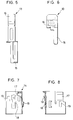
- Fig. 1 is a partly-broken, perspective view of a socket body;
- Fig. 2 is a cross-sectional view of the socket body as viewed in a direction perpendicular to a connector insertion hole in the socket body;
- Fig. 3 is a partly cross-sectional, side-elevational view of the socket body as viewed from the connector insertion hole side;
- Fig. 4 is a right side-elevational view of a supplying terminal;
- Fig. 5 is a front-elevational view of the supplying terminal;
- Fig. 6 is a plan view of the supplying terminal;
- Fig. 7 is a right side-elevational view of a holder metal member;
- Fig. 8 is a cross-sectional view of the holder metal member;
- Fig. 9 is a plan view of the holder metal member; and
- Fig. 10 is a perspective view of a wedge base bulb.
- One preferred embodiment of the present invention will now be described with reference to the drawings.
- A bulb socket A shown in Fig. 1 is adapted to hold a wedge base bulb B of the single filament type shown in Fig. 10. In the wedge base bulb B, a
flattened base portion 3 is integrally molded on a lower portion of a bulb portion 2 which contains a filament 1 therein. And two lead wires 4 extended from a lower surface of thebase portion 3 are folded respectively on opposite (right and left) sides of thebase portion 3 to formpower terminals 5. An upwardly-slanting projection 6 and anabutment projection 7 are formed on each of the opposite right and left sides of thebase portion 3. - A
socket body 10 of the bulb socket A is made of a synthetic resin material. And thesocket body 10 has abulb insertion hole 11 for receiving thebase portion 3 of the wedge base bulb B, and aconnector insertion hole 12 for connecting a power supply connector (not shown) thereto. Thebulb insertion hole 11 and theconnector insertion hole 12 are open perpendicularly to each other, and thesocket body 10 assuming an L-shape as a whole, as shown in Fig. 2. Two supplying terminals 13 (shown in Figs. 4 to 6) for supplying electric power to the wedge base bulb B, as well as two holder metal members 14 (shown in Figs. 7 to 9) for holding the wedge base bulb B against withdrawal, are mounted on thesocket body 10. - The supplying
terminal 13 is formed by bending an elongate strip of an electrically-conductive metal material which can keep a resistance of contact with thepower terminal 5 of thewedge base bulb 5 to a low level. The supplyingterminal 13 has one end portion defining aconnector connecting portion 15 in the form of a flat strip, and abulb connecting portion 16 formed by folding a tip portion of the other end portion extending in a direction perpendicular to theconnector connecting portion 15. - The two supplying
terminals 13 are connected integrally with thesocket body 10 by insert molding during the molding of thesocket body 10 in such a manner that these supplying terminals are held against withdrawal and movement. In this connected condition of these supplyingterminals 13, theconnector connecting portions 15 of the two supplyingterminals 13 are projected into theconnector insertion hole 12 in juxtaposed relation to each other. And the twobulb connecting portions 16 are disposed respectively on opposed right and left sides of the inner surface of thebulb insertion hole 11. - The
holder metal member 14 is formed by bending a sheet of metal having a high elastic coefficient into an L-shape which metal sheet is larger in thickness than the supplyingterminal 13. And a curvedresilient engagement portion 17 is formed on and projected inwardly from one of two perpendicularly-disposed plate portions of theholder member 14 while a part of the other plate portion is stamped and slightly bulged inwardly to form aplay restraining portion 18. Also, a part of each of the two plate portions is stamped and raised obliquely upwardly to form awithdrawal prevention portion 19. - The two
holder metal members 14 are forced into thebulb insertion hole 11 to be attached thereto in such a manner that the outer surfaces of their plate portions are held in intimate contact with the inner surface of the bulb insertion hole. In this attached condition, theresilient engagement portions 17 are disposed respectively on the right and left sides of the inner surface of thebulb insertion hole 11, and theplay restraining portions 18 for the bulb are disposed respectively on the front and rear sides of the inner surface of the bulb insertion hole. Also, in the attached condition, the opposite side edges of theholder metal member 14 are fitted respectively inpositioning grooves 20 in thebulb insertion hole 11, and thewithdrawal prevention portions 19 are engaged respectively withnotches 21 in thebulb insertion hole 11, thereby preventing theholder metal member 14 from shaking and moving in a withdrawing direction. - For attaching the wedge base bulb B to the bulb socket A provided with the supplying
terminals 13 and theholder metal terminals 14, thebase portion 3 of the wedge base bulb B need only to be pushed into thebulb insertion hole 11 of the bulb socket A. At this time, a slantingsurface 6a of each of the upwardly slanting projections 6 of thebase portion 3 abuts against theresilient engagement portion 17 of the correspondingholder metal member 14, and resiliently deforms the same gradually, and simultaneously when theabutment projection 7 abuts against anabutment portion 22 formed on the inner surface of thebulb insertion hole 11, theresilient engagement portion 17 is disengaged from the slantingsurface 6a of the upwardly slanting projection 6 to be resiliently restored. As a result, the two resilient engagement portions resiliently hold thebase portion 3 from the opposite sides thereof, and also are engaged respectively with upwardly-directedengagement surfaces 6b of the upwardly slanting projections 6. Also, thebase portion 3 is resiliently held between theplay restraining portions 18 of theholder metal members 14 in such a manner that theplay restraining portions 18 are strongly pressed respectively against the front and rear sides of thebase portion 3. As a result, thebase portion 3 of the wedge base bulb B is held against withdrawal from thebulb insertion hole 11 and also against shaking. During the insertion of thebase portion 3 into thebulb insertion hole 11, thebulb connecting portions 16 of the supplyingterminals 13 are pressed to be slightly resiliently deformed, so that theseportions 16 are contacted respectively with thepower terminals 5 on thebase portion 3 under a predetermined pressure, thus enabling the supply of electric power. The connector (not shown) is inserted in theconnector insertion hole 12, and theconnector connecting portions 15 of the supplyingterminals 13 are fitted in and contacted with terminals of this connector, respectively, thus enabling the supply of electric power. - On the other hand, the
holder metal member 14 has a high elastic coefficient, and therefore a high holding force is provided at those portions of contact between theholder metal member 14 and the wedge base bulb B. - Only the supplying
terminals 13 are insert molded in thesocket body 10, and theholder metal members 14 are not insert molded. Therefore, as compared with the case where the supplyingterminals 13 and theholder metal members 14 are both inserted molded, the insert operation can be carried out more easily because of a simple shape of the insert members and also of the ease of holding the insert members in a mold. - And besides, since the supplying
terminal 13 is separate from theholder metal member 14, each of them is simpler in shape as compared with the case where the two are formed into an integral construction, and therefore an improved efficiency of the operation, as well as the reduction of the manufacturing cost, can be achieved by carrying out the insert molding in an automated manner. - The present invention is not to be limited to the above embodiment, and for example, the following modifications can be made:
- (a) Although the above embodiment has been described with respect to the bulb socket for holding the wedge base bulb of the single filament type, the present invention can also be applied to a bulb socket for holding a wedge base bulb of the double filament type.
- (b) Although the above embodiment has been described with respect to the bulb socket of a generally L-shape in which the
bulb insertion hole 11 and theconnector insertion hole 12 are open perpendicularly to each other, the present invention can be applied to a bulb socket of such a configuration that a bulb insertion hole and a connector insertion hole are open in opposite directions, respectively. In this case, supplying terminals may be attached by inserting these supplying terminals into one of the two insertion holes in a molded socket body, or the supplying terminals may be made integral with the socket body by insertion molding as in the above embodiment. - The present invention is not limited by the embodiment described above and illustrated in the drawings, and various modifications can be made without departing from the subject matter of the invention.
Claims (5)
- A bulb socket for holding a wedge base bulb which has a bulb portion, a base portion and power terminals, said bulb socket comprising:
a socket body for receiving the base portion of the wedge base bulb;
supplying terminals for electrically connecting with the respective power terminals of the wedge base bulb under a predetermined pressure, said terminals being held by said socket body; and
holding means for holding the base portion of the wedge base bulb therebetween under a predetermined pressure, said holding means being separate from said supplying terminals and being attached to said socket body. - A bulb socket according to claim 1, wherein said socket body is made of a resin, and said supplying terminals are integrally molded in said resin.
- A bulb socket according to claim 1, wherein said holding means is made of metal.
- A bulb socket according to claim 3, wherein said socket body is made of a resin, and said supplying terminals are integrally molded in said resin.
- A bulb socket according to claim 1, wherein said holding means comprises:
a first engagement portion for engaging said holding means with said socket body;
a second engagement portion for engaging said holding means with the base portion of the wedge base bulb; and
a play restraining portion for restraining a play between said holding means and the base portion of the wedge base bulb.
Applications Claiming Priority (2)
| Application Number | Priority Date | Filing Date | Title |
|---|---|---|---|
| JP197863/93 | 1993-07-14 | ||
| JP5197863A JP2874528B2 (en) | 1993-07-14 | 1993-07-14 | Valve socket |
Publications (3)
| Publication Number | Publication Date |
|---|---|
| EP0634821A2 true EP0634821A2 (en) | 1995-01-18 |
| EP0634821A3 EP0634821A3 (en) | 1996-05-22 |
| EP0634821B1 EP0634821B1 (en) | 1999-03-24 |
Family
ID=16381590
Family Applications (1)
| Application Number | Title | Priority Date | Filing Date |
|---|---|---|---|
| EP94110592A Expired - Lifetime EP0634821B1 (en) | 1993-07-14 | 1994-07-07 | Bulb socket |
Country Status (4)
| Country | Link |
|---|---|
| US (1) | US5547402A (en) |
| EP (1) | EP0634821B1 (en) |
| JP (1) | JP2874528B2 (en) |
| DE (1) | DE69417305T2 (en) |
Cited By (2)
| Publication number | Priority date | Publication date | Assignee | Title |
|---|---|---|---|---|
| EP0740375A3 (en) * | 1995-04-28 | 1997-11-12 | Sumitomo Wiring Systems, Ltd. | Bulb socket and the manufacturing method of the same |
| FR2879838A1 (en) * | 2004-12-17 | 2006-06-23 | Valeo Vision Sa | Wedge base filament lamp holder for e.g. traffic light, has spring blade arranged in base for assuring predetermined constraint on wedge base of lamp such that electrodes of lamp and contact blades of holder are pressed with each other |
Families Citing this family (9)
| Publication number | Priority date | Publication date | Assignee | Title |
|---|---|---|---|---|
| US5664870A (en) * | 1995-06-28 | 1997-09-09 | Koito Manufacturing Co., Ltd. | Vehicular lamps |
| DE29906559U1 (en) * | 1999-04-14 | 1999-07-22 | Bender & Wirth GmbH & Co., 58566 Kierspe | Lamp holder for multi-pin lamps |
| DE19958841A1 (en) * | 1999-12-07 | 2001-06-21 | Bjb Gmbh & Co Kg | Lamp holder |
| US7063575B2 (en) * | 2001-10-04 | 2006-06-20 | Guide Corporation | Terminal alignment features for bulb sockets |
| US7014510B2 (en) * | 2001-10-04 | 2006-03-21 | Guide Corporation | Wedge base sealed lamp socket |
| US7052301B2 (en) * | 2003-06-17 | 2006-05-30 | Christiana Industries, Inc. | Lamp socket |
| US20050163911A1 (en) * | 2004-01-28 | 2005-07-28 | Cargill, Inc. | Animal feed product containing crushed urea |
| DE102004007150A1 (en) * | 2004-02-12 | 2005-08-25 | Patent-Treuhand-Gesellschaft für elektrische Glühlampen mbH | Base for a headlamp and headlamp |
| US7479044B1 (en) | 2007-12-07 | 2009-01-20 | St. Clair Technologies, Inc. | Lamp socket |
Family Cites Families (6)
| Publication number | Priority date | Publication date | Assignee | Title |
|---|---|---|---|---|
| GB1326018A (en) * | 1969-12-19 | 1973-08-08 | Carr Fastener Co Ltd | Holder for wedge base lamps |
| US3999095A (en) * | 1975-10-06 | 1976-12-21 | General Motors Corporation | Lamp socket and bulb assembly with side contacts |
| US4647132A (en) * | 1984-12-17 | 1987-03-03 | Ford Motor Company | Retaining mechanism for securing a lamp base within a socket |
| US5120233A (en) * | 1984-12-17 | 1992-06-09 | Ford Motor Company | Retaining mechanism for securing a lamp base with a socket |
| JP2989609B2 (en) * | 1988-08-09 | 1999-12-13 | キヤノン株式会社 | Information processing method and apparatus |
| JP2655921B2 (en) * | 1990-01-16 | 1997-09-24 | 矢崎総業株式会社 | Valve socket and method of manufacturing the same |
-
1993
- 1993-07-14 JP JP5197863A patent/JP2874528B2/en not_active Expired - Lifetime
-
1994
- 1994-06-27 US US08/265,800 patent/US5547402A/en not_active Expired - Fee Related
- 1994-07-07 DE DE69417305T patent/DE69417305T2/en not_active Expired - Fee Related
- 1994-07-07 EP EP94110592A patent/EP0634821B1/en not_active Expired - Lifetime
Cited By (2)
| Publication number | Priority date | Publication date | Assignee | Title |
|---|---|---|---|---|
| EP0740375A3 (en) * | 1995-04-28 | 1997-11-12 | Sumitomo Wiring Systems, Ltd. | Bulb socket and the manufacturing method of the same |
| FR2879838A1 (en) * | 2004-12-17 | 2006-06-23 | Valeo Vision Sa | Wedge base filament lamp holder for e.g. traffic light, has spring blade arranged in base for assuring predetermined constraint on wedge base of lamp such that electrodes of lamp and contact blades of holder are pressed with each other |
Also Published As
| Publication number | Publication date |
|---|---|
| US5547402A (en) | 1996-08-20 |
| DE69417305D1 (en) | 1999-04-29 |
| JP2874528B2 (en) | 1999-03-24 |
| DE69417305T2 (en) | 1999-09-09 |
| EP0634821B1 (en) | 1999-03-24 |
| JPH0729652A (en) | 1995-01-31 |
| EP0634821A3 (en) | 1996-05-22 |
Similar Documents
| Publication | Publication Date | Title |
|---|---|---|
| EP0300767B1 (en) | Connector | |
| US4274700A (en) | Low cost electrical connector | |
| US4699444A (en) | Electrical receptacle which assures positive connection | |
| EP0147076B1 (en) | Electrical terminal having a receptacle contact section of low insertion force and terminating section therefor | |
| US3648213A (en) | Electrical housing member | |
| US6589077B1 (en) | Electrical connector with self-retaining board locks | |
| US5993268A (en) | Electrical connector with terminal retaining means | |
| US6203385B1 (en) | Electrical contact | |
| JPH0616412Y2 (en) | Jack | |
| US5267872A (en) | Card-edge connector apparatus and method of molding the same | |
| EP0768734B1 (en) | Electrical connector | |
| US4708416A (en) | Electrical connecting terminal for a connector | |
| JP3400079B2 (en) | Short circuit electrical connector | |
| US5547402A (en) | Bulb socket | |
| US5409399A (en) | Electrical connection assembly for mounting on a printed circuit board | |
| US5769670A (en) | Connector with rear holder | |
| EP0642196B1 (en) | Bulb socket and method of producing same | |
| US6322401B2 (en) | Electrical connector having contact orientation features | |
| US5342219A (en) | Terminal-locking construction | |
| US5630733A (en) | Female terminal | |
| US20020052131A1 (en) | Board mountable connector and board mounting structure of connector | |
| US5697813A (en) | Connection terminal | |
| US6186833B1 (en) | Hybrid connector with audio jack | |
| EP0597466A2 (en) | Bulb socket | |
| JPS61161679A (en) | Electric connector for receptacle |
Legal Events
| Date | Code | Title | Description |
|---|---|---|---|
| PUAI | Public reference made under article 153(3) epc to a published international application that has entered the european phase |
Free format text: ORIGINAL CODE: 0009012 |
|
| AK | Designated contracting states |
Kind code of ref document: A2 Designated state(s): DE FR GB |
|
| PUAL | Search report despatched |
Free format text: ORIGINAL CODE: 0009013 |
|
| RHK1 | Main classification (correction) |
Ipc: H01R 33/09 |
|
| AK | Designated contracting states |
Kind code of ref document: A3 Designated state(s): DE FR GB |
|
| 17P | Request for examination filed |
Effective date: 19960709 |
|
| 17Q | First examination report despatched |
Effective date: 19961206 |
|
| GRAG | Despatch of communication of intention to grant |
Free format text: ORIGINAL CODE: EPIDOS AGRA |
|
| GRAG | Despatch of communication of intention to grant |
Free format text: ORIGINAL CODE: EPIDOS AGRA |
|
| GRAG | Despatch of communication of intention to grant |
Free format text: ORIGINAL CODE: EPIDOS AGRA |
|
| GRAH | Despatch of communication of intention to grant a patent |
Free format text: ORIGINAL CODE: EPIDOS IGRA |
|
| GRAH | Despatch of communication of intention to grant a patent |
Free format text: ORIGINAL CODE: EPIDOS IGRA |
|
| GRAA | (expected) grant |
Free format text: ORIGINAL CODE: 0009210 |
|
| AK | Designated contracting states |
Kind code of ref document: B1 Designated state(s): DE FR GB |
|
| REF | Corresponds to: |
Ref document number: 69417305 Country of ref document: DE Date of ref document: 19990429 |
|
| ET | Fr: translation filed | ||
| PLBE | No opposition filed within time limit |
Free format text: ORIGINAL CODE: 0009261 |
|
| STAA | Information on the status of an ep patent application or granted ep patent |
Free format text: STATUS: NO OPPOSITION FILED WITHIN TIME LIMIT |
|
| 26N | No opposition filed | ||
| PGFP | Annual fee paid to national office [announced via postgrant information from national office to epo] |
Ref country code: DE Payment date: 20000703 Year of fee payment: 7 |
|
| PGFP | Annual fee paid to national office [announced via postgrant information from national office to epo] |
Ref country code: GB Payment date: 20000705 Year of fee payment: 7 |
|
| PGFP | Annual fee paid to national office [announced via postgrant information from national office to epo] |
Ref country code: FR Payment date: 20000711 Year of fee payment: 7 |
|
| PG25 | Lapsed in a contracting state [announced via postgrant information from national office to epo] |
Ref country code: GB Free format text: LAPSE BECAUSE OF NON-PAYMENT OF DUE FEES Effective date: 20010707 |
|
| GBPC | Gb: european patent ceased through non-payment of renewal fee |
Effective date: 20010707 |
|
| PG25 | Lapsed in a contracting state [announced via postgrant information from national office to epo] |
Ref country code: FR Free format text: LAPSE BECAUSE OF NON-PAYMENT OF DUE FEES Effective date: 20020329 |
|
| PG25 | Lapsed in a contracting state [announced via postgrant information from national office to epo] |
Ref country code: DE Free format text: LAPSE BECAUSE OF NON-PAYMENT OF DUE FEES Effective date: 20020501 |
|
| REG | Reference to a national code |
Ref country code: FR Ref legal event code: ST |