EP0615917B1 - Turnable closure to close the axial opening of a hollow cylinder-body - Google Patents
Turnable closure to close the axial opening of a hollow cylinder-body Download PDFInfo
- Publication number
- EP0615917B1 EP0615917B1 EP94107235A EP94107235A EP0615917B1 EP 0615917 B1 EP0615917 B1 EP 0615917B1 EP 94107235 A EP94107235 A EP 94107235A EP 94107235 A EP94107235 A EP 94107235A EP 0615917 B1 EP0615917 B1 EP 0615917B1
- Authority
- EP
- European Patent Office
- Prior art keywords
- turning
- lid
- cylindrical surface
- opening
- turning lid
- Prior art date
- Legal status (The legal status is an assumption and is not a legal conclusion. Google has not performed a legal analysis and makes no representation as to the accuracy of the status listed.)
- Expired - Lifetime
Links
Images


Classifications
-
- B—PERFORMING OPERATIONS; TRANSPORTING
- B65—CONVEYING; PACKING; STORING; HANDLING THIN OR FILAMENTARY MATERIAL
- B65D—CONTAINERS FOR STORAGE OR TRANSPORT OF ARTICLES OR MATERIALS, e.g. BAGS, BARRELS, BOTTLES, BOXES, CANS, CARTONS, CRATES, DRUMS, JARS, TANKS, HOPPERS, FORWARDING CONTAINERS; ACCESSORIES, CLOSURES, OR FITTINGS THEREFOR; PACKAGING ELEMENTS; PACKAGES
- B65D47/00—Closures with filling and discharging, or with discharging, devices
- B65D47/04—Closures with discharging devices other than pumps
- B65D47/20—Closures with discharging devices other than pumps comprising hand-operated members for controlling discharge
- B65D47/26—Closures with discharging devices other than pumps comprising hand-operated members for controlling discharge with slide valves, i.e. valves that open and close a passageway by sliding over a port, e.g. formed with slidable spouts
- B65D47/261—Closures with discharging devices other than pumps comprising hand-operated members for controlling discharge with slide valves, i.e. valves that open and close a passageway by sliding over a port, e.g. formed with slidable spouts having a rotational or helicoidal movement
- B65D47/263—Closures with discharging devices other than pumps comprising hand-operated members for controlling discharge with slide valves, i.e. valves that open and close a passageway by sliding over a port, e.g. formed with slidable spouts having a rotational or helicoidal movement between tubular parts
-
- B—PERFORMING OPERATIONS; TRANSPORTING
- B65—CONVEYING; PACKING; STORING; HANDLING THIN OR FILAMENTARY MATERIAL
- B65D—CONTAINERS FOR STORAGE OR TRANSPORT OF ARTICLES OR MATERIALS, e.g. BAGS, BARRELS, BOTTLES, BOXES, CANS, CARTONS, CRATES, DRUMS, JARS, TANKS, HOPPERS, FORWARDING CONTAINERS; ACCESSORIES, CLOSURES, OR FITTINGS THEREFOR; PACKAGING ELEMENTS; PACKAGES
- B65D47/00—Closures with filling and discharging, or with discharging, devices
- B65D47/04—Closures with discharging devices other than pumps
- B65D47/046—Closures with swivelling dispensing devices
-
- B—PERFORMING OPERATIONS; TRANSPORTING
- B65—CONVEYING; PACKING; STORING; HANDLING THIN OR FILAMENTARY MATERIAL
- B65D—CONTAINERS FOR STORAGE OR TRANSPORT OF ARTICLES OR MATERIALS, e.g. BAGS, BARRELS, BOTTLES, BOXES, CANS, CARTONS, CRATES, DRUMS, JARS, TANKS, HOPPERS, FORWARDING CONTAINERS; ACCESSORIES, CLOSURES, OR FITTINGS THEREFOR; PACKAGING ELEMENTS; PACKAGES
- B65D47/00—Closures with filling and discharging, or with discharging, devices
- B65D47/04—Closures with discharging devices other than pumps
- B65D47/20—Closures with discharging devices other than pumps comprising hand-operated members for controlling discharge
- B65D47/24—Closures with discharging devices other than pumps comprising hand-operated members for controlling discharge with poppet valves or lift valves, i.e. valves opening or closing a passageway by a relative motion substantially perpendicular to the plane of the seat
- B65D47/241—Closures with discharging devices other than pumps comprising hand-operated members for controlling discharge with poppet valves or lift valves, i.e. valves opening or closing a passageway by a relative motion substantially perpendicular to the plane of the seat the valve being opened or closed by actuating a cap-like element
- B65D47/242—Closures with discharging devices other than pumps comprising hand-operated members for controlling discharge with poppet valves or lift valves, i.e. valves opening or closing a passageway by a relative motion substantially perpendicular to the plane of the seat the valve being opened or closed by actuating a cap-like element moving helically
Definitions
- the invention relates to a rotary closure in the preamble of Claim 1 mentioned Art.
- twist lock in the Neck of a container a plug forming the body with the help of a one-piece Suspension used.
- the stopper consists of a coaxial central post attached to the its axial end one with an axial through hole of the rotary cover cooperating valve body carries. With the help of the suspension, the coaxial Middle post and thus also the valve body with the rotating lid closed axially be pressed inwards, creating the through hole in the rotating lid is released so that the container can be filled from the outside.
- the rotating lid is partially unscrewed, whereby the through hole of the rotary cover of the valve body in the axial Direction away to reveal a free outlet cross section.
- the stopper or the suspension holding the mullion comprises radial ribs on the Inner lateral surface of the body are fixed and with the coaxial mullion are connected.
- DE-A-26 24 354 discloses a dispenser for distributing flowable, liquid Adhesive known, the one of the hollow cylindrical body receiving the adhesive and has a hollow cylindrical sleeve placed on the upper part thereof opens into a discharge surface having a circular cylindrical shape at the top.
- the Body has a recess formed on its upper part Screw thread, which with a on the inner surface of the sleeve as Projection trained corresponding screw thread meshes to a To form a thread that is axial when the sleeve is rotated by approximately 180 ° Displacement of the sleeve relative to the body causes.
- each other axial sides of the sleeve and the body run in one to the axis of the body plane inclined by a certain angle, this angle from the Slope of the threads depends.
- These axial sides are essentially aligned with one another.
- On the top Part of the body is one with a narrow cannula extending upwards screwed cap.
- the cannula forms one at its free end circular cylindrical discharge surface of small diameter to liquid adhesive in small quantities or in areas with limited dimensions to be able to apply.
- the sleeve with the help of the thread in the axial direction upwards until the Discharge surface of the sleeve is aligned with the discharge surface of the cannula to create a to form a relatively large discharge area for applying adhesive.
- the upper The cannula can be opened with the sleeve lowered using a separate cap be closed, which is attached to the sleeve via a flexible retaining strap.
- the object of the invention is to design such a twist lock so that it is simple to manufacture, easy to use and unimpeded Dispensing of contents contained in the body enables.
- this task is performed by the characterizing part of claim 1 specified features.
- the rotary lock according to the invention is characterized in that the Rotary cover with the help of the elliptical guide elements an axial displacement to the body when it is rotated 180 ° relative to it.
- the rotating lid in the open position of the container however, not detached from the body, but rather becomes one in that Rotary cover axially or radially provided opening to open in the body to be able to deliver existing contents to the outside.
- the facing each other axial side edges of both the rotating lid and the body run in one inclined at a certain angle with respect to the axis of the body Level.
- the screw cap and body of the screw cap are also in normal operation the open position are not separated from each other, they are considered separate Items preferably made of plastic, which makes them different Colors can have to give the aesthetic impression of the twist lock optimize.
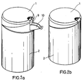
- the rotating lid 1 has one engaging in the interior of the container 2 Shell surface 6, in which they in the radial direction penetrating opening 9 is provided.
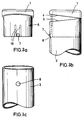
- Embodiment of the twist lock is the provided previously described embodiment radial opening 9 in the rotating lid 1 with a dispensing spout 10 provided by a hinge joint 18 on the outer surface 6 of the rotating lid 1 is articulated.
- the twist lock is the dispensing spout 10 by hand or swung outward by the action of gravity, so that about them the contents in the container 2 can be deliberately released to the outside.
- 3a to 3c is a further embodiment of the twist lock shown to the versatile Applicability of such a screw cap also for to show other purposes.
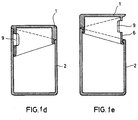
- this embodiment serves the rotating cover 1 for closing a tube or a hollow cylindrical rod, e.g. For Towel holder or the like can be used.
- On the in the Interior of the body 2 engaging outer surface 6 of the Rotary cover 1 is a locking projection 7 with the help of grooves 19 arranged resiliently.
- This locking tab 7 can in a in the inner surface of the Engage body 2 provided locking recess 8, as shown in particular in Fig. 3b.
- Locking projection 7 and locking recess 8 can not only be arranged in the manner shown here be in which the rotating lid 1 in the "Open position" of the body 2 is locked. As before previously explained, diverge in this "open position” the mutually facing axial sides 4 and 5 of the rotating cover 1 and the body 2.
- locking projection 7 and locking recess 8 in a manner not shown here also be arranged so that they lock together, when the rotating cover 1 is in its "closed position" located in which the mutually facing axial Pages 4 and 5 are aligned.
- rotating lid 1 and the body 2 as separate Parts made for each. Preferably be these parts are injection molded from plastic or in another Manufactured way.
- Rotary lid 1 and body 2 can therefore have different colors to match the aesthetic To further optimize the impression of the screw cap.
- the rotating lid 1 can be different on its outside Shaping and patterning around the aesthetic impression of the required requirements and adapt applications. It can also Rotating lid 1 against another rotating lid 1 at one otherwise the same screw cap can be replaced.
Abstract
Description
Die Erfindung bezieht sich auf einen Drehverschluß der im Oberbegriff des
Patentanspruchs 1 genannten Art.The invention relates to a rotary closure in the preamble of
Bei einem solchen, aus dem DE-U-19 60 248 bekannten Drehverschluß ist in den Hals eines Behälters ein den Körper bildender Pfropfen mit Hilfe einer einstückigen Federung eingesetzt. Der Pfropfen besteht aus einem koaxialen Mittelpfosten, der an seinem axialen Ende einen mit einer axialen Durchgangsbohrung des Drehdeckels zusammenwirkenden Ventilkörper trägt. Mit Hilfe der Federung kann der koaxiale Mittelpfosten und damit auch der Ventilkörper bei geschlossenem Drehdeckel axial nach innen gedrückt werden, wodurch die Durchgangsbohrung in dem Drehdeckel freigegeben wird, um den Behälter von außen füllen zu können. Zur Abgabe des im Behälter enthaltenen Füllgutes wird der Drehdeckel teilweise aufgedreht, wodurch sich die Durchgangsbohrung des Drehdeckels von dem Ventilkörper in axialer Richtung entfernt, um einen freien Auslaßquerschnitt freizugeben. Die den Pfropfen bzw. den Mittelpfosten haltende Federung umfaßt radiale Rippen, die an der Innenmantelfläche des Körpers festgelegt sind und mit dem koaxialen Mittelpfosten verbunden sind.In such a, known from DE-U-19 60 248 twist lock is in the Neck of a container a plug forming the body with the help of a one-piece Suspension used. The stopper consists of a coaxial central post attached to the its axial end one with an axial through hole of the rotary cover cooperating valve body carries. With the help of the suspension, the coaxial Middle post and thus also the valve body with the rotating lid closed axially be pressed inwards, creating the through hole in the rotating lid is released so that the container can be filled from the outside. To deliver the in Containers filled contents, the rotating lid is partially unscrewed, whereby the through hole of the rotary cover of the valve body in the axial Direction away to reveal a free outlet cross section. The stopper or the suspension holding the mullion comprises radial ribs on the Inner lateral surface of the body are fixed and with the coaxial mullion are connected.
Aus der DE-A-26 24 354 ist ein Spender zum Verteilen von fließfähigem, flüssigem Klebstoff bekannt, der einen den Klebstoff aufnehmenden hohlzylindrischen Körper und eine auf dessen Oberteil aufgesetzte hohlzylindrische Hülse aufweist, die nach oben in einer eine kreiszylindrische Form aufweisenden Austragsfläche mündet. Der Körper hat an seinem Oberteil einen als Ausnehmung ausgebildeten Schraubengewindegang, der mit einem an der Innenmantelfläche der Hülse als Vorsprung ausgebildeten entsprechenden Schraubengewindegang kämmt, um ein Gewinde zu bilden, das bei einer Drehung der Hülse um ca. 180° eine axiale Verschiebung der Hülse gegenüber dem Körper bewirkt. Die einander zugewandten axialen Seiten der Hülse und des Körpers verlaufen in einer zur Achse des Körpers um einen bestimmten Winkel geneigten Ebene, wobei dieser Winkel von der Steigung der Gewindegänge abhängt. Bei gegenüber dem Körper voll abgesenkter Hülse fluchten diese axialen Seiten im wesentlichen miteinander. Auf dem oberen Teil des Körpers ist eine mit einer sich nach oben erstreckenden schmalen Kanüle versehene Kappe aufgeschraubt. Die Kanüle bildet an ihrem freien Ende eine kreiszylindrische Austragfläche kleinen Durchmessers, um flüssigen Klebstoff in kleinen Mengen bzw. auf hinsichtlich ihren Abmessungen begrenzten Flächen auftragen zu können. Soll dagegen Klebstoff großflächiger aufgetragen werden, wird die Hülse mit Hilfe des Gewindes in axialer Richtung nach oben verschoben, bis die Austragfläche der Hülse mit der Austragfläche der Kanüle fluchtet, um damit eine relativ große Austragfläche zum Auftragen von Klebstoff zu bilden. Die obere Mündung der Kanüle kann bei abgesenkter Hülse mit einer gesonderten Kappe verschlossen werden, die über ein flexibles Halteband an der Hülse befestigt ist.DE-A-26 24 354 discloses a dispenser for distributing flowable, liquid Adhesive known, the one of the hollow cylindrical body receiving the adhesive and has a hollow cylindrical sleeve placed on the upper part thereof opens into a discharge surface having a circular cylindrical shape at the top. Of the Body has a recess formed on its upper part Screw thread, which with a on the inner surface of the sleeve as Projection trained corresponding screw thread meshes to a To form a thread that is axial when the sleeve is rotated by approximately 180 ° Displacement of the sleeve relative to the body causes. The facing each other axial sides of the sleeve and the body run in one to the axis of the body plane inclined by a certain angle, this angle from the Slope of the threads depends. When fully lowered compared to the body These axial sides are essentially aligned with one another. On the top Part of the body is one with a narrow cannula extending upwards screwed cap. The cannula forms one at its free end circular cylindrical discharge surface of small diameter to liquid adhesive in small quantities or in areas with limited dimensions to be able to apply. If, on the other hand, adhesive is to be applied over a large area, the sleeve with the help of the thread in the axial direction upwards until the Discharge surface of the sleeve is aligned with the discharge surface of the cannula to create a to form a relatively large discharge area for applying adhesive. The upper The cannula can be opened with the sleeve lowered using a separate cap be closed, which is attached to the sleeve via a flexible retaining strap.
Aufgabe der Erfindung ist es, einen derartigen Drehverschluß so auszubilden, daß er in einfacher Weise herzustellen ist, leicht zu handhaben ist und eine unbehinderte Abgabe von in dem Körper enthaltenen Füllgut ermöglicht.The object of the invention is to design such a twist lock so that it is simple to manufacture, easy to use and unimpeded Dispensing of contents contained in the body enables.
Bei einem Drehverschluß der genannten Art ist diese Aufgabe durch die im
kennzeichnenden Teil des Patentanspruchs 1 angegebenen Merkmale gelöst.With a twist lock of the type mentioned, this task is performed by the
characterizing part of
Der erfindungsgemäße Drehverschluß zeichnet sich dadurch aus, daß der Drehdeckel mit Hilfe der elliptischen Führungselemente eine axiale Verschiebung zum Körper ausführt, wenn er gegenüber diesem um 180° gedreht wird. Bei dieser axialen Verschiebung wird der Drehdeckel in der geöffneten Stellung des Behälters jedoch nicht von dem Körper gelöst, sondern es wird vielmehr eine in dem Drehdeckel axial oder radial vorgesehene Öffnung freigegeben, um in dem Körper vorhandenes Füllgut nach außen abgeben zu können. Die einander zugewandten axialen Seiten-ränder sowohl des Drehdeckels als auch des Körpers verlaufen in einer gegenüber der Achse des Körpers um einen bestimmten Winkel geneigten Ebene. In der geschlossenen Stellung des Drehverschlusses fluchten diese abgeschrägten Seiten miteinander, während sie in der geöffneten Stellung des Drehver-schlusses divergieren.The rotary lock according to the invention is characterized in that the Rotary cover with the help of the elliptical guide elements an axial displacement to the body when it is rotated 180 ° relative to it. At this Axial displacement is the rotating lid in the open position of the container however, not detached from the body, but rather becomes one in that Rotary cover axially or radially provided opening to open in the body to be able to deliver existing contents to the outside. The facing each other axial side edges of both the rotating lid and the body run in one inclined at a certain angle with respect to the axis of the body Level. When the screw cap is in the closed position, they are aligned bevelled sides with each other while in the open position of the Diverter lock diverge.
Obwohl Drehdeckel und Körper des Drehverschlusses im normalen Betrieb auch in der Öffnungsstellung nicht voneinander getrennt werden, werden sie als getrennte Einzelteile vorzugsweise aus Kunststoff hergestellt, wodurch sie unterschiedliche Farben haben können, um den ästhetischen Eindruck des Drehverschlusses zu optimieren.Although the screw cap and body of the screw cap are also in normal operation the open position are not separated from each other, they are considered separate Items preferably made of plastic, which makes them different Colors can have to give the aesthetic impression of the twist lock optimize.
Ausgestaltungen der Erfindung sind in den Unteransprüchen angegeben. Embodiments of the invention are specified in the subclaims.
Ausführungsbeispiele der Erfindung werden anhand der Zeichnung erläutert.Embodiments of the invention are based on the Drawing explained.
In den Fig. 1a bis 1e ist ein Ausführungsbeispiel des
Drehverschlusses gezeigt, bei dem der Körper 2 selbst
als Behälter ausgebildet ist. Der Drehdeckel 1 weist
eine in den Innenraum des Behälters 2 eingreifende
Mantelfläche 6 auf, in der eine sie in radialer Richtung
durchdringende Öffnung 9 vorgesehen ist.1a to 1e is an embodiment of the
Twist lock shown, in which the
Bei der in Fig. 1 gezeigten geschlossenen Stellung des
Drehverschlusses wird die Öffnung 9 von der Mantelfläche
des Behälters 2 vollständig abgedeckt. Der Behälter 2
ist also geschlossen.In the closed position of the
Rotary lock is the opening 9 of the outer surface
of the
Bei der in Fig. 2 gezeigten Öffnungsstellung des
Drehverschlusses ist die Öffnung 9 von der Mantelfläche
des Behälters 2 vollständig freigegeben, so daß in dem
Behälter 2 befindliches Füllgut durch die Öffnung 9 hindurch
abgegeben werden kann.In the open position of the
Twist lock is the opening 9 from the outer surface
of the
Bei dem in den Fig. 2a bis 2e dargestellten weiteren
Ausführungsbeispiel des Drehverschlusses ist die bei dem
zuvor erläuterten Ausführungsbeispiel vorgesehene
radiale Öffnung 9 im Drehdeckel 1 mit einer Abgabetülle
10 versehen, die über ein Scharniergelenk 18 an der Mantelfläche
6 des Drehdeckels 1 gelenkig angebracht ist.
In der in Fig. 2a, 2c und 2d gezeigten Öffnungsstellung
des Drehverschlusses wird die Ausgabetülle 10 von Hand
oder durch Schwerkraftwirkung nach außen geschwenkt, so
daß über sie das in dem Behälter 2 befindliche Füllgut
gezielt nach außen abgegeben werden kann.In the further shown in FIGS. 2a to 2e
Embodiment of the twist lock is the
provided previously described embodiment
Bei einer Drehung des Drehdeckels 1 um 180° in die
Schließstellung des Drehverschlusses, die in den Fig. 2b
und 2e dargestellt ist, wird die Ausgabetülle 10
selbsttätig nach oben und damit in eine die Öffnung verschließende
Stellung geschwenkt.When turning the
Aufbau und Wirkungsweise dieses Ausführungsbeispiels entsprechen im übrigen der des in Fig. 1 gezeigten AusführungsbeispielsStructure and operation of this embodiment otherwise correspond to that of the exemplary embodiment shown in FIG. 1
In den Fig. 3a bis 3c ist ein weiteres Ausführungsbeispiel
des Drehverschlusses gezeigt, um die vielseitige
Anwendbarkeit eines solchen Drehverschlusses auch für
andere Zwecke zu zeigen. Bei diesem Ausführungsbeispiel
dient der Drehdeckel 1 zum Verschließen eines Rohres
oder einer hohlzylindrischen Stange, wie sie z.B. für
Handtuchhalter od. dgl. verwendet werden. An der in den
Innenraum des Körpers 2 eingreifenden Mantelfläche 6 des
Drehdeckels 1 ist ein Verriegelungsvorsprung 7 mit Hilfe
von Nuten 19 federnd angeordnet. Dieser Verriegelungsvorsprung
7 kann in eine in der Innenmantelfläche des
Körpers 2 vorgesehene Verriegelungsausnehmung 8 eingreifen,
wie dieses insbesondere in Fig. 3b gezeigt ist.
Verriegelungsvorsprung 7 und Verriegelungsausnehmung 8
können dabei nicht nur in der hier gezeigten Weise angeordnet
werden, bei der der Drehdeckel 1 in der
"Öffnungsstellung" des Körpers 2 verriegelt ist. Wie bereits
zuvor erläutert, divergieren in dieser "Öffnungsstellung"
die einander zugewandten axialen Seiten 4 und
5 des Drehdeckels 1 und des Körpers 2.3a to 3c is a further embodiment
of the twist lock shown to the versatile
Applicability of such a screw cap also for
to show other purposes. In this embodiment
serves the
Andererseits können Verriegelungsvorsprung 7 und Verriegelungsausnehmung
8 in hier nicht gezeigter Weise aber
auch so angeordnet werden, daß sie miteinander verrasten,
wenn sich der Drehdeckel 1 in seiner "Schließstellung"
befindet, bei der die einander zugewandten axialen
Seiten 4 und 5 miteinander fluchten.On the other hand,
Bei allen gezeigten und erläuterten Ausführungsbeispielen
werden der Drehdeckel 1 und der Körper 2 als getrennte
Teile jeweils für sich hergestellt. Vorzugsweise werden
diese Teile dabei aus Kunststoff gespritzt oder in anderer
Weise hergestellt. Drehdeckel 1 und Körper 2 können
daher unterschiedliche Farben haben, um den ästhetischen
Eindruck des Drehverschlusses weiter zu optimieren.In all the exemplary embodiments shown and explained
the
Der Drehdeckel 1 kann an seiner Außenseite unterschiedliche
Formgebungen und Bemusterungen aufweisen, um den
ästhetischen Eindruck an die jeweils gewünschten Erfordernisse
und Anwendungen anzupassen. Dabei kann auch der
Drehdeckel 1 gegen einen anderen Drehdeckel 1 bei einem
sonst gleichen Drehverschluß ausgetauscht werden.The rotating
Claims (6)
- Turning closure for closing the opening of a hollow cylindrical body (2), wherein a hollow cylindrical turning lid (1) displaceable within the body and the body (2) have guide elements mating with each other in form-locking relationship, which on rotation of the turning lid (1) cause axial displacement of the turning lid (1) relative to the body (2), characterised in that the guide elements are a guide element of elliptical circumference formed on an inwardly offset cylindrical surface region of the turning lid (1) and projecting radially outwards, and a guide element of elliptical circumference formed on a corresponding cylindrical surface of the body (2) and projecting radially inwards, which in each case extend in a plane inclined at an acute angle to the axis of the body (2), and in that the axial side edges (4, 5) of the cylindrical surfaces of the outwardly offset region of the turning lid (1) and body (2) facing towards each other extend in a plane inclined at this acute angle, so that in the closed position these side edges (4, 5) and also the outer cylindrical surfaces of the turning lid (1) and body (2) are aligned with each other.
- Turning closure according to claim 1, characterised in that on the cylindrical surface (6) of the turning lid (1) which engages in the hollow cylindrical body (2) is provided a radially outwardly extending locking projection (7) which can engage resiliently in a corresponding locking recess (8) in the inner cylindrical surface of the body (2) (Fig. 3).
- Turning closure according to claim 1, characterised in that on the cylindrical surface (6) of the turning lid (1) which engages in the hollow cylindrical body (2) is provided an opening (9) penetrating this cylindrical surface (6), in such a way that in the closed position it is completely covered by the cylindrical surface of the body (2) and in the open position obtained by axial displacement it is exposed by the cylindrical surface of the body (2), and in that the body (2) is a container holding material which can be dispensed through the opening (9) (Fig. 1).
- Turning closure according to claim 3, characterised in that the opening (9) is provided with a dispensing spout (10) which is mounted pivotably on the turning lid (1) and which on axial displacement of the turning lid (1) in the closing direction is automatically pivotable into a position aligned with the cylindrical surface (6) of the turning lid (1) and closing the opening (9) (Fig. 2).
- Turning closure according to any of claims 1 to 4, characterised in that the body (2) and the turning lid (1) are made as separate components from plastic.
- Turning closure according to any of claims 1 to 5, characterised in that the elliptical guide elements mating with each other are provided with notches in order to produce latching positions at the end points of the 180° rotation.
Applications Claiming Priority (3)
| Application Number | Priority Date | Filing Date | Title |
|---|---|---|---|
| DE8904496U | 1989-04-10 | ||
| DE8904496U DE8904496U1 (en) | 1989-04-10 | 1989-04-10 | |
| EP90106302A EP0392314B1 (en) | 1989-04-10 | 1990-04-02 | Turnable closure to close the axial opening of a hollow cylinder-body |
Related Parent Applications (2)
| Application Number | Title | Priority Date | Filing Date |
|---|---|---|---|
| EP90106302A Division EP0392314B1 (en) | 1989-04-10 | 1990-04-02 | Turnable closure to close the axial opening of a hollow cylinder-body |
| EP90106302.4 Division | 1990-04-02 |
Publications (2)
| Publication Number | Publication Date |
|---|---|
| EP0615917A1 EP0615917A1 (en) | 1994-09-21 |
| EP0615917B1 true EP0615917B1 (en) | 1998-07-29 |
Family
ID=6838139
Family Applications (2)
| Application Number | Title | Priority Date | Filing Date |
|---|---|---|---|
| EP94107235A Expired - Lifetime EP0615917B1 (en) | 1989-04-10 | 1990-04-02 | Turnable closure to close the axial opening of a hollow cylinder-body |
| EP90106302A Expired - Lifetime EP0392314B1 (en) | 1989-04-10 | 1990-04-02 | Turnable closure to close the axial opening of a hollow cylinder-body |
Family Applications After (1)
| Application Number | Title | Priority Date | Filing Date |
|---|---|---|---|
| EP90106302A Expired - Lifetime EP0392314B1 (en) | 1989-04-10 | 1990-04-02 | Turnable closure to close the axial opening of a hollow cylinder-body |
Country Status (5)
| Country | Link |
|---|---|
| US (1) | US5135139A (en) |
| EP (2) | EP0615917B1 (en) |
| AT (2) | ATE114591T1 (en) |
| DE (3) | DE8904496U1 (en) |
| DK (2) | DK0392314T3 (en) |
Families Citing this family (9)
| Publication number | Priority date | Publication date | Assignee | Title |
|---|---|---|---|---|
| CH680360A5 (en) * | 1991-09-17 | 1992-08-14 | Supermatic Kunststoff Ag | |
| US5743444A (en) * | 1996-12-06 | 1998-04-28 | Creative Packaging Corp. | Twist dispensing closure |
| US6223957B1 (en) | 2000-02-17 | 2001-05-01 | Richard G. Hoppe | Plug for insertion into and removably sealing an annulus in a nozzle connected to a container of extrudable material and method of use |
| US6422433B2 (en) * | 2000-06-02 | 2002-07-23 | Sussex Technologies, Inc. | Dispensing cap with flexible sealing post |
| US6675995B2 (en) * | 2000-06-05 | 2004-01-13 | Stull Technologies, Inc. | Traversing twist cap |
| US6299038B1 (en) | 2000-09-06 | 2001-10-09 | Courtesy Corporation | Telescoping twist closure |
| CN102482009B (en) * | 2009-07-16 | 2014-08-20 | 西奎斯特闭合罗夫勒有限公司 | Dispensing closure |
| US8881947B2 (en) * | 2010-06-23 | 2014-11-11 | Müslüm Yildirim | Dispensing container |
| DE202010015802U1 (en) * | 2010-11-25 | 2011-02-10 | Hidde, Axel R., Dr. Ing. | Bottle cap with reset function |
Family Cites Families (17)
| Publication number | Priority date | Publication date | Assignee | Title |
|---|---|---|---|---|
| US1917833A (en) * | 1931-12-15 | 1933-07-11 | Henry B Finley | Collapsible tube structure |
| US1997863A (en) * | 1933-03-28 | 1935-04-16 | Hansen James | Valve |
| US2129687A (en) * | 1937-01-19 | 1938-09-13 | Gustav Drews | Collapsible tube closure and method for making the same |
| FR1132199A (en) * | 1955-10-08 | 1957-03-06 | Salines De Dombasle Sa Des | Spout and container on which it is mounted |
| DE1736919U (en) * | 1956-10-17 | 1956-12-27 | Eisenwerk Streuber & Lohmann G | SCREW CONNECTION FOR CONTAINER, BARREL OR. DGL. WITH EXTENDABLE SPOUT PIPE. |
| US3342385A (en) * | 1965-12-20 | 1967-09-19 | Johnson & Johnson | Container with closure and dispensing cap |
| US3357605A (en) * | 1966-05-09 | 1967-12-12 | Formold Plastics Inc | Dispensing closure |
| US3370764A (en) * | 1966-12-29 | 1968-02-27 | Stull Engraving Co | Dispensing screw-type closure cap |
| DE1586601A1 (en) * | 1967-01-03 | 1970-06-25 | Martin Espinal | Registering pill dispenser |
| DE1946268C3 (en) * | 1969-09-12 | 1980-01-03 | Friedrich Sanner Kg, 6140 Bensheim | Safety box for medication |
| FR2157690B3 (en) * | 1971-10-25 | 1974-06-07 | Maestracci Charles | |
| DE2353742C2 (en) * | 1973-10-26 | 1983-08-04 | Robert Finke Kunststoff-Spritzguss-Werk, 5950 Finnentrop | Cap closure for bottles and the like with child protection device |
| DE2624354A1 (en) * | 1976-05-31 | 1977-12-15 | Lingner & Fischer Gmbh | Free flowing glue dispensing device - has cap engaging with spiral groove in compressible vessel |
| DE2644947A1 (en) * | 1976-10-05 | 1978-04-06 | Creative Closure Ass | Closure unit for compressible container - has sleeve movable so end opening fits lightly or tightly fits on closure stem |
| US4234093A (en) * | 1979-05-21 | 1980-11-18 | Tyson Raymond K | Pill dispenser with safety features |
| DE3147903A1 (en) * | 1981-12-03 | 1983-06-16 | Ferber, Rolf, Dr., 8057 Zürich | PLASTIC HINGE ARM ARRANGEMENT |
| FR2575443B1 (en) * | 1984-12-28 | 1987-10-30 | Air Sec | SAFETY CLOSURE FOR PLASTIC TUBE |
-
1989
- 1989-04-10 DE DE8904496U patent/DE8904496U1/de not_active Expired - Lifetime
-
1990
- 1990-04-02 AT AT90106302T patent/ATE114591T1/en not_active IP Right Cessation
- 1990-04-02 EP EP94107235A patent/EP0615917B1/en not_active Expired - Lifetime
- 1990-04-02 AT AT94107235T patent/ATE168956T1/en not_active IP Right Cessation
- 1990-04-02 EP EP90106302A patent/EP0392314B1/en not_active Expired - Lifetime
- 1990-04-02 DK DK90106302.4T patent/DK0392314T3/en active
- 1990-04-02 DE DE59010842T patent/DE59010842D1/en not_active Expired - Fee Related
- 1990-04-02 DK DK94107235T patent/DK0615917T3/en active
- 1990-04-02 DE DE59007793T patent/DE59007793D1/en not_active Expired - Fee Related
- 1990-04-03 US US07/504,119 patent/US5135139A/en not_active Expired - Fee Related
Also Published As
| Publication number | Publication date |
|---|---|
| EP0392314A2 (en) | 1990-10-17 |
| DK0615917T3 (en) | 1999-04-26 |
| DE59010842D1 (en) | 1998-09-03 |
| ATE114591T1 (en) | 1994-12-15 |
| EP0392314B1 (en) | 1994-11-30 |
| EP0392314A3 (en) | 1990-12-05 |
| ATE168956T1 (en) | 1998-08-15 |
| DE59007793D1 (en) | 1995-01-12 |
| DK0392314T3 (en) | 1995-03-13 |
| EP0615917A1 (en) | 1994-09-21 |
| US5135139A (en) | 1992-08-04 |
| DE8904496U1 (en) | 1990-06-21 |
Similar Documents
| Publication | Publication Date | Title |
|---|---|---|
| DE3036139C2 (en) | ||
| DE1782279A1 (en) | Liquid container with valve closure | |
| DE3626154A1 (en) | MEASURING CUP CLOSURE AND METHOD FOR MOUNTING THE CLOSURE | |
| DE1486735B1 (en) | Tap or tap | |
| DE102006060143B3 (en) | Seal for a drinking bottle has sealing top and bottom parts with a through-flow opening running into a mouth piece and a cover to pull over the sealing top part | |
| EP0142651B1 (en) | Tooth or shaving brush with a reservoir | |
| DE2646027A1 (en) | DISPENSER WITH APPLICATION BALL | |
| WO1989000958A1 (en) | Closure for containers with retractable spout | |
| EP0615917B1 (en) | Turnable closure to close the axial opening of a hollow cylinder-body | |
| DE2226556C3 (en) | Screw cap of a liquid container | |
| CH672625A5 (en) | ||
| DE3433533A1 (en) | DEVICE FOR STORING AND DELIVERING A VOLATILE SUBSTANCE OR VOLATILE COMPOUNDS | |
| EP1746041A1 (en) | A rotatable and reclosable closure | |
| EP0163109B1 (en) | Dispensing device | |
| DE3619455A1 (en) | LIQUID DISPENSER FOR REPEATING DISPENSING AMOUNTS OF A LIQUID PRODUCT | |
| EP0379692B1 (en) | Brush for applying a liquid containing a volatile solvent, in particular a nail varnish | |
| DE19652148C2 (en) | Containers, especially bottles | |
| EP0087562B1 (en) | Dispenser for fluid, viscous or powdered products | |
| DE7534301U (en) | Childproof lock for containers, especially for containers containing pourable goods | |
| DE3830641C1 (en) | Closure for a bottle for correction fluid | |
| DE102004017765B3 (en) | Sealing device for a two-component packaging comprises a connecting sleeve, an insert part, a securing device, a cylindrical casing, spokes, control ramps, a dispensing opening, threaded cams, and control cams | |
| DE60303516T2 (en) | ISSUE GUN | |
| DE8214974U1 (en) | Container for two-component products | |
| DE1453010C (en) | Closure on a container with order and distribution device for liquid contents | |
| EP0060983A1 (en) | Container with safety closure |
Legal Events
| Date | Code | Title | Description |
|---|---|---|---|
| PUAI | Public reference made under article 153(3) epc to a published international application that has entered the european phase |
Free format text: ORIGINAL CODE: 0009012 |
|
| AC | Divisional application: reference to earlier application |
Ref document number: 392314 Country of ref document: EP |
|
| AK | Designated contracting states |
Kind code of ref document: A1 Designated state(s): AT BE CH DE DK FR GB IT LI LU NL SE |
|
| 17P | Request for examination filed |
Effective date: 19950321 |
|
| 17Q | First examination report despatched |
Effective date: 19960523 |
|
| GRAG | Despatch of communication of intention to grant |
Free format text: ORIGINAL CODE: EPIDOS AGRA |
|
| GRAG | Despatch of communication of intention to grant |
Free format text: ORIGINAL CODE: EPIDOS AGRA |
|
| GRAH | Despatch of communication of intention to grant a patent |
Free format text: ORIGINAL CODE: EPIDOS IGRA |
|
| GRAH | Despatch of communication of intention to grant a patent |
Free format text: ORIGINAL CODE: EPIDOS IGRA |
|
| GRAA | (expected) grant |
Free format text: ORIGINAL CODE: 0009210 |
|
| AC | Divisional application: reference to earlier application |
Ref document number: 392314 Country of ref document: EP |
|
| AK | Designated contracting states |
Kind code of ref document: B1 Designated state(s): AT BE CH DE DK FR GB IT LI LU NL SE |
|
| REF | Corresponds to: |
Ref document number: 168956 Country of ref document: AT Date of ref document: 19980815 Kind code of ref document: T |
|
| REG | Reference to a national code |
Ref country code: CH Ref legal event code: NV Representative=s name: BOVARD AG PATENTANWAELTE Ref country code: CH Ref legal event code: EP |
|
| GBT | Gb: translation of ep patent filed (gb section 77(6)(a)/1977) |
Effective date: 19980729 |
|
| REF | Corresponds to: |
Ref document number: 59010842 Country of ref document: DE Date of ref document: 19980903 |
|
| ET | Fr: translation filed | ||
| PG25 | Lapsed in a contracting state [announced via postgrant information from national office to epo] |
Ref country code: LU Free format text: LAPSE BECAUSE OF NON-PAYMENT OF DUE FEES Effective date: 19990402 Ref country code: GB Free format text: LAPSE BECAUSE OF NON-PAYMENT OF DUE FEES Effective date: 19990402 Ref country code: AT Free format text: LAPSE BECAUSE OF NON-PAYMENT OF DUE FEES Effective date: 19990402 |
|
| PG25 | Lapsed in a contracting state [announced via postgrant information from national office to epo] |
Ref country code: SE Free format text: LAPSE BECAUSE OF NON-PAYMENT OF DUE FEES Effective date: 19990403 |
|
| REG | Reference to a national code |
Ref country code: DK Ref legal event code: T3 |
|
| PG25 | Lapsed in a contracting state [announced via postgrant information from national office to epo] |
Ref country code: LI Free format text: LAPSE BECAUSE OF NON-PAYMENT OF DUE FEES Effective date: 19990430 Ref country code: DK Free format text: LAPSE BECAUSE OF NON-PAYMENT OF DUE FEES Effective date: 19990430 Ref country code: CH Free format text: LAPSE BECAUSE OF NON-PAYMENT OF DUE FEES Effective date: 19990430 Ref country code: BE Free format text: LAPSE BECAUSE OF NON-PAYMENT OF DUE FEES Effective date: 19990430 |
|
| PLBE | No opposition filed within time limit |
Free format text: ORIGINAL CODE: 0009261 |
|
| STAA | Information on the status of an ep patent application or granted ep patent |
Free format text: STATUS: NO OPPOSITION FILED WITHIN TIME LIMIT |
|
| 26N | No opposition filed | ||
| BERE | Be: lapsed |
Owner name: CREANOVA A.G. Effective date: 19990430 |
|
| PG25 | Lapsed in a contracting state [announced via postgrant information from national office to epo] |
Ref country code: NL Free format text: LAPSE BECAUSE OF NON-PAYMENT OF DUE FEES Effective date: 19991101 |
|
| GBPC | Gb: european patent ceased through non-payment of renewal fee |
Effective date: 19990402 |
|
| REG | Reference to a national code |
Ref country code: CH Ref legal event code: PL |
|
| PG25 | Lapsed in a contracting state [announced via postgrant information from national office to epo] |
Ref country code: FR Free format text: LAPSE BECAUSE OF NON-PAYMENT OF DUE FEES Effective date: 19991231 |
|
| NLV4 | Nl: lapsed or anulled due to non-payment of the annual fee |
Effective date: 19991101 |
|
| EUG | Se: european patent has lapsed |
Ref document number: 94107235.7 |
|
| REG | Reference to a national code |
Ref country code: FR Ref legal event code: ST |
|
| PG25 | Lapsed in a contracting state [announced via postgrant information from national office to epo] |
Ref country code: DE Free format text: LAPSE BECAUSE OF NON-PAYMENT OF DUE FEES Effective date: 20000201 |
|
| REG | Reference to a national code |
Ref country code: DK Ref legal event code: EBP |
|
| PG25 | Lapsed in a contracting state [announced via postgrant information from national office to epo] |
Ref country code: IT Free format text: LAPSE BECAUSE OF NON-PAYMENT OF DUE FEES Effective date: 20050402 |