EP0615893B1 - One-piece knuckle assembly - Google Patents
One-piece knuckle assembly Download PDFInfo
- Publication number
- EP0615893B1 EP0615893B1 EP93104402A EP93104402A EP0615893B1 EP 0615893 B1 EP0615893 B1 EP 0615893B1 EP 93104402 A EP93104402 A EP 93104402A EP 93104402 A EP93104402 A EP 93104402A EP 0615893 B1 EP0615893 B1 EP 0615893B1
- Authority
- EP
- European Patent Office
- Prior art keywords
- flanged body
- steering
- tie rod
- steering knuckle
- arm
- Prior art date
- Legal status (The legal status is an assumption and is not a legal conclusion. Google has not performed a legal analysis and makes no representation as to the accuracy of the status listed.)
- Expired - Lifetime
Links
Images


Classifications
-
- B—PERFORMING OPERATIONS; TRANSPORTING
- B21—MECHANICAL METAL-WORKING WITHOUT ESSENTIALLY REMOVING MATERIAL; PUNCHING METAL
- B21K—MAKING FORGED OR PRESSED METAL PRODUCTS, e.g. HORSE-SHOES, RIVETS, BOLTS OR WHEELS
- B21K1/00—Making machine elements
- B21K1/74—Making machine elements forked members or members with two or more limbs, e.g. U-bolts, anchors
-
- B—PERFORMING OPERATIONS; TRANSPORTING
- B60—VEHICLES IN GENERAL
- B60G—VEHICLE SUSPENSION ARRANGEMENTS
- B60G7/00—Pivoted suspension arms; Accessories thereof
- B60G7/001—Suspension arms, e.g. constructional features
-
- B—PERFORMING OPERATIONS; TRANSPORTING
- B60—VEHICLES IN GENERAL
- B60G—VEHICLE SUSPENSION ARRANGEMENTS
- B60G9/00—Resilient suspensions of a rigid axle or axle housing for two or more wheels
-
- B—PERFORMING OPERATIONS; TRANSPORTING
- B62—LAND VEHICLES FOR TRAVELLING OTHERWISE THAN ON RAILS
- B62D—MOTOR VEHICLES; TRAILERS
- B62D7/00—Steering linkage; Stub axles or their mountings
- B62D7/18—Steering knuckles; King pins
Definitions
- This invention relates to a steering knuckle assembly for vehicles. More particularly, it relates to a one-piece steering knuckle assembly for heavy commercial vehicles such as trucks wherein the tie rod arm as well as a brake flange with or without a steering arm are forged together.
- the English language abstract of JP-A-60-138049 dicloses a one-piece steering knuckle assembly for trucks.
- the known knuckle is provided with a main body carrying the wheel spindle at one side and bosses at the opposite side of the main body.
- the bosses are provided to receive a king pin within appropriate bores.
- a steering arm and a tie rod arm are extending from bosses which tie rod arm is straight.
- the root of the tie rod arm is located at a position of the circumference of the boss which is shifted from a position opposite to the main body towards the main body itself.
- the known one-piece knuckle has a reentrant contour which only allows for casting of the knuckle.
- the invention provides a one-piece steering knuckle assembly for heavy commercial vehicles such as trucks or the like wherein a flanged body is constructed and arranged to receive a brake assembly.
- a wheel spindle extends from the flanged body.
- a tie rod arm is connected to the flanged body in a one-piece manner.
- bosses extending from the flanged body opposite the wheel spindle, the bosses having a bore which are axially aligned to receive a king pin.
- the flanged body, wheel spindle, tie rod arm and enlarged bosses are all formed from a single steel billet as a one-piece heavy duty forging.
- the forging is capable of being used in commercial vehicles having a gross vehicle weight of at least 6350 kg (14,000 lbs).
- both a tie rod arm and a steering arm are connected to the flanged body in the previously described one-piece manner.
- the flanged body is forged in the form of a brake spider.
- the steering arm or the tie rod arm are connected to the flanged body through enlarged bosses surrounding the bores for the king pin.
- the wheel spindle is connected to said flanged body in a one-piece manner and opposite the steering or tie rod arms.
- the flanged body is substantially flat and has openings therethrough for connection with the brake assembly.
- It is still another object of the invention is to provide a steering knuckle of the foregoing type wherein a brake flange is constructed with a one-piece knuckle with a steering rod arm or a tie rod arm.
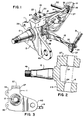
- Fig. 1 is a top perspective view illustrating the single component and unitary knuckle assembly of this invention connected to an axle.
- Fig. 2 is a view in partial vertical section of the single component knuckle assembly of Fig. 1 unconnected to the axle.
- Fig. 3 is an end view of the steering knuckle shown in Fig. 1.
- Figs. 4-11 are perspective views illustrating the forging of the steering knuckle of this invention beginning with a heated steel billet.
- Figs. 12-14 are views similar to Fig. 1 depicting additional embodiments but unconnected to an axle or any steering or tie rods.
- a flanged body 11 from which extends the usual wheel spindle 12.
- the flanged body 11 in this instance provides a brake spider 13.
- a steering arm 14 and a tie rod arm 16 At the opposing side there is integrally formed with the flanged body 11 a steering arm 14 and a tie rod arm 16.
- the usual truck axle is shown at 18 and terminates in a collar 19.
- the steering knuckle 10 is connected to the axle 18 by the king pin 21 extending through the enlarged bosses 27 and 28 of the steering arm 14 and the tie rod arm 16, respectively.
- the king pin 21 is retained in the axle 18 by the bolt and washer shown at 25.
- FIG. 2 there are the openings 24 extending through the enlarged bosses 27 and 28 to accommodate the king pin 21.
- Caps such as shown at 22 in Fig. 1 are fastened to the bosses 27 and 28 by the screws 23 to close the king pin therein.
- a steering rod 30 is pivotally connected to the steering arm 14 by the nut 36 and the bolt 37 extending through the enlarged boss 33.
- the tie rod 31 is pivotally connected to the tie rod arm 16 with the bolt and nut 37 and 36 extending through the enlarged boss 34.
- the flanged body 11 has the openings such as 39 and 40 for an attachment to the brake disk.
- FIG. 12-14 Additional embodiments generally 110, 210 and 310 are depicted in Figs. 12-14. Similar numbers are employed to designate similar parts except they are in the "100", “200” and “300” series. In comparing these embodiments with that of Fig. 1, it is seen that the connection with the axle 18 is not shown. Neither are the connections with the steering or the tie rod arms.
- embodiment 110 it is similar to embodiment 10 except that it does not have a steering arm such as 14 for connection to a steering rod.
- This embodiment 110 would be employed in a truck in a paired manner with embodiment 10 wherein embodiment 10 would be the right hand version and embodiment 110 the left hand version.
- Embodiment 110 also shows that the enlarged bosses 127 and 128 can have a rounded portion for reception of a king pin 21.
- Embodiments 210 and 310 could also be paired together on the same truck, with embodiment 210 being the left hand version and embodiment 310 the right hand version.
- Embodiments 210 and 310 differ from embodiments 10 and 110 in that the flanged bodies 211 and 311 are of the standard or conventional type which could receive a brake spider unit for connection to a brake drum assembly.
- Figs. 4-11 illustrate the forging of the steering knuckle 10 of this invention.
- the first step is that depicted in Fig. 4 where a steel billet is heated to forging conditions.
- the next step in the process is shown in Fig. 5 wherein the heated billet 42 is contacted with a forging roll to provide a reduced section such as shown at 43.
- a tail end and preform such as shown at 46 is provided and would be effected by forming the billet 42 on a die.
- a blocking step is effected in which the steering arm 14 and the tie rod arm 16 are formed as well as the flanged body 11 and the wheel spindle 12. Subsequently, and as shown in Fig.
- a finished forging impression is accomplished wherein the wheel spindle is formed in its finished form and the enlarged bosses 27 and 28 are provided on the steering arm 14 and the tie rod arm 16.
- Fig. 9 shows the next step which is flash removal such as indicated at 47 in Fig. 7 and 8.
- the tie rod arm 16 would be bent by die forming to the angular position as shown.
- the last step is shown in Fig. 11, which is a machining step in which the threads 49 are formed on the wheel spindle 12, the openings 24 and 52 are provided in the enlarged bosses 27, 28 and 33 and 34 and threaded screw bores such as 26.
- Embodiments 110, 210 and 310 would be forged in a similar manner as previously described for embodiment 10 except that in the instance of embodiments 110 and 210 the forging of the rod arm such as 14 would be eliminated.
- an important feature of this invention is the fact that the one-piece steering knuckles 10, 110, 210 or 310 by having the tie rod arms 16, 116, 216 and 316 integrally formed with the flanged body 11 eliminates the costly machining and connecting of the separate tie rod arms to prior steering knuckles. This is also true when the steering arms 14 and 314 are also integrally forged. The prior procedure requires the forming of separate bosses and machining so that threaded portions of these tie rod arms or steering arms could be fastened thereto. Further, the fact that there is a single flanged body 11 for connection to a brake drum assembly also avoids the previously used connection through the intermediate brake spider.
- the one piece steering knuckle assembly as described herein is particularly employed in conjunction with heavy duty commercial vehicles including Class 5, 6, 7 and 8 trucks and busses. It's advantages can also be realized in commercial vehicles having a gross vehicle weight of at least 6350 kg (14,000 lbs).
Landscapes
- Engineering & Computer Science (AREA)
- Mechanical Engineering (AREA)
- Chemical & Material Sciences (AREA)
- Combustion & Propulsion (AREA)
- Transportation (AREA)
- Steering-Linkage Mechanisms And Four-Wheel Steering (AREA)
- Clamps And Clips (AREA)
- Coupling Device And Connection With Printed Circuit (AREA)
- Flanged Joints, Insulating Joints, And Other Joints (AREA)
- Braking Arrangements (AREA)
Abstract
Description
- This invention relates to a steering knuckle assembly for vehicles. More particularly, it relates to a one-piece steering knuckle assembly for heavy commercial vehicles such as trucks wherein the tie rod arm as well as a brake flange with or without a steering arm are forged together.
- The English language abstract of JP-A-60-138049 dicloses a one-piece steering knuckle assembly for trucks. The known knuckle is provided with a main body carrying the wheel spindle at one side and bosses at the opposite side of the main body. The bosses are provided to receive a king pin within appropriate bores. A steering arm and a tie rod arm are extending from bosses which tie rod arm is straight. The root of the tie rod arm is located at a position of the circumference of the boss which is shifted from a position opposite to the main body towards the main body itself. As a consequence the known one-piece knuckle has a reentrant contour which only allows for casting of the knuckle.
- In the prior art it is known to provide a steering knuckle for bearing lubrication with tie rods which are fastened to the knuckle. This is provided in U.S. Patent 1,755,627. It is also known in the prior art to provide an integral spindle arm with a steering knuckle for suspension purposes as well as to provide an integral brake flange for attachment to a brake backing plate. This is described in U.S. Patent 2,556,767.
- There is commonly available a steering knuckle for heavy duty motor vehicles such as trucks wherein the steering arm and the tie rod arm are fitted to a steering knuckle by means of a threaded portion and a fastening nut. These heavy duty steering knuckles also employ a flanged body to which is separately attached a brake spider unit for connection to a brake drum assembly.
- There is a need in the heavy duty motor vehicle field to provide a steering knuckle assembly wherein the tie rod arm is integrally formed as a one-piece unit with the steering knuckle with or without a steering arm. This is accomplished by the present invention.
- The invention provides a one-piece steering knuckle assembly for heavy commercial vehicles such as trucks or the like wherein a flanged body is constructed and arranged to receive a brake assembly. A wheel spindle extends from the flanged body. A tie rod arm is connected to the flanged body in a one-piece manner. There are enlarged bosses extending from the flanged body opposite the wheel spindle, the bosses having a bore which are axially aligned to receive a king pin. The flanged body, wheel spindle, tie rod arm and enlarged bosses are all formed from a single steel billet as a one-piece heavy duty forging. The forging is capable of being used in commercial vehicles having a gross vehicle weight of at least 6350 kg (14,000 lbs).
- In one aspect of the invention both a tie rod arm and a steering arm are connected to the flanged body in the previously described one-piece manner.
- In a preferred manner, the flanged body is forged in the form of a brake spider.
- Also in a preferred manner, the steering arm or the tie rod arm are connected to the flanged body through enlarged bosses surrounding the bores for the king pin.
- In another aspect of the invention, the wheel spindle is connected to said flanged body in a one-piece manner and opposite the steering or tie rod arms.
- In yet another embodiment the flanged body is substantially flat and has openings therethrough for connection with the brake assembly.
- It is an object of the invention to provide an improved steering knuckle for heavy commercial vehicles.
- It is another object of the invention to provide a one-piece steering knuckle wherein the tie rod arm is integrally forged therein.
- It is yet another object of the invention to provide a steering knuckle for heavy commercial vehicles which can be manufactured at reduced cost.
- It is still another object of the invention is to provide a steering knuckle of the foregoing type wherein a brake flange is constructed with a one-piece knuckle with a steering rod arm or a tie rod arm.
- These and other objects and advantages of the invention will be apparent from the following detailed description and drawings.
- Fig. 1 is a top perspective view illustrating the single component and unitary knuckle assembly of this invention connected to an axle.
- Fig. 2 is a view in partial vertical section of the single component knuckle assembly of Fig. 1 unconnected to the axle.
- Fig. 3 is an end view of the steering knuckle shown in Fig. 1.
- Figs. 4-11 are perspective views illustrating the forging of the steering knuckle of this invention beginning with a heated steel billet.
- Figs. 12-14 are views similar to Fig. 1 depicting additional embodiments but unconnected to an axle or any steering or tie rods.
- Proceeding to a detailed description of the steering knuckle generally 10 and with reference to Figs. 1-3, there is shown a
flanged body 11 from which extends theusual wheel spindle 12. Theflanged body 11 in this instance provides abrake spider 13. At the opposing side there is integrally formed with the flanged body 11 asteering arm 14 and atie rod arm 16. The usual truck axle is shown at 18 and terminates in acollar 19. Thesteering knuckle 10 is connected to theaxle 18 by the king pin 21 extending through the enlargedbosses steering arm 14 and thetie rod arm 16, respectively. The king pin 21 is retained in theaxle 18 by the bolt and washer shown at 25. - As best seen in Fig. 2, there are the
openings 24 extending through the enlargedbosses bosses screws 23 to close the king pin therein. Asteering rod 30 is pivotally connected to thesteering arm 14 by thenut 36 and thebolt 37 extending through the enlargedboss 33. Similarly, thetie rod 31 is pivotally connected to thetie rod arm 16 with the bolt andnut boss 34. - As best seen in Figs. 1 and 3, the
flanged body 11 has the openings such as 39 and 40 for an attachment to the brake disk. - Additional embodiments generally 110, 210 and 310 are depicted in Figs. 12-14. Similar numbers are employed to designate similar parts except they are in the "100", "200" and "300" series. In comparing these embodiments with that of Fig. 1, it is seen that the connection with the
axle 18 is not shown. Neither are the connections with the steering or the tie rod arms. - Referring first to
embodiment 110, it is similar toembodiment 10 except that it does not have a steering arm such as 14 for connection to a steering rod. Thisembodiment 110 would be employed in a truck in a paired manner withembodiment 10 whereinembodiment 10 would be the right hand version andembodiment 110 the left hand version.Embodiment 110 also shows that the enlargedbosses -
Embodiments embodiment 210 being the left hand version andembodiment 310 the right hand version.Embodiments embodiments flanged bodies - Figs. 4-11 illustrate the forging of the
steering knuckle 10 of this invention. The first step is that depicted in Fig. 4 where a steel billet is heated to forging conditions. The next step in the process is shown in Fig. 5 wherein the heatedbillet 42 is contacted with a forging roll to provide a reduced section such as shown at 43. Next, and as shown in Fig. 6, a tail end and preform such as shown at 46 is provided and would be effected by forming thebillet 42 on a die. After this, and as shown in Fig. 7, a blocking step is effected in which thesteering arm 14 and thetie rod arm 16 are formed as well as theflanged body 11 and thewheel spindle 12. Subsequently, and as shown in Fig. 8, a finished forging impression is accomplished wherein the wheel spindle is formed in its finished form and theenlarged bosses steering arm 14 and thetie rod arm 16. Fig. 9 shows the next step which is flash removal such as indicated at 47 in Fig. 7 and 8. In Fig. 10, thetie rod arm 16 would be bent by die forming to the angular position as shown. The last step is shown in Fig. 11, which is a machining step in which thethreads 49 are formed on thewheel spindle 12, theopenings enlarged bosses -
Embodiments embodiment 10 except that in the instance ofembodiments - An important feature of this invention is the fact that the one-
piece steering knuckles tie rod arms flanged body 11 eliminates the costly machining and connecting of the separate tie rod arms to prior steering knuckles. This is also true when the steeringarms flanged body 11 for connection to a brake drum assembly also avoids the previously used connection through the intermediate brake spider. All of these features are incorporated in a one piece steering knuckle assembly which is forged from a single billet of steel for use in heavy duty commercial vehicles such as trucks. This unitary construction not only provides for a rugged and reliable connection, but also reduces the costs of additional components as well as machining and the enlarged connecting bosses which require additional steel for their fabrication. - The one piece steering knuckle assembly as described herein is particularly employed in conjunction with heavy duty commercial vehicles including Class 5, 6, 7 and 8 trucks and busses. It's advantages can also be realized in commercial vehicles having a gross vehicle weight of at least 6350 kg (14,000 lbs).
- Steel is the preferred metal used in forging the billet into a unitary steering knuckle. While the steering arms such as 14 and the tie rod arms such as 16 are shown at certain geometric positions with respect to the
flanged body 11, it is obvious that they can take various forms and angles with respect thereto. - The foregoing invention can now be practiced by those skilled in the art.
Claims (7)
- A one-piece steering knuckle assembly (10,110, 210,310) for heavy commercial vehicles having a gross vehicle weight of at least 6350 kg (14,000 lbs.) comprising:a flanged body (11,111,211,311) constructed and arranged to receive a brake assembly, said flanged body (11,111,211,311) having first and second generally planar sides;a wheel spindle (12,112,212,312) extending from said flanged body (11,111,211,311) on its first side;upper and lower enlarged bosses (27,28,127,128,227, 228,327,328) extending from said flanged body (11,111,211, 311) on its second side opposite said wheel spindle (12,112,212, 312), said bosses (27,28,127,128,227,228,327,328) having a bore (24,124,224,324) with said bores (24,124,224,324) being axially aligned to receive a king pin (21); anda tie rod arm (16,116,216,316) extending from said lower enlarged boss (28,128,228,328) and away from said second side of said flanged body (11,111,211,311) and spaces therefrom in a generally parallel manner;said flanged body (11,111,211,311), wheel spindle (12,112,212,312), tie rod arm (16,116,216,316) and enlarged bosses (27,28,127,128,227,228,327,328) all being formed from a single steel billet as a one-piece heavy duty forging.
- The steering knuckle as defined in claim 1 wherein said flanged body (11,111,211,311) is defined by a brake spider.
- The steering knuckle as defined in claim 1 wherein said flanged body (11,111,211,311) is adapted to receive a brake spider.
- The steering knuckle as defined in claim 1 further including a steering arm (14,114,214,314) extending from said upper enlarged boss (27,127,227,327) and away from said second side of said flanged body.
- The steering knuckle as defined in claim 4 wherein said steering arm (14,114,214,314) and said tie rod arm (16,116,216,316) include additional enlarged bosses (33, 34,134,234,333,334) at ends at said second side of said flanged body (11,111,211,311), said additional enlarged bosses (33,34, 134,234,333,334) having bores ((52,53) therethrough for connection with steering (30) and tie rod (31) linkages.
- The steering knuckle as defined in claim 1 wherein said wheel spindle (12,112,212,312) is connected to said flanged body (11,111,211,311) opposite said steering (14,114,214,314) and tie rod (16,116,216,316) arms.
- The steering knuckle as defined in claim 1, wherein said flanged body (11,111,211,311), is substantially flat and has openings (39,40) therethrough for connection with said brake assembly.
Priority Applications (10)
| Application Number | Priority Date | Filing Date | Title |
|---|---|---|---|
| US07/781,537 US5219176A (en) | 1989-11-02 | 1991-10-22 | One-piece steering knuckle assembly |
| ZA931879A ZA931879B (en) | 1991-10-22 | 1993-03-16 | One-piece steering knuckle assembly |
| EP93104402A EP0615893B2 (en) | 1991-10-22 | 1993-03-18 | One-piece knuckle assembly |
| AT93104402T ATE145599T1 (en) | 1991-10-22 | 1993-03-18 | ONE-PIECE JOINT DEVICE |
| DE69306240T DE69306240T3 (en) | 1991-10-22 | 1993-03-18 | One-piece joint device |
| ES93104402T ES2094948T5 (en) | 1991-10-22 | 1993-03-18 | MONOPIEZA ADDRESS ROTULA GROUP. |
| CA002092021A CA2092021C (en) | 1991-10-22 | 1993-03-19 | One-piece knuckle assembly |
| AU35493/93A AU657890B2 (en) | 1991-10-22 | 1993-03-25 | One-piece steering knuckle assembly |
| CZ93536A CZ283918B6 (en) | 1991-10-22 | 1993-03-30 | Complete steering pivot of a wheel, performed as one piece |
| BR9300910A BR9300910A (en) | 1991-06-21 | 1993-04-01 | One-piece steering axle assembly |
Applications Claiming Priority (7)
| Application Number | Priority Date | Filing Date | Title |
|---|---|---|---|
| US07/781,537 US5219176A (en) | 1989-11-02 | 1991-10-22 | One-piece steering knuckle assembly |
| ZA931879A ZA931879B (en) | 1991-10-22 | 1993-03-16 | One-piece steering knuckle assembly |
| EP93104402A EP0615893B2 (en) | 1991-10-22 | 1993-03-18 | One-piece knuckle assembly |
| CA002092021A CA2092021C (en) | 1991-10-22 | 1993-03-19 | One-piece knuckle assembly |
| AU35493/93A AU657890B2 (en) | 1991-10-22 | 1993-03-25 | One-piece steering knuckle assembly |
| CZ93536A CZ283918B6 (en) | 1991-10-22 | 1993-03-30 | Complete steering pivot of a wheel, performed as one piece |
| BR9300910A BR9300910A (en) | 1991-06-21 | 1993-04-01 | One-piece steering axle assembly |
Publications (3)
| Publication Number | Publication Date |
|---|---|
| EP0615893A1 EP0615893A1 (en) | 1994-09-21 |
| EP0615893B1 true EP0615893B1 (en) | 1996-11-27 |
| EP0615893B2 EP0615893B2 (en) | 2002-03-27 |
Family
ID=27560557
Family Applications (1)
| Application Number | Title | Priority Date | Filing Date |
|---|---|---|---|
| EP93104402A Expired - Lifetime EP0615893B2 (en) | 1989-11-02 | 1993-03-18 | One-piece knuckle assembly |
Country Status (9)
| Country | Link |
|---|---|
| US (1) | US5219176A (en) |
| EP (1) | EP0615893B2 (en) |
| AT (1) | ATE145599T1 (en) |
| AU (1) | AU657890B2 (en) |
| CA (1) | CA2092021C (en) |
| CZ (1) | CZ283918B6 (en) |
| DE (1) | DE69306240T3 (en) |
| ES (1) | ES2094948T5 (en) |
| ZA (1) | ZA931879B (en) |
Families Citing this family (32)
| Publication number | Priority date | Publication date | Assignee | Title |
|---|---|---|---|---|
| US5366233A (en) * | 1992-05-18 | 1994-11-22 | The Budd Company | Wire form steering arm link |
| JP3578500B2 (en) * | 1994-12-08 | 2004-10-20 | ティーアールダブリュ オートモーティブ ジャパン株式会社 | Spindle and manufacturing method thereof |
| AR001266A1 (en) * | 1995-03-21 | 1997-09-24 | Eaton Corp | Steering and brake ball joint for heavy or medium traffic trucks |
| US5785332A (en) * | 1996-08-01 | 1998-07-28 | Dana Corporation | Motor vehicle steering knuckle assembly |
| US6419250B1 (en) * | 1998-05-28 | 2002-07-16 | Dana Corporation | One-piece forged steering knuckle assembly |
| DE19923694B4 (en) * | 1999-05-22 | 2010-04-08 | Volkswagen Ag | pivot bearing |
| US6148968A (en) * | 1999-06-01 | 2000-11-21 | Dana Corporation | Integrated axle spindle and brake spider |
| US6398240B1 (en) * | 1999-10-29 | 2002-06-04 | Belltech, Inc. | Vehicle-lowering steering knuckle for “live” wheel hub |
| US6471224B1 (en) | 1999-12-21 | 2002-10-29 | Dana Corporation | Kingpin independent front suspension |
| US6499752B1 (en) | 2000-08-07 | 2002-12-31 | Dana Corporation | Steer axle assembly |
| US6367825B1 (en) * | 2000-10-30 | 2002-04-09 | Meritor Heavy Vehicle Technology, Llc | Adjustable kingpin boss |
| FR2816886B1 (en) * | 2000-11-21 | 2003-03-14 | Valmex | PROCESS FOR THE MANUFACTURE OF A PLATFORM ROCKET, AND PLATFORM ROCKET WHICH CAN BE OBTAINED BY IMPLEMENTING THIS PROCESS |
| US6659482B2 (en) * | 2002-01-03 | 2003-12-09 | Meritor Light Vehicle Technology, Llc | Composite spring and control arm |
| US7401677B2 (en) * | 2002-02-13 | 2008-07-22 | Trw Inc. | Self-centering steering system |
| FR2837775B1 (en) | 2002-03-27 | 2004-07-09 | Valmex | TRAY ROCKET, TRAY FOR SAME AND MANUFACTURING METHOD |
| US20040124696A1 (en) * | 2002-11-20 | 2004-07-01 | Brunner Drilling And Manufacturing Inc. | Dust cup and wheel spindle |
| US7093843B2 (en) * | 2003-05-14 | 2006-08-22 | Arvinmeritor Technology Llc | King pin arrangement for steering knuckle |
| DE10321878B4 (en) * | 2003-05-15 | 2005-04-28 | Daimler Chrysler Ag | Independent wheel suspension with elastic wheel carrier bearing |
| KR100545295B1 (en) * | 2003-09-29 | 2006-01-24 | 현대모비스 주식회사 | Steering knuckle assembly for a steering apparatus in a motor vehicle |
| US20080034830A1 (en) * | 2006-08-14 | 2008-02-14 | Tidwell Charles S | Systems and Methods for Reducing Metal Fatigue in Forged Parts |
| DE102008031709B4 (en) | 2008-07-04 | 2012-03-29 | Man Truck & Bus Ag | Disc brake assembly for a vehicle, in particular for a commercial vehicle |
| US20100038873A1 (en) * | 2008-08-14 | 2010-02-18 | Stoyan Stoychey | Steering knuckle with spindle and method of making same |
| US8857833B2 (en) | 2011-11-15 | 2014-10-14 | Dana Heavy Vehicle Systems Group, Llc | Vehicle knuckle with bolt-on steer arm |
| US9096259B2 (en) * | 2012-07-30 | 2015-08-04 | Arvinmeritor Technology, Llc | Steering knuckle assembly with snap ring spindle retention and a method of manufacture |
| US9291223B2 (en) * | 2013-05-21 | 2016-03-22 | Arvinmeritor Technology, Llc | Axle assembly having a steering knuckle |
| MX2016012217A (en) * | 2014-03-25 | 2016-12-16 | Hendrickson Usa Llc | Fabricated steering knuckles. |
| CN104210548B (en) * | 2014-08-29 | 2016-05-11 | 万向钱潮股份有限公司 | A kind of knuckle connector assembly that is applicable to rectilinear translation formula front suspension |
| US20180105909A1 (en) * | 2015-04-02 | 2018-04-19 | Honda Motor Co., Ltd. | Forging method |
| CN105057557A (en) * | 2015-08-03 | 2015-11-18 | 重庆海獒精密锻造有限公司 | Forging molding technological method for multi-lug part |
| WO2018029713A2 (en) | 2016-08-12 | 2018-02-15 | Bharat Forge Limited | Steering knuckle and its manufacturing |
| CA171198S (en) * | 2016-10-24 | 2017-05-23 | Mevotech Lp | Outer tie rod end |
| CN111572630A (en) * | 2020-06-18 | 2020-08-25 | 山西中晋工业机械有限公司 | Knuckle for engineering truck |
Family Cites Families (22)
| Publication number | Priority date | Publication date | Assignee | Title |
|---|---|---|---|---|
| CH75020A (en) * | 1916-10-24 | 1917-05-16 | Oscar Ramuz | Flexible element intended for the construction of walls, ceilings, vaults, etc., process for its manufacture and machine for the implementation of this process |
| US1755627A (en) * | 1927-07-02 | 1930-04-22 | Auto Research Corp | Lubrication of bearings on pivoted structures |
| US2556767A (en) * | 1946-10-23 | 1951-06-12 | Ford Motor Co | Independent wheel suspension |
| FR1057043A (en) * | 1952-03-12 | 1954-03-04 | Daimler Benz Ag | Steering knuckle for vehicle steering wheels |
| DE1061632B (en) * | 1958-03-14 | 1959-07-16 | Porsche Kg | Independent suspension, especially for motor vehicles |
| US3542392A (en) * | 1968-10-14 | 1970-11-24 | Rockwell Standard Co | Steering mechanism |
| US3908480A (en) * | 1970-10-13 | 1975-09-30 | Dayton Walther Corp | Interlocking knuckle assembly |
| US3749415A (en) * | 1971-06-21 | 1973-07-31 | Gen Motors Corp | Steering knuckle assembly |
| US3865394A (en) * | 1973-06-11 | 1975-02-11 | Gen Motors Corp | Sheet metal steering knuckle with integral steering arm |
| US3889512A (en) * | 1974-03-13 | 1975-06-17 | Ralph D Delio | Steering knuckles and method of forming the same |
| US4452347A (en) * | 1981-04-30 | 1984-06-05 | Rockwell International Corporation | Brake spider |
| JPS60138046A (en) * | 1983-12-27 | 1985-07-22 | Hitachi Metals Ltd | Steering knuckle for truck |
| JPS60138045A (en) * | 1983-12-27 | 1985-07-22 | Hitachi Metals Ltd | Steering knuckle for truck |
| JPS60138047A (en) * | 1983-12-27 | 1985-07-22 | Hitachi Metals Ltd | Steering knuckle for truck |
| JPS60138049A (en) * | 1983-12-27 | 1985-07-22 | Hitachi Metals Ltd | Steering knuckle for truck |
| US4690418A (en) * | 1985-05-07 | 1987-09-01 | V. W. Kaiser Engineering, Inc. | Steering knuckle and kingpin assembly |
| US4693487A (en) * | 1985-11-01 | 1987-09-15 | Cooper Randy G | Steering knuckle and spindle assembly |
| US4736964A (en) * | 1986-12-29 | 1988-04-12 | Specktor Gerald A | Locking cam for adjustment of automobile wheel alignment |
| JPS63251310A (en) * | 1987-04-08 | 1988-10-18 | Honda Motor Co Ltd | Four-wheel-steering vehicle |
| US4761019A (en) * | 1987-09-04 | 1988-08-02 | Chrysler Motors Corporation | Steering knuckle assembly |
| DE3736666A1 (en) * | 1987-10-29 | 1989-05-18 | Opel Adam Ag | Steering axle for a motor vehicle |
| US4967584A (en) * | 1988-02-19 | 1990-11-06 | Nissan Motor Co., Ltd. | Method of making a forging in closed-dies |
-
1991
- 1991-10-22 US US07/781,537 patent/US5219176A/en not_active Expired - Lifetime
-
1993
- 1993-03-16 ZA ZA931879A patent/ZA931879B/en unknown
- 1993-03-18 EP EP93104402A patent/EP0615893B2/en not_active Expired - Lifetime
- 1993-03-18 AT AT93104402T patent/ATE145599T1/en not_active IP Right Cessation
- 1993-03-18 ES ES93104402T patent/ES2094948T5/en not_active Expired - Lifetime
- 1993-03-18 DE DE69306240T patent/DE69306240T3/en not_active Expired - Fee Related
- 1993-03-19 CA CA002092021A patent/CA2092021C/en not_active Expired - Fee Related
- 1993-03-25 AU AU35493/93A patent/AU657890B2/en not_active Ceased
- 1993-03-30 CZ CZ93536A patent/CZ283918B6/en not_active IP Right Cessation
Also Published As
| Publication number | Publication date |
|---|---|
| US5219176A (en) | 1993-06-15 |
| AU3549393A (en) | 1994-10-06 |
| CA2092021A1 (en) | 1994-09-20 |
| AU657890B2 (en) | 1995-03-23 |
| ATE145599T1 (en) | 1996-12-15 |
| ZA931879B (en) | 1993-10-25 |
| DE69306240D1 (en) | 1997-01-09 |
| EP0615893B2 (en) | 2002-03-27 |
| EP0615893A1 (en) | 1994-09-21 |
| DE69306240T3 (en) | 2003-07-10 |
| CZ53693A3 (en) | 1994-10-19 |
| ES2094948T5 (en) | 2002-11-16 |
| CZ283918B6 (en) | 1998-07-15 |
| DE69306240T2 (en) | 1997-06-12 |
| CA2092021C (en) | 2000-07-18 |
| ES2094948T3 (en) | 1997-02-01 |
Similar Documents
| Publication | Publication Date | Title |
|---|---|---|
| EP0615893B1 (en) | One-piece knuckle assembly | |
| US6419250B1 (en) | One-piece forged steering knuckle assembly | |
| JP2523436B2 (en) | Automotive steering knuckle assembly | |
| US6616156B1 (en) | Steering knuckle | |
| US5516130A (en) | Forged control arm | |
| EP1043212B1 (en) | Steering knuckle and suspension module | |
| JPH0296358U (en) | ||
| US20110241304A1 (en) | Mounting arrangement for lower steering arm | |
| US20060108763A1 (en) | Suspension control arm assembly for vehicles | |
| EP0227276B1 (en) | Nonrotatable clamp for automotive steering linkage | |
| JPH08169205A (en) | Integral axle tube and yoke assembly for front wheel drive axle assembly and vehicle axle assembly | |
| AU2002307439B2 (en) | Dual draw key arrangement for clamping steer axle kingpin | |
| US6719311B2 (en) | Vehicle steering assembly | |
| EP1800996A1 (en) | Heavy duty steer axle with live spindles | |
| AU2002307439A1 (en) | Dual draw key arrangement for clamping steer axle kingpin | |
| US6508481B2 (en) | Outer tie rod assembly connector body | |
| JP3245803B2 (en) | Integrated steering knuckle assembly | |
| RU2087361C1 (en) | Steering knuckle unit for heavy commercial vehicles | |
| US3967857A (en) | Spindle for a vehicle wheel, provided with at least one ball joint | |
| KR100234935B1 (en) | One-piece steering knuckle assembly | |
| MXPA99004915A (en) | Assembly of steering pivot, forged of a pi | |
| HU216249B (en) | Single-cast steering knuckle fitting | |
| US2370098A (en) | Motor vehicle | |
| SK280666B6 (en) | One-piece knuckle assembly | |
| JPH0723286Y2 (en) | Car suspension |
Legal Events
| Date | Code | Title | Description |
|---|---|---|---|
| PUAI | Public reference made under article 153(3) epc to a published international application that has entered the european phase |
Free format text: ORIGINAL CODE: 0009012 |
|
| AK | Designated contracting states |
Kind code of ref document: A1 Designated state(s): AT DE ES FR GB IT SE |
|
| 17P | Request for examination filed |
Effective date: 19941007 |
|
| 17Q | First examination report despatched |
Effective date: 19950725 |
|
| GRAG | Despatch of communication of intention to grant |
Free format text: ORIGINAL CODE: EPIDOS AGRA |
|
| GRAH | Despatch of communication of intention to grant a patent |
Free format text: ORIGINAL CODE: EPIDOS IGRA |
|
| GRAH | Despatch of communication of intention to grant a patent |
Free format text: ORIGINAL CODE: EPIDOS IGRA |
|
| GRAA | (expected) grant |
Free format text: ORIGINAL CODE: 0009210 |
|
| AK | Designated contracting states |
Kind code of ref document: B1 Designated state(s): AT DE ES FR GB IT SE |
|
| REF | Corresponds to: |
Ref document number: 145599 Country of ref document: AT Date of ref document: 19961215 Kind code of ref document: T |
|
| REF | Corresponds to: |
Ref document number: 69306240 Country of ref document: DE Date of ref document: 19970109 |
|
| REG | Reference to a national code |
Ref country code: ES Ref legal event code: FG2A Ref document number: 2094948 Country of ref document: ES Kind code of ref document: T3 |
|
| ITF | It: translation for a ep patent filed |
Owner name: ING. C. GREGORJ S.P.A. |
|
| ET | Fr: translation filed | ||
| PLBQ | Unpublished change to opponent data |
Free format text: ORIGINAL CODE: EPIDOS OPPO |
|
| PLBI | Opposition filed |
Free format text: ORIGINAL CODE: 0009260 |
|
| PLBF | Reply of patent proprietor to notice(s) of opposition |
Free format text: ORIGINAL CODE: EPIDOS OBSO |
|
| 26 | Opposition filed |
Opponent name: CARL DAN PEDDINGHAUS GMBH & CO. KG Effective date: 19970827 |
|
| PLBF | Reply of patent proprietor to notice(s) of opposition |
Free format text: ORIGINAL CODE: EPIDOS OBSO |
|
| PLBF | Reply of patent proprietor to notice(s) of opposition |
Free format text: ORIGINAL CODE: EPIDOS OBSO |
|
| PLBF | Reply of patent proprietor to notice(s) of opposition |
Free format text: ORIGINAL CODE: EPIDOS OBSO |
|
| RDAH | Patent revoked |
Free format text: ORIGINAL CODE: EPIDOS REVO |
|
| APAC | Appeal dossier modified |
Free format text: ORIGINAL CODE: EPIDOS NOAPO |
|
| APAE | Appeal reference modified |
Free format text: ORIGINAL CODE: EPIDOS REFNO |
|
| APAC | Appeal dossier modified |
Free format text: ORIGINAL CODE: EPIDOS NOAPO |
|
| APAC | Appeal dossier modified |
Free format text: ORIGINAL CODE: EPIDOS NOAPO |
|
| PLAW | Interlocutory decision in opposition |
Free format text: ORIGINAL CODE: EPIDOS IDOP |
|
| REG | Reference to a national code |
Ref country code: GB Ref legal event code: IF02 |
|
| PUAH | Patent maintained in amended form |
Free format text: ORIGINAL CODE: 0009272 |
|
| STAA | Information on the status of an ep patent application or granted ep patent |
Free format text: STATUS: PATENT MAINTAINED AS AMENDED |
|
| 27A | Patent maintained in amended form |
Effective date: 20020327 |
|
| AK | Designated contracting states |
Kind code of ref document: B2 Designated state(s): AT DE ES FR GB IT SE |
|
| ET3 | Fr: translation filed ** decision concerning opposition | ||
| REG | Reference to a national code |
Ref country code: ES Ref legal event code: DC2A Kind code of ref document: T5 Effective date: 20020627 |
|
| APAH | Appeal reference modified |
Free format text: ORIGINAL CODE: EPIDOSCREFNO |
|
| PGFP | Annual fee paid to national office [announced via postgrant information from national office to epo] |
Ref country code: AT Payment date: 20060303 Year of fee payment: 14 |
|
| PGFP | Annual fee paid to national office [announced via postgrant information from national office to epo] |
Ref country code: FR Payment date: 20060317 Year of fee payment: 14 |
|
| PGFP | Annual fee paid to national office [announced via postgrant information from national office to epo] |
Ref country code: ES Payment date: 20060327 Year of fee payment: 14 |
|
| PGFP | Annual fee paid to national office [announced via postgrant information from national office to epo] |
Ref country code: DE Payment date: 20070430 Year of fee payment: 15 |
|
| PG25 | Lapsed in a contracting state [announced via postgrant information from national office to epo] |
Ref country code: AT Free format text: LAPSE BECAUSE OF NON-PAYMENT OF DUE FEES Effective date: 20070318 |
|
| PGFP | Annual fee paid to national office [announced via postgrant information from national office to epo] |
Ref country code: IT Payment date: 20070528 Year of fee payment: 15 |
|
| REG | Reference to a national code |
Ref country code: FR Ref legal event code: ST Effective date: 20071130 |
|
| REG | Reference to a national code |
Ref country code: ES Ref legal event code: FD2A Effective date: 20070319 |
|
| PG25 | Lapsed in a contracting state [announced via postgrant information from national office to epo] |
Ref country code: FR Free format text: LAPSE BECAUSE OF NON-PAYMENT OF DUE FEES Effective date: 20070402 Ref country code: ES Free format text: LAPSE BECAUSE OF NON-PAYMENT OF DUE FEES Effective date: 20070319 |
|
| PG25 | Lapsed in a contracting state [announced via postgrant information from national office to epo] |
Ref country code: DE Free format text: LAPSE BECAUSE OF NON-PAYMENT OF DUE FEES Effective date: 20081001 |
|
| PG25 | Lapsed in a contracting state [announced via postgrant information from national office to epo] |
Ref country code: IT Free format text: LAPSE BECAUSE OF NON-PAYMENT OF DUE FEES Effective date: 20080318 |
|
| PGFP | Annual fee paid to national office [announced via postgrant information from national office to epo] |
Ref country code: SE Payment date: 20110329 Year of fee payment: 19 |
|
| PGFP | Annual fee paid to national office [announced via postgrant information from national office to epo] |
Ref country code: GB Payment date: 20110325 Year of fee payment: 19 |
|
| REG | Reference to a national code |
Ref country code: SE Ref legal event code: EUG |
|
| PG25 | Lapsed in a contracting state [announced via postgrant information from national office to epo] |
Ref country code: SE Free format text: LAPSE BECAUSE OF NON-PAYMENT OF DUE FEES Effective date: 20120319 |
|
| GBPC | Gb: european patent ceased through non-payment of renewal fee |
Effective date: 20120318 |
|
| PG25 | Lapsed in a contracting state [announced via postgrant information from national office to epo] |
Ref country code: GB Free format text: LAPSE BECAUSE OF NON-PAYMENT OF DUE FEES Effective date: 20120318 |